1
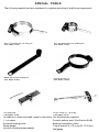
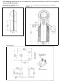
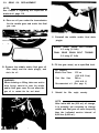
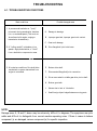
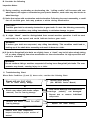
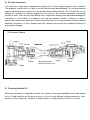
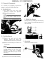
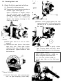
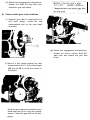
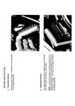
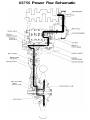
XS750 Power Flow Schematic
THE BASIC MECHANISM
1-1. An Introduction to the Mechanism
Power i s transmitted from the crankshaft
through the clutch and two transmission shafts
to a third shaft, called the middle driven gear.
A splined drive cam fits inside the middle
driven gear and transmits power t o the driven
cam, which is located on the middle gear
shaft. The drive and driven cams act as a
shock damper in the drive line. These cams
remain i n the same position relative to each
other; that is, they do not "ratchet" or slip
over when under heavy load. The middle gear
case contains two geared shafts; the drive
pinion (shaft and gear) and the driven pinion
(gear). A flange rides on the driven pinion
spline and is bolted t o the ball joint. The ball
joint acts like the universal joints i n an automobile drive shaft. The ball joint is permanentl y lubricated and rarely requires replacement.
The swing arm (rear arm) serves as both a
suspension component and a housing for the
drive shaft. Power is transmitted through the
ball joint t o the drive shaft, and t o the splined
gear coupling in the final gear case. In the
Final Gear Case, the power is transmitted t o
the Drive Pinion, through the Ring Gear, and
finally to the rear wheel.
NOTE:
The following illustrations represent only
selected components and not the actual
complete assembly.
Ball j o i n t
I
&'
The main service concerns of the Middle
Gear Case assembly are:
(1) Gear Lash: The play between the gear
teeth. This can be adjusted by shimming.
(2) Tooth Patterns: The locations and patterns of contact that are made on the gear
teeth. This can be adjusted by shimming.
(3) Bearing Clearance: The distance between
a bearing and i t s bearing housing cap.
This is an extremely small clearance that
must be carefully adjusted by shimming.
Gear
(4) Bearing Preload: The set load forcing
tapered roller bearings against their races.
In this case it is measured as the torsional
resistance of the driven pinion bearings. I t
is usually adjusted by replacing the
Expansion Spacer and very carefully
adjusting the torque on the special nut.
1-2. Lubrication
The maintenance of proper lubrication i s the most important consideration that can be given t o
the shaft drive system by the owner or service person. Almost any significant wear or failure can
usually be traced t o low lubricant level, contaminated lubricant, or the wrong choice of gear oil.
See Chapter 3 for specific gear oil recommendations and checking procedures.
1-3. Identification
Some component assemblies, such as the Middle Gear Case assembly, may contain components of
more than one type. These different types will be identified in the text as Type 1 or Type 2.
Precise serial number identification of applicable machines is not available.
Type
Identifying Feature
Middle Gear Case
Housing cap
Final Gear Case
The application of parts of the individual types will be discussed in the appropriate section of this
manual.
NOTE:
Type 1 Final Gear ............... See Type 1 preload specification (spacer type)
Type 2 Final Gear ............... See Type 2 preload specification (expansion spacer type)
SPECIAL TOOLS
The following special tools are necessary for complete servicing of shaft drive components.
Gear l a s h measurement tool (final gear)
Gear lash measurement tool (middle gear)
P.No.90890-01231
P.No.90890-01230
Middle and final gear holding tool
Ring gear holding tool
P.No.90890-01229
P.No. 90890-01254
Dial gauge stand
Torque wrench (0 - 30 cm-kg)
P.No.90890-01232
P.No.90890-05147
In addition t o these tools and common hand tools, the following are required:
1 - t o n press
Universal bearing puller
Feeler gauges
Loctite or similar thread sealant
Contact pattern paint (See Section 6-2)
Bearing installation collars
ft-lbs)
Torque wrench 0 -~10 m-kg (0 ~ 70 ft-lb)
Dial gauge
The following special tools are not available but can be constructed for shaft drive component
disassembly and assembly:
Press Tool No. 1 For final gear guide
coller removal (see page126)
Final Gear Stand
Press Tool No. 2 For final gear roller bearing and oil seal installation
(see page 130)
ROUTINE MAINTENANCE AND INSPECTION
3-1. GEAR OIL TYPE AND QUANTITY
Middle Gear Oil Capacity: 375 cc
(13.0 U.S. fluid oz)
Final Gear Oil Capacity: 300 cc
(10.0 U.S. fluid oz)
*
WE90
- sAEa0
0°C 5’C 10~c15°c
If desired, an SAE 8OW/90 hypoid gear oil
may be used for all conditions.
NOTE:
“GL-4” is a gear oil quality and additive
rating. “GL-5” or “GL-6” designated gear
oils of the proper weight may also be used.
3-2. OIL LEVEL MEASUREMENT
A. Place the machine on a level surface and
place it on the center stand. The engine
should be cool (at atmospheric temperature). Allow 2 minutes for oil to drain to
bottom of cases.
B. Remove the oil filler cap. Check the oil
level with level gauge (from tool kit) as
shown. The correct oil level is between
the two marks on each end of the level
gauge. Use end of gauge marked “REAR”
for measuring the rear (final) gear case.
Use the end marked “MIDDLE” for
measuring the middle gear case.
NOTE:
Middle gear and final gear oil can be
checked with same level gauge, which is
in the owners tool kit.
3-3. GEAR OIL REPLACEMENT
NOTE:
See Chapter 4 regarding the inspection of
drained oil. page 110
A. Place an oil pan under the transmission
for the middle gear and under the final
gear case.
C. Reinstall the middle and/or final drain
plug(s).
MIDDLE GEAR DRAIN BOLTTORQUE:
4.3 m-kg (31 ft-lb)
FINAL GEAR DRAIN BOLT TORQUE:
2.3 m-kg (17 ft-lb)
B. Remove the middle and/or final gear oil
filler cap(s) and the drain plug(s), and
drain the oil.
WARNING:
When draining or filling, take care not to
allow foreign material to enter the middle
and/or final gear case. Do not allow the
gear oil to contact the tire and wheel.
D. Fill the gear case(s) up to specified level.
Oil Capacity:
Middle Gear Case:
375 cc
(13.0 U.S. fl. oz)
Final Gear Case:
300 cc
(10.0 U.S. fl. oz)
Recommended oil: (See page 9)
E.
Reinstall
the
filler
cap(s)
securely.
NOTE:
After initial 400 km (250 mi) oil change,
it is normally not necessary to change
middle and final gear oil more frequently
than the indicated service interval of
9,600 km (6,000 mi ).
TROUBLESHOOTING
4-1. TROUBLESHOOTING CONDITIONS
Basic conditions
1. A pronounced hesitation or "jerky"
movement during acceleration, decelera
tion, or sustained speed. (This must not
be confused with engine surging or
transmission characteries).
2. A "rolling rumble" noticeabte a t low
Possible damaged areas
A. Damage t o bearings.
B.
Improper gear lash; improper gear tooth contact.
C.
Gear tooth damage.
D. Drive flange/ball joint bolts loose.
speed; a high-pitched whine; a "clunk"
from a shaft drive component or area.
3. A locked-up condition of the shaft drive
mechanism; no power transmitted from
engine t o rear wheel.
E.
Broken drive shaft.
F.
Disconnected flange/ball joint connection.
G.
Driven cam seized t o middle gear drive pinion shaft.
H. Broken gear teeth.
I.
Seizure due t o lack of lubrication.
J.
Small foreign object lodged between moving parts.
NOTE:
Damage areas A, B and C above may be extremely difficult t o diagnose. The symptoms are quite
subtle and difficult t o distinguish from normal machine operating noise. I f there is reason t o believe
component ( s ) are damaged, remove component (s) for specific inspection.
B. Consider the following
Inspection Notes:
(1) During coasting, accelerating or decelerating, the “rolling rumble” will increase with rear
wheel speed, not engine or transmission gear speeds. However, such noise may also be due to
wheel bearings.
(2) Noise that varies with acceleration and deceleration: Following incorrect reassembly, a condition of too-little gear lash may produce a whine during deceleration.
CAUTION:
Too-little gear lash is extremely destructive to gear teeth. If a test ride following reassembly
indicates this condition, stop riding immediately to minimize damage to gears.
(3) A slight “thunk” must be distinguished from normal machine operation. It will be most
noticeable at low speed and could indicate broken gear teeth.
WARNING:
If broken gear teeth are suspected, stop riding immediately. This condition could lead to
locking-up of the shaft drive assembly and result in harm to a rider.
(4) If the drive flange/ball joint bolts are slightly loose, a “clunk” may be felt when slowly taking
off, or when changing from slow acceleration to slow deceleration. At high speed this will
result in vibration.
WARNING:
Do not continue riding a machine suspected of having loose flange/ball joint bolts. The components may break, causing injury to a rider.
C. Troubleshooting Chart
Where Basic Conditions (1) and (2) above exist, consider the following Chart:
Feel for wheel bearing damage.
Replace wheel bearing.
(See XS750D Service Manual)
No
r
Check rear wheel (with brake caliper
removed). Feel for bearing damage.
Yes
Remove rear wheel
bearing damage.
Rear wheel bearings and shaft drive
No
not damaged.
9 bearings probably
Repeat test or remove individual
components.
Replace rear wheel bearing.
No
Remove drive shaft components.
Inspect according to proper section of
manual.
D. Oil Leak Inspection
If a shaft drive component is suspected of leaking oil, first thoroughly clean the entire machine.
The apparent location of an oil leak on a dusty machine may be misleading. Dry the machine and
apply a leak-localizing compound or a dry-powder spray deodorant that will limit the flow of any
leaking oil. Operate the machine prepared in this way for the distance necessary to percisely
locate the leak. There are the possibilities that a component housing may have been damaged by
road debris or an accident, or a gasket or seal may be cracked or broken. However, on new or
nearly new machines an apparent oil leak may be the result of a rust-preventive coating or excess
assembly lubrication of seals. Always clean the machine and recheck the suspected location of
any apparent leakage.
Oil Seals and Gaskets
Rubber seal
(Drive shaft housing in
swing arm contains no oil)
O-ring
E. Checking Drained Oil
Whenever a problem is suspected in either the middle or final gear assemblies, drain and inspect
the oil. Metal particles on the drain plug or in the oil could indicate a bearing seizure or other
problem i n the component. However, a small amount of metal particles in the oil is normal.
REMOVAL OF COMPONENTS
5-1. Removal of Components
It is normally not necessary to remove the
engine t o remove the Middle Gear Case.
A. Drive Shaft Joint
(1) Pull rubber boot from drive shaft
coupling t o expose four (4) bolts.
(2)Remove 4 coupling bolts;
NOTE:
Use the rear brake t o lock the drive
shaft.
C. Middle Gear Removal
Remove seven (7) middle gear case securing
bolts, Remove the meddle gear case, drive
cam and spring.
B. Final Gear Removal
( 1 ) Remove rear axle and left shock
absorber. Remove rear wheel. See
XS750D Service Manual for procedures.
(2) Remove 4 nuts holding Final Drive unit
t o swing arm.
NOTE:
Keep the Final Drive pinion bearing
housing attached t o the Final Drive
assembly. I t may tend to separate
from the Final Gear (for Type 1 Final
Gear only).
(3) Remove the Final Drive Gear assembly.
1. Drive cam
2 . Sprlng
D. Drive Shaft
Remove drive shaft as shown.
5-2. Checking Gear Lash
A. Check final drive gear lash as follows
(1) Remove final drive gear case.
(2) Temporarily secure bearing housing as
follows (Type 1 and Type 2):
Place a thickness of washer (about
1/4 inch thick) over 2 opposite
bearing housing studs. Install 2 nuts
on these studs and temporarily
tighten the bearing housing to the
final drive housing.
1 . Gear lash measurement tool
(6)Mount a dial gauge against the lash
measurement tool a t the scribed mark
(60 mm (2.36 in) from the center of
the shaft).
1. Washers
(3) Place gear case in a vice or other
support.
(4) Remove one nut from a final drive
case stud bolt. Place gear holder
(Special Tool) over ring gear surface
and stud bolt. Tighten holder to stud
bolt with nut.
(7) Use special wrench to gently rotate
gear coupling back and forth. Note
the lash measurement on the dial gauge.
FINAL GEAR LASH
0.25 - 0.50 mm (0.010 - 0.020 in):
When using the measurment tool.
0.1 - 0.2 mm (0.004-0.008 in):
Actual gear lash on the final gear
teeth.
I.
( 5 ) Install final gear lash measurement
tool on gear coupling (input side).
1 . Middle and final gear holding tool
(8) Check this engagement a t 4 positions.
Rotate the shaft 90° each time and
repeat the gear lash check.
0.1
- 0.2 mm (0.004 - 0.008 in):
Measured value and actual gear lash
B. Check middle gear lash as follows
( 1 ) Support gear case in a vise by the out.
put shaft flange. Install the lash
measurement tool on the input shaft
as shown.
1. Middle and final gear holding tool
1. Gear lash measurement tool
(2) Mount a dial gauge against the lash
measurement tool a t the scribed mark
(34 mm (1.34 in) from the center of
the shaft).
(3) Hold the gear case and rotate the input
shaft back and forth using the special
wrench. Read the gear lash on the dial
gauge.
( 4 ) Check this engagement at 4 positions.
Rotate the driven pinion shaft 90°
each time and repeat the gear lash
check.