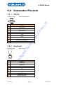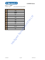
1
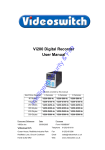
Ltd
an
dF
ire
Vi-R2000 Series Net Recorder
User Manual
Products covered by this manual
cu
rity
Vi-R2005
Int
ell
ige
nt
Se
Vi-R2001
Document Reference
Date
Firmware
Mdr601a1.doc
14/12/2012
120823
Videoswitch
Telephone
01252-851510
Ocean House, Redfields Industrial Park
Fax
01252-851296
Redfields Lane, Church Crookham
Email
[email protected]
Hants GU52 0RD
Web
www.videoswitch.co.uk
Videoswitch
Mdr601a.doc
Videoswitch
Mdr601a.doc
nt
ige
ell
Int
cu
rity
Se
ire
an
dF
Ltd
Vi-R2000 Series
Contents
1 Getting Started ......................................1
1.1.
Monitors ..............................................................................................................................2
1.2.
Control ................................................................................................................................3
1.1.1
Vi-R2001 Keyboard Control.............................................................................................4
1.1.2
Vi-R2005 Keyboard Control.............................................................................................5
1.1.3
Mouse Control .................................................................................................................6
1.1.4
Mouse Emulator Control..................................................................................................6
1.1.5
External Keyboards .........................................................................................................7
Ltd
2 Installation .............................................8
1.3.
Preventive and Cautionary Tips...........................................................................................9
1.4.
Connecting Up ..................................................................................................................11
1.5.
ire
3 Commissioning ...................................13
Password Access ..............................................................................................................14
1.6.
Default Passwords ........................................................................................................14
an
dF
3.1.1
Record Settings.................................................................................................................15
Schedule .......................................................................................................................15
3.1.3
Resolution .....................................................................................................................15
3.1.4
Quality...........................................................................................................................15
3.1.5
Frame Rate ...................................................................................................................15
3.1.6
Copy settings to all other Cameras................................................................................15
3.1.7
Retention Period Tables ................................................................................................15
cu
rity
3.1.2
4 User ......................................................18
1.7.
Live Viewing ......................................................................................................................19
4.1.1
Full screen.....................................................................................................................19
4.1.2
Multi-Screen ..................................................................................................................19
1.8.
Auto-Sequencing...........................................................................................................19
Se
4.1.3
Playback and Video Export................................................................................................20
1.9.
nt
5 Reference .............................................21
Menu .................................................................................................................................22
Manual Record ..............................................................................................................22
5.1.2
Video Search.................................................................................................................22
5.1.3
Event Search.................................................................................................................22
5.1.4
Manual Alarm ................................................................................................................22
5.1.5
HDD ..............................................................................................................................22
5.1.6
Settings .........................................................................................................................22
5.1.7
Maintenance..................................................................................................................23
5.1.9
5.2
ell
Int
5.1.8
ige
5.1.1
Help...............................................................................................................................23
Shutdown ......................................................................................................................23
Connector Pin-outs............................................................................................................25
5.2.1
Alarms...........................................................................................................................25
5.2.2
Keyboard.......................................................................................................................25
5.2.3
1.10.
VGA ..............................................................................................................................26
Technical Specifications ....................................................................................................28
5.2.4
Video.............................................................................................................................28
5.2.5
Audio.............................................................................................................................28
5.2.6
Recording......................................................................................................................28
5.2.7
Playback .......................................................................................................................28
5.2.8
Storage .........................................................................................................................28
5.2.9
Network .........................................................................................................................28
5.2.10
Interface ........................................................................................................................29
Videoswitch
Mdr601a.doc
Vi-R2000 Series
Power............................................................................................................................29
5.2.12
Environmental ...............................................................................................................29
5.2.13
Dimensions & Weight ....................................................................................................29
Int
ell
ige
nt
Se
cu
rity
an
dF
ire
Ltd
5.2.11
Videoswitch
Mdr601a.doc
Vi-R2000 Series
Int
ell
ige
nt
Se
cu
rity
an
dF
ire
Ltd
1 Getting Started
Videoswitch
Page 1
Mdr601a.doc
Vi-R2000 Series
1.1.
Monitors
VGA Monitor
A VGA monitor is recommended in order to benefit from high resolution images. Supported resolutions
are: 1024x768 and 1280x1024. The VGA monitor should be plugged in before applying power to the
DVR so that is detected. If no monitor is attached, the BNC output becomes the main monitor.
BNC Monitor
The BNC monitor is the AUX monitor if a VGA monitor is used and can display full screen and split
screen formats that are independent to the VGA monitor.
Ltd
The BNC is the MAIN monitor if no VGA monitor is present.
Int
ell
ige
nt
Se
cu
rity
an
dF
ire
The external keyboard port supports Vi-K1 and Vi-K2 series keyboards and allows remote control of
the DVR. The DVR sends video over CAT5 to a BNC connector on the keyboard for connection to a
monitor. This displays the same image as the BNC output on the DVR.
Videoswitch
Page 2
Mdr601a.doc
Vi-R2000 Series
1.2.
Control
The R-series DVRs have various methods of control. A single method or a mixture of methods can be
employed according to personal preference:
• Control by keys in standard mode - arrow keys step from field to field in the menus.
Control by external mouse – a mouse moves pointer smoothly around the screen. The left
button selects items on the screen and right button brings up a menu when in live mode.
•
Control by mouse emulator – the Up/Down/Left/Right keys perform the functions of a mouse,
moving the pointer smoothly around the screen. SEL is the left button. Press the 0 button and
hold for 1 second to simulate a right button click. The ESC key takes you back a menu level.
Int
ell
ige
nt
Se
cu
rity
an
dF
ire
Ltd
•
Videoswitch
Page 3
Mdr601a.doc
Vi-R2000 Series
Vi-R2001 Keyboard Control
Key
Function(s)
1, 2, 3, 4, 5, 6,
7, 8, 9, 0
Live: 1 – 8 Select full screen cameras
Ltd
1.1.1
ire
Mouse Emulator Mode
Press and hold the 0 key for 1 second to bring up right-click menu
Standard Mode: Live: Select cameras Menu Mode: Move from field to field
SEL
Standard Mode
an
dF
Up, Down,
Left, Right
Mouse Emulator: Move mouse pointer around screen
Live: Start/stop auto sequence
Menu: Select menu option
cu
rity
Mouse Emulator Mode Select (Left mouse click)
Escape from current menu level. Also used as an ALT key for extra functions.
MOUSE
Press and hold for 1 second to turn mouse emulator on or off. When mouse emulator in ON,
pointer appears on screen. Do select the mouse emulator if an external mouse is connected to
the MOUSE USB port.
PLAY
Press and hold for 1 second to enter PLAY mode. If password is enabled you will need to log-in
before entering PLAY mode.
PTZ
Press and hold for 1 second to enter PTZ dome mode If password is enabled you will need to
log-in and enter PTZ mode via menu.
MENU
Press and hold for 1 second to enter MENU. If password is enabled you will need to log-in before
entering MENU mode.
EDIT
Press and hold for 1 second to enter edit mode when a numeric entry is required in for password
or menu.
nt
ige
ell
Int
F1
Se
ESC
Not used
F2
Press and hold for 1 second to step through tabs in some menu screens.
SCREEN
Step through multi-screens. Use arrow keys to select cameras 1-4 or 5-8 in quad mode.
Note:
Some keys have different functions depending on current mode of the DVR
Videoswitch
Page 4
Mdr601a.doc
Vi-R2000 Series
Vi-R2005 Keyboard Control
an
dF
ire
Ltd
1.1.2
Function(s)
1, 2, 3, 4, 5, 6, 7, 8, 9, 0
Live: Select cameras 1-8.
cu
rity
Key
Menu: Password entry
Standard Mode
Up, Down, Left, Right
Live: Select cameras Menu Mode: Move from field to field
Se
Mouse Emulator
Move mouse pointer around screen
Press and hold ALT then also press Up, Down, Left, Right for faster
nt
pointer movement.
Standard Mode
ige
OK
Live Start/stop auto sequence
ell
Menu Select menu option
Int
Mouse Emulator Mode
Select (Left mouse click)
Press and hold ALT then also press OK key for double click.
ESC/MON/ALT
Escape from current menu level
FN
Press to enter PTZ dome mode
PSW/EDIT/CLIP
Enter edit mode when a numeric entry is required in for password or menu.
Also used to delete character when in edit mode.
In play mode, this keys marks the start/end of a clip ready for backup.
A
Select numeric, alphabetic and symbol entry when in menu
LIST/LAMP
Control LAMP in PTZ mode
TAB
Step through tabs in some menu screens.
Videoswitch
Page 5
Mdr601a.doc
Vi-R2000 Series
Step through multi-screens. Use arrow keys to select cameras 1-4 or 5-8 in
quad mode.
FIND/PLAY MODE
Enter play mode
BURN
Go to export menu
MENU
Enter MENU mode. Controls wiper in PTZ mode.
HELP
Go to system information menu
LIVE
Return to LIVE mode from any other mode
MON/ESC/ALT
Escape one level in menu. Also used at shift key for alternate
functions.
TAG
Mouse Emulator Mode: Right mouse click
ire
Ltd
SCREEN
an
dF
To turn mouse emulator on or off, press and hold ALT then also press TAG
key. When mouse emulator in ON, arrow pointer appears on screen.
SLOWER
Makes replay speed slower
DAY-
Steps back 30 seconds
PAUSE/SELECT
Switch between play and pause
cu
rity
Select menu items or acknowledge pop-up boxes
Steps forward 30 seconds
FASTER
Makes replay speed faster
Se
DAY+
Note:
Mouse Control
ige
1.1.3
nt
Some keys have different functions depending on current mode of the DVR
Control is the same when using either a real mouse or the mouse emulator.
Move left/right/up/down to move pointer around screen
•
Right click to bring up menu
•
Left click to select items pointed to by the on-screen mouse pointer
Int
ell
•
Note: If you want to use the mouse emulator (i.e. use keys top simulate mouse), do not plug a mouse
into the MOUSE port. Similarly, if you want to use a mouse, don’t select mouse emulator mode. A
conflict will occur if both methods are selected and control will not be possible until one or other is
removed.
1.1.4
Mouse Emulator Control
Control is the same when using either a real mouse or the mouse emulator.
•
Move left/right/up/down to move pointer around screen
•
Right click to bring up menu
•
Left click to select items pointed to by the on-screen mouse pointer
To enable/disable the mouse emulator, press the MOUSE key and hold for 1 second
Videoswitch
Page 6
Mdr601a.doc
Vi-R2000 Series
1.1.5
External Keyboards
Int
ell
ige
nt
Se
cu
rity
an
dF
ire
Ltd
The external keyboard port supports Vi-K1 and Vi-K2 series keyboards and allow remote control of the
DVR. The DVR sends video over CAT5 to the BNC output connectors on the keyboard for connection
to a monitor.
Videoswitch
Page 7
Mdr601a.doc
Vi-R2000 Series
Int
ell
ige
nt
Se
cu
rity
an
dF
ire
Ltd
2 Installation
Videoswitch
Page 8
Mdr601a.doc
Vi-R2000 Series
1.3.
Preventive and Cautionary Tips
Before connecting and operating your device, please be advised of the following tips:
• Ensure unit is installed in a well-ventilated, dust-free environment.
• Unit is designed for indoor use only.
• Keep all liquids away from the device.
• Ensure environmental conditions meet factory specifications.
Ltd
• Ensure unit is properly secured to a rack or shelf. Major shocks or jolts to the unit as a result of
dropping it may cause damage to the sensitive electronics within the unit.
• Use the device in conjunction with an UPS if possible.
• Power down the unit before connecting and disconnecting accessories and peripherals.
ire
• A factory recommended HDD should be used for this device.
Int
ell
ige
nt
Se
cu
rity
an
dF
• Improper use or replacement of the battery may result in hazard of explosion. Replace with the
same or equivalent type only. Dispose of used batteries according to the instructions provided
by the battery manufacturer.
Videoswitch
Page 9
Mdr601a.doc
Int
ell
ige
nt
Se
cu
rity
an
dF
ire
Ltd
Vi-R2000 Series
Videoswitch
Page 10
Mdr601a.doc
Vi-R2000 Series
1.4.
Connecting Up
Ltd
Vi-R2001 Rear Panel
Int
ell
ige
nt
Se
cu
rity
an
dF
ire
Vi-R2005 Rear Panel
Essential Connections
•
Connect Cameras to camera inputs 1-8
•
Connect VGA monitor to VGA port and/or connect BNC monitor to MONITOR (CVBS) port. The
two monitors can display different full screen and multi-screens. Note
that the VGA monitor must be connected prior to switching on the
DVR as it is auto-detected on boot-up.
•
Vi-R2005: Connect mains supply to IEC mains input connector on using IEC cable (included).
•
Vi-R2001: Connect 12VDC Power adaptor (included) to 12V POWER port.
Optional Connections
•
Connect mouse to MOUSE port if keypad mouse emulator is not required or to BACKUP port if
control is required by both the mouse and the keypad mouse emulator
•
Connect Ethernet network to ETHERNET port using CAT5 cable (included)
Videoswitch
Page 11
Mdr601a.doc
Vi-R2000 Series
Connect a Videoswitch remote keyboard to KBD port (Vi-K1 or Vi-K2 range). A BNC video
monitor may be connected to the BNC connector on the keyboard.
•
Connect dome(s) to A and B of RS485 port
•
Connect alarm device and alarm sensor contacts to ALARMS port
•
Connect a USB memory stick to BACKUP port for exporting video, importing/exporting
configuration and for importing firmware updates.
•
Connect line level audio input and output equipment
Int
ell
ige
nt
Se
cu
rity
an
dF
ire
Ltd
•
Videoswitch
Page 12
Mdr601a.doc
Vi-R2000 Series
Int
ell
ige
nt
Se
cu
rity
an
dF
ire
Ltd
3 Commissioning
Videoswitch
Page 13
Mdr601a.doc
Vi-R2000 Series
1.5.
Password Access
If password protection is enabled, a password will need to be selected to gain access to protected
functions such as the menu. When the password box appears, enter the password using one of these
methods:
Keyboard Mode
If you want to select a different User Name press arrow keys to highlight User Name field, press
OK, press down arrow, press OK again.
Press arrow keys to select Password field
Ltd
Press EDIT key to enter edit mode
Enter password
Press OK
ire
Press arrow keys to select OK on screen
Press OK
an
dF
Mouse
•
Click on user name if you wish to change it and select another use
•
Click on password field, enter password numbers and click on ENTER.
•
Click on OK
Mouse Emulator Mode
Click on user name if you wish to change it and select another use
•
Click on password field, enter password numbers and click on ENTER.
•
Click on OK
Se
3.1.1
cu
rity
•
Default Passwords
ige
nt
The Vi-R4000 series DVR is shipped with default users and passwords setup as shown in this table.
Access rights may be changed and other users may be added when logged in as admin. All default
settings may be restored by importing the default configuration from a USB memory stick.
Default Password
admin
12345
Int
user1
ell
Username
Access Rights
Access to everything for system setup
111111
Local, Remote & Camera config all options
user2
222222
Local: search, Camera control & playback and
export. Remote log search
user3
333333
Local manual operation of cameras
user4
444444
Local manual operation of cameras
Videoswitch
Page 14
Mdr601a.doc
Vi-R2000 Series
1.6.
Record Settings
If you use the default configuration supplied (which may be reloaded at any time from a USB memory
stick), recording will be enabled for all cameras at Medium quality at a reasonable frame rate.
To adjust record setting to suit your application, enter the Record menu by pressing the MENU key
(hold for 1 second on a Vi-R2001), selecting Settings then selecting Record. The most important
things that need to be set are outlined in the following sections.
Schedule
Ltd
3.1.2
ire
For most applications, make sure the schedule is enabled for all connected cameras and for all times
of each day. This is indicated by all blocks being BLUE in the Schedule tab. If you need to set the
whole schedule:
1. Select Schedule screen
2. Select Enable Schedule
an
dF
3. Click on Apply
4. Click on OK
3.1.3
Resolution
3.1.4
cu
rity
Select the General screen. A resolution of 4CIF is recommended for best quality but it does use nearly
twice as much hard disc space as 2CIF which may also be used.
Quality
Frames
per
second
Lowest
Lower
Low
1
147
221
258
2
167
252
4
208
313
6
250
375
8
291
2CIF
Higher
Highest
Lowest
Lower
Low
Medium
Higher
Highest
295
370
518
295
370
445
518
592
890
295
336
421
590
336
421
506
590
675
1012
366
418
523
733
418
523
626
733
838
1258
438
500
626
877
500
626
751
877
1002
1503
582
728
1020
582
728
875
1020
1166
1750
ell
ige
nt
Medium
436
4CIF
510
Int
3.1.5
Se
Medium quality is appropriate for most applications. If you change the quality setting, make sure you
also change the Max Bitrate (Kbps) to a value equal or higher to that indicated in this table:
Frame Rate
The frame rate has next greatest impact on disc space usage. Refer to the tables in section 3.1.7 to
choose highest record rates that achieves sufficient retention of recordings.
3.1.6
Copy settings to all other Cameras
Once you have set one camera, you can copy these settings to all other connected cameras by
clicking on Copy.
3.1.7
Retention Period Tables
The time period for which video recording is retained for before being over-written depends on these
factors:
• Hard drive capacity (1 to 2 Tbyte)
Videoswitch
Page 15
Mdr601a.doc
Vi-R2000 Series
•
Frame rate (1 to 8)
•
Quality setting (Highest, higher, medium, low, lower, lowest)
•
Resolution (4CIF, 2CIF)
•
Number of cameras (1 to 8)
•
Complexity and movement in each camera view
Ltd
The tables below give a guide to how many days retention to expect, assuming recommended max bit
rates, continuous recording and the same settings on all cameras. The exact retention period achieved
may differ according to how complex the images are that the cameras are looking at and how much
movement there is.
Int
ell
ige
nt
Se
cu
rity
an
dF
ire
Depending on how many cameras you have and what hard drive capacity is available, you can see the
trade off between resolution, quality, frame-rate and retention period.
Videoswitch
Page 16
Mdr601a.doc
Vi-R2000 Series
3.1.7.1
8 Camera Systems
3.1.7.1.1
Retention Period for 1Tbyte, 8 cameras
Frames
per
second
per
camera
2CIF
4CIF
Lower
Low
Medium
Higher
Highest
Lowest
Lower
Low
Medium
Higher
Highest
1
85
56
48
42
34
24
42
34
28
24
21
14
2
74
49
42
37
30
21
37
30
25
21
18
12
4
60
40
34
30
24
17
30
24
20
17
15
10
6
50
33
28
25
20
14
25
20
8
43
29
24
21
17
12
21
17
2CIF
an
dF
Frames
per
second
per
camera
Retention Period for 2Tbyte, 8 cameras
17
14
12
8
14
12
11
7
ire
3.1.7.1.2
Ltd
Lowest
4CIF
Lower
Low
Medium
Higher
Highest
Lowest
Lower
Low
Medium
Higher
Highest
1
169
112
96
84
67
48
84
67
56
48
42
28
2
149
99
84
74
59
42
74
59
49
42
37
25
4
119
79
68
59
48
34
59
48
40
34
30
20
6
99
66
57
50
8
85
57
49
43
cu
rity
Lowest
40
28
50
40
33
28
25
17
34
24
43
34
28
24
21
14
4 Camera Systems
3.1.7.2.1
Retention Period for 1Tbyte, 4 cameras
2CIF
nt
Frames
per
second
per
camera
Se
3.1.7.2
Lower
1
169
112
96
2
149
99
4
119
79
6
99
8
85
Frames
per
second
per
camera
Medium
Higher
Highest
Lowest
Lower
Low
Medium
Higher
Highest
84
67
48
84
67
56
48
42
28
84
74
59
42
74
59
49
42
37
25
59
48
34
59
48
40
34
30
20
57
50
40
28
50
40
33
28
25
17
57
49
43
34
24
43
34
28
24
21
14
ell
68
66
Int
3.1.7.2.2
Low
ige
Lowest
4CIF
Retention Period for 2Tbyte, 4 cameras
2CIF
4CIF
Lowest
Lower
Low
Medium
Higher
Highest
Lowest
Lower
Low
Medium
Higher
Highest
1
338
225
193
169
134
96
169
134
112
96
84
56
2
298
197
169
148
118
84
148
118
98
84
74
49
4
239
159
136
119
95
68
119
95
79
68
59
40
6
199
133
113
99
79
57
99
79
66
57
50
33
8
171
114
97
85
68
49
85
68
57
49
43
28
Videoswitch
Page 17
Mdr601a.doc
Vi-R2000 Series
Int
ell
ige
nt
Se
cu
rity
an
dF
ire
Ltd
4 User
Videoswitch
Page 18
Mdr601a.doc
Vi-R2000 Series
1.7.
Live Viewing
4.1.1
Full screen
To select full screen camera images:
• Enter the camera number using the number keys: 1, 2, 3, 4, 5, 6, 7, 8
•
Pressing the and keys to step through cameras (not available on Vi-R2001 keypad)
•
Right click on mouse and select Main or Aux monitor and required camera.
Multi-Screen
Ltd
4.1.2
Right click on mouse and select Main or Aux monitor and required screen format
4.1.3
Auto-Sequencing
an
dF
•
ire
To select multi-screen camera images:
• Press the SCREEN key to get the format you require. Use and for different camera
groups in multi-screens (not available on Vi-R2001 keypad)
Int
ell
ige
nt
Se
cu
rity
If a dwell time has been set in the Display menu, pressing SEL will start sequencing.
Videoswitch
Page 19
Mdr601a.doc
Vi-R2000 Series
1.8.
Playback and Video Export
Video clips may be backed up to USB sticks. The Vi-R2005 also has a DVD drive that may also be
used to backup.
The simplest and quickest method of backing up video data is as follows:
1. Press The PLAY key to enter playback mode
Ltd
2. Using the mouse or mouse emulator, select which cameras you wish to view and backup
(click on the triangle on the bottom right of the screen to bring up list of cameras and
calendar)
3. Double click on the calendar to select a day (highlighted if recording is available)
ire
4. Click on the slider bar to select different times of day
5. Use playback buttons to control play/pause and speed (on a Vi-R2005 you can also use
playback keys to control play/pause and speed)
an
dF
6. Select the start of the video that you wish to export. Press EDIT (hold for 1 second if ViR2001). Alternatively, click on clip button near bottom left of screen.
7. Move slider to end of video section to be exported. Press EDIT again (hold for 1 second if
Vi-R2001). Alternatively, click on clip button near bottom left of screen.
8. Repeat 6 and 7 if there are other clips you require.
cu
rity
9. Press ESC and then click on YES.
10. Put in CD, DVD or USB memory stick and refresh.
11. When ready, press START to export. Wait until completed.
Int
ell
ige
nt
Se
Note: keep clips as small as possible and only include cameras that are required so that exported
data fits onto the backup media.
Videoswitch
Page 20
Mdr601a.doc
Vi-R2000 Series
Int
ell
ige
nt
Se
cu
rity
an
dF
ire
Ltd
5 Reference
Videoswitch
Page 21
Mdr601a.doc
Vi-R2000 Series
Menu
5.1.1
Manual Record
5.1.2
Video Search
5.1.3
Event Search
5.1.4
Manual Alarm
5.1.5
HDD
5.1.5.1
General
5.1.5.2
Advance
5.1.5.3
Set Cameras of HDD Group
5.1.6
Settings
5.1.6.1
General
5.1.6.1.1
General
5.1.6.1.2
DST Settings
5.1.6.1.3
More Settings
5.1.6.2
Camera
5.1.6.2.1
General
5.1.6.2.2
Advanced
5.1.6.3
Record
ire
an
dF
cu
rity
General
5.1.6.3.2
Advanced
5.1.6.3.3
Schedule
5.1.6.4
Network
5.1.6.4.1
General
5.1.6.4.2
Advanced
5.1.6.4.3
Network Status
5.1.6.5
Alarm
Videoswitch
Se
nt
ige
ell
Int
5.1.6.3.1
Ltd
1.9.
Page 22
Mdr601a.doc
Vi-R2000 Series
PTZ
5.1.6.7
RS232
5.1.6.8
Display
5.1.6.8.1
Display
5.1.6.8.2
Channel Zero Encoding
5.1.6.9
Exception
5.1.6.10
User
5.1.7
Maintenance
5.1.7.1
Upgrade
5.1.7.2
Log Search
5.1.7.3
Default
5.1.7.4
Configuration
5.1.7.5
Information
5.1.8
Help
5.1.9
Shutdown
Int
ell
ige
nt
Se
cu
rity
an
dF
ire
Ltd
5.1.6.6
Videoswitch
Page 23
Mdr601a.doc
Int
ell
ige
nt
Se
cu
rity
an
dF
ire
Ltd
Vi-R2000 Series
Videoswitch
Page 24
Mdr601a.doc
Vi-R2000 Series
5.2 Connector Pin-outs
5.2.1 Alarms
Connector Type:
8
2
7
1
Ltd
9
3
6
Pin
Function
1
Alarm Input 1
2
Alarm Input 2
3
Alarm Input 3
4
Alarm Input 4
5
GND
6
Relay
ire
4
an
dF
5
9-way D-type Female
cu
rity
7
Keyboard 2 RS485 RX+
9
Keyboard 2 RS485 RX-
5.2.2 Keyboard
Connector Type:
RJ45 Female
PIN8
Pin
1
Int
ell
ige
nt
PIN1
Se
8
Function
RS485 RX+
2
RS485 RX-
3
n/c
4
9V
5
GND
6
n/c
7
Twisted Pair Video+
8
Twisted Pair Video-
Videoswitch
Page 25
Mdr601a.doc
Vi-R2000 Series
5.2.3 VGA
Connector Type:
15-way High Density D-type Female
Function
1
RED
2
GREEN
3
BLUE
4
N/C
5
GND
6
GND
7
GND
8
GND
9
N/C
10
GND
11
N/C
12
N/C
13
HSYNC
14
VSYNC
15
N/C
Int
ell
ige
nt
Se
cu
rity
an
dF
ire
Ltd
Pin
Videoswitch
Page 26
Mdr601a.doc
Int
ell
ige
nt
Se
cu
rity
an
dF
ire
Ltd
Vi-R2000 Series
Videoswitch
Page 27
Mdr601a.doc
Vi-R2000 Series
1.10. Technical Specifications
Video
Video Compression
H.264
•
Video Input
8 channel, BNC, 1.0 Vp-p
•
Termination
75Ω
•
Video format
PAL/NTSC
•
BNC output
704×576 (PAL)
•
VGA Output
1280×1024/60Hz, 1024×768/60Hz
•
Screen formats
Full screen, 2x2, 3x3
5.2.5
Audio
Audio Inputs
Phono, 2.0 Vp-p, 1 kΩ
•
Audio output
Phono, 600Ω
•
Two-way Audio
2.0 Vp-p, 1kΩ
•
Audio Compression
G.711
•
Audio Bit Rate
64kbps
Recording
cu
rity
5.2.6
an
dF
•
•
Recording formats
•
Frame rate per camera 1 to 8 fps
•
Video Bit Rate
32K to 3M bits per second
•
Sub-stream
CIF, QCIF up to 25 fps
•
Pre and post alarm
5s default, programmable
•
Scheduling timers
•
Activity detection
nt
Se
4CIF(D1), 2CIF, CIF
ige
Yes
Yes
Playback
ell
5.2.7
ire
•
Ltd
5.2.4
Multi-channel playback x8
•
Playback rate
Variable speed
•
Step
Forward or back by seconds, minutes, hours
•
Search
5.2.8
Int
•
Date/time, alarms, activity, events
Storage
•
Removable hard disc
Up to 2Tbyte SATA
•
DVD/CD backup
Built-in writer (also plays back). Not in Vi-R2001.
•
USB Backup
Memory stick or external USB DVD writer
5.2.9
•
Network
Network Interface
Videoswitch
RJ45 10M/100M Ethernet
Page 28
Mdr601a.doc
Vi-R2000 Series
•
Remote access
5.2.10
Web browser, Vi-Viewer4000, iPod, Android
Interface
Keyboards
x2, RS485
•
Video via CAT5
Keyboard has BNC video output
•
Alarm Inputs
x4, normally open
•
Alarm Output
Relay
•
Mouse
USB 2.0
•
Backup
USB 2.0
•
RS485 dome control
Pelco-D, Pelco-P and other protocols
•
Graphical user interface Can be controlled by mouse or keyboard
5.2.11.1
Vi-R2001
ire
Power
•
Power input
12V DC, 2A
•
Power Adaptor
240Vac, 50Hz
5.2.11.2
Vi-R2005
an
dF
5.2.11
Power input
100~240VAC, 50~60Hz, 30W
•
Cable
IEC cable
cu
rity
•
5.2.12
Ltd
•
Environmental
Temperature
0 to 35deg C operating, -10 to 40deg C(storage)
•
Humidity
10 to 90% non-condensing
nt
Se
•
Dimensions & Weight
5.2.13.1
Vi-R2001
Dimension
•
Weight
Int
5.2.13.2
195mm x 50mm x 340mm (WxHxD)
ell
•
ige
5.2.13
2.5kg
Vi-R2005
•
Dimension
170mm x 210mm x 340mm (WxHxD)
•
Weight
5.5kg
Videoswitch
Page 29
Mdr601a.doc