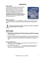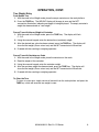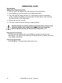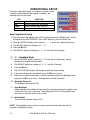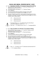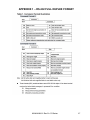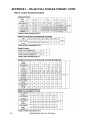
1
Digital Counting Scale
CS Series
Operation Manual
8526-M256-01 Rev B
07/10
Cardinal Scale Manufacturing Co.
PO BOX 151 WEBB CITY, MO 64870
PH (417) 673-4631 - FAX (417) 673-5001
www.detectoscale.com
8526-M256-O1
Rev B • CS
Series
Technical Support:
Ph: 866-254-8261
[email protected]
1
2
8526-M256-O1 Rev B • CS Series
TABLE OF CONTENTS
INSTALLATION . . . . . . . . . . . . . . . . . . . . . . . . . . . . . . . . . . . . . . . . . . . . . . . . .
PRECAUTIONS . . . . . . . . . . . . . . . . . . . . . . . . . . . . . . . . . . . . . . . . . . . . . . . .
CARE AND CLEANING . . . . . . . . . . . . . . . . . . . . . . . . . . . . . . . . . . . . . . . . . . .
KEY FUNCTIONS . . . . . . . . . . . . . . . . . . . . . . . . . . . . . . . . . . . . . . . . . . . . . . .
ANNUNCIATORS . . . . . . . . . . . . . . . . . . . . . . . . . . . . . . . . . . . . . . . . . . . . . . .
OPERATION . . . . . . . . . . . . . . . . . . . . . . . . . . . . . . . . . . . . . . . . . . . . . . . . . . .
Counting . . . . . . . . . . . . . . . . . . . . . . . . . . . . . . . . . . . . . . . . . . . . . . . . . . .
Tare Weight Entry . . . . . . . . . . . . . . . . . . . . . . . . . . . . . . . . . . . . . . . . . . . . .
Accumulator . . . . . . . . . . . . . . . . . . . . . . . . . . . . . . . . . . . . . . . . . . . . . . . . .
Quantity/Weight Hi Preset Limits . . . . . . . . . . . . . . . . . . . . . . . . . . . . . . . . . . .
OPERATIONAL SETUP . . . . . . . . . . . . . . . . . . . . . . . . . . . . . . . . . . . . . . . . . . .
CALIBRATION . . . . . . . . . . . . . . . . . . . . . . . . . . . . . . . . . . . . . . . . . . . . . . . . .
GRAVITY ADJUSTMENT . . . . . . . . . . . . . . . . . . . . . . . . . . . . . . . . . . . . . . . . . .
RS232 AND SERIAL PRINTER SETUP . . . . . . . . . . . . . . . . . . . . . . . . . . . . . . . .
ERROR AND STATUS DISPLAYS . . . . . . . . . . . . . . . . . . . . . . . . . . . . . . . . . . . .
BEFORE YOU CALL SERVICE . . . . . . . . . . . . . . . . . . . . . . . . . . . . . . . . . . . . . .
APPENDIX 1 – RS-232 FULL DUPLEX FORMAT . . . . . . . . . . . . . . . . . . . . . . . . . .
APPENDIX 2 – FIXED FORMAT RS-232 TRANSMISSION LINE ILLUSTRATION . . . .
APPENDIX 3 – ASCII CODE TABLE . . . . . . . . . . . . . . . . . . . . . . . . . . . . . . . . . . .
APPENDIX 4 – 7-SEGMENT DISPLAY CHARACTERS . . . . . . . . . . . . . . . . . . . . . .
1
2
2
3
5
7
8
9
10
11
12
18
19
20
26
26
27
29
30
31
FCC COMPLIANCE STATEMENT
WARNING! This equipment generates uses and can radiate radio frequency and if not
installed and used in accordance with the instruction manual, may cause interference to
radio communications. It has been tested and found to comply with the limits for a Class A
computing device pursuant to Subpart J of Part 15 of FCC rules, which are designed to
provide reasonable protection against such interference when operated in a commercial
environment. Operation of this equipment in a residential area may cause interference in
which case the user will be responsible to take whatever measures necessary to correct the
interference.
You may find the booklet "How to Identify and Resolve Radio TV Interference Problems"
prepared by the Federal Communications Commission helpful. It is available from the U.S.
Government Printing Office, Washington, D.C. 20402. The stock # is 001-000-00315-4.
All rights reserved. Reproduction or use, without expressed written permission, of editorial
or pictorial content, in any manner, is prohibited. No patent liability is assumed with respect
to the use of the information contained herein. While every precaution has been taken in the
preparation of this manual, the Seller assumes no responsibility for errors or omissions.
Neither is any liability assumed for damages resulting from use of the information contained
herein. All instructions and diagrams have been checked for accuracy and ease of
application; however, success and safety in working with tools depend to a great extent
upon the individual accuracy, skill and caution. For this reason the Seller is not able to
guarantee the result of any procedure contained herein. Nor can they assume responsibility
for any damage to property or injury to persons occasioned from the procedures. Persons
engaging the procedures do so entirely at their own risk.
8526-M256-O1 Rev B • CS Series
I3
INTRODUCTION
Thank you for purchasing our Detecto CS Series Digital Counting Scale. Your scale is
equipped with a rechargeable battery pack that is able to provide 100 hours continuous
operation (with backlight on) or 200 hours continuous operation (with backlight off).
This manual will guide you through setup and operation of your scale. Please read it
thoroughly before attempting to operate this scale and keep it handy for future reference.
SPECIFICATIONS
Displays:
(.75” High LCD,
with backlight)
WEIGHT = 5 Digits
PIECE WEIGHT = 5 Digits
COUNT = 6 Digits
Dimensions:
11.75" W x 12.63" D x 4.25" H (298mm x 321mm x 108mm)
Platform Size
11.38" W x 8.25" D (289mm x 210mm)
Model:
CS-6
CS-15
CS-30
CS-65
Capacity and Division Value
6 lb x .0005 lb (3 kg x .2g)
15 lb x .001 lb (7.5 kg x .5g)
30 lb x .002 lb (15 kg x 1g)
65 lb x .005 lb (30 kg x 2g)
Zero:
Established on power up routine and maintained by auto-zero circuitry
Power:
Built-in rechargeable battery pack or 115 VAC 50/60Hz or 230 VAC
50/60Hz
Tare:
100% of full scale capacity
Temperature:
32 ~ 104°F (0° ~ 40°C)
Humidity:
25% ~ 95% RH
Serial Number_____________________
PRECAUTIONS
Date of Purchase __________________
Before using this scale, read this manual
and pay special attention to all "WARNING"
symbols:
Purchased Form___________________
_________________________________
RETAIN THIS INFORMATION FOR FUTURE USE
4II
IIMPORTANT
8526-M256-O1 Rev B • CS Series
ELECTRICAL
WARNING
INSTALLATION
Unpacking
Before beginning installation of your CS Series Digital Counting Scale, make certain the
instrument has been received in good condition. Carefully remove the instrument from the
shipping carton and inspect it for any evidence of damage (such as exterior dents or
scratches) that may have taken place during shipment. Keep the carton and packing
material for return shipment if it should become necessary. It is the responsibility of the
purchaser to file all claims for any damages or loss incurred during transit.
Placement
Place the scale on a stable, vibration-free level surface away from direct sunlight and from
any rapidly moving air source (heating/cooling vents, fans, etc.). Make certain the power
cord and peripheral cables are routed out of the way of normal traffic.
CAUTION! DO NOT place the scale on any unstable cart, stand or table. The
scale may fall causing injury to the operator, and seriously damage the unit,
or proper operation of the scale may be inhibited.
Level Adjustment
Check to make certain the scale is level. The level indicator is
located at the front of the scale. If the scale is not level (the bubble
will not be centered), loosen the locking ring on all four (4) mounting
feet and adjust them as required to center the bubble and attain a
level scale. Once a level condition has been obtained, lock the
mounting feet in place by tightening the adjustment locking rings
against the bottom of the scale.
Not Level
Level
Power Connection
The scale contains a power supply that converts the 110/120/220/240 VAC 50/60Hz wall
supply to the power required by the scale circuitry. The power supply also contains the
circuitry necessary to monitor and recharge the battery and is capable of operating the scale
and recharging the battery simultaneously.
AC Operation
Plug the power cord into a grounded, polarized wall receptacle that supplies 110/120 VAC
50/60Hz power. If it is necessary to use an extension cord, make certain it is a 3-wire, fully
grounded type using a minimum of 18-gauge wire. Be certain the power cord is routed out
of the way of normal traffic. If only an ungrounded wall receptacle is available, it is the
customer’s responsibility to contact a qualified electrician to replace the ungrounded
receptacle with a properly grounded polarized wall receptacle or have a grounding adapter
properly installed.
CAUTION! To avoid electrical hazard, DO NOT under any circumstances,
cut, remove, alter, or in any way bypass the power cord-grounding prong.
It is the responsibility of the customer to contact a qualified electrician to install the
proper power cord connector. Plug the power cord into a grounded, polarized wall
receptacle that supplies 220/240 VAC 50/60Hz power. Be certain the power cord is routed
out of the way of normal traffic.
8526-M256-O1 Rev B • CS Series
1
PRECAUTIONS
Most scales are designed for an office type environment. The CS Series Digital Counting
Scale is no exception to that rule. The following should be used as a guideline for the
proper environment to operate your scale:
•
The environment should be free of excessive dust and moisture.
•
Provide a comfortable temperature. In general, the scale will perform well over a
temperature range of 32 to 104° F (0 to +40° C).
•
To keep cooling requirements to a minimum, the scale should be placed out of direct
sunlight and to provide adequate air circulation, keep the area around the scale clear.
•
Make certain the scale is not directly in front of a heating or cooling vent. Such a location
will subject the scale to sudden temperature changes and air currents that may result in
unstable weight readings.
•
Insure that the scale has good, clean AC power and is properly grounded. In areas
subject to lightning strikes, additional protection to minimize lightning damage, such as
surge suppressors, should be installed.
CARE AND CLEANING
1. DO NOT submerge the scale in water, pour or spray water directly on it.
2. DO NOT use acetone, thinner or other volatile solvents for cleaning.
3. DO clean the indicator with a damp soft cloth and mild non-abrasive detergent.
4. DO remove power before cleaning with a damp cloth.
5. DO clean and store the scale in a plastic bag (in a dry environment) if the scale is not
going to be used for some time. A desiccant packet may be included to prevent moisture
build up.
6. DO recharge the internal battery every three months while in storage.
2
8526-M256-O1 Rev B • CS Series
KEY FUNCTIONS
This section describes the use of each of the keys on the Digital Counting Scale. It will be
helpful to refer to the scale keyboard or the figure below when reading this section.
The membrane keyboard is not to be operated with pointed objects (pencils,
pens, fingernails, etc). Damage to keyboard resulting from this practice will
NOT be covered under warranty.
SAMPLE This key is used to weigh a known number of pieces in preparation for a new
counting operation. Sample quantities are entered using the numeric keypad in
SIZE
any quantity desired.
COUNT
PRESET
This key is used when setting the Quantity and Weight Preset limits. During a
counting operation (with the limits set) if the quantity or weight exceeds the
limits, the error beeper will sound and an error message will flash on the display.
SAMPLE Pressing this key will display the calculated average piece weight from the
WEIGHT current sampling and counting operation. It will also allow the manual entry of
a known average piece weight (using the numeric keys) to be used in the next
counting operation.
UNITS
Pressing this key will toggle the weighing units between pounds (lb) and
kilograms (kg). NOTE! The currently selected weighing unit is indicated by
illuminating either the lb or kg annunciator.
Æ0Å
ZERO
The ZERO key is used to perform a variety of functions depending on the
current mode of operation:
Weight Display Mode (lb or kg annunciator on): Pressing the ZERO key will set
the weight display to zero and turn on the ZERO annunciator if the displayed
weight is within ± 4% of scale capacity.
Calibration and Operational Setup Mode: Pressing the ZERO key and then
pressing the setup parameter number on the numeric keypad while "&% is
displayed will enter that setup mode.
8526-M256-O1 Rev B • CS Series
3
KEY FUNCTIONS, CONT.
M+
Pressing the M+ key will cause the scale to display the contents of the
accumulator (the number of pieces accumulated since the last time the
accumulator was cleared).
The M+ key is also used to add the current piece count value to the
accumulator. The M+ annunciator will be selected to indicate the accumulation
has taken place.
T
TARE
MC
0~9
A to Z
Space
(9)
x
CE
4
The TARE key is used to display the current tare weight (or zero if no tare has
been entered) and/or using the numeric keypad, to enter a new tare weight. It is
also used when entering a tare under a Preset number.
The MC key is used to clear the accumulator. The M+ and ADD annunciators
will turn off to indicate the clearing has taken place.
These keys are used to enter numeric data during normal operations as well as
during calibration and operational setup.
These keys are used to enter the letters A to Z and Space ( 9 ) for the
descriptions of ID’s and Items. Up to 12 digits can be used for the description.
This is the decimal point key. It is used to enter a decimal point where required
when entering numeric data.
The CE key is used to perform different functions depending on the current
mode of operation:
•
Data Entry: The CE key is used to clear an incorrect entry from the
display without processing the data. If an incorrect entry is made, press
the CE key and re-enter the correct data.
•
Count Mode: Pressing the CE key while in the Count mode will finish the
counting operation, update the quantity and weight accumulators and
return the scale to the Weight mode.
8526-M256-O1 Rev B • CS Series
ANNUNCIATORS
The annunciators are turned on to indicate that the scale is in the mode corresponding to the
annunciator label or that the status indicated by the label is active. The following describes
the functions of each annunciator.
Æ0Å (Center-of-Zero)
The Center-of-Zero annunciator is located to the left of the WEIGHT display and is selected
to indicate that the weight is within +/- 1/4 division of the center of zero.
NET
The NET annunciator is selected to show that the weight displayed is the net weight. Net
weight is determined by subtracting the stored tare weight from the gross or scale weight.
The tare weight, usually the weight of the container, is entered using the tare key. Note that
the NET annunciator is only active when a zero tare weight or tare weight value is stored
and the display is in the weight mode as shown by the illumination of the lb or kg
annunciator.
ADD
The ADD annunciator is located between the WEIGHT and PIECE WEIGHT display and is
selected to show that the sample is too small to calculate an accurate piece weight.
Increase the sample size to turn off the ADD annunciator.
INSUF SAMPLE
The INSUF SAMPLE annunciator is located between the WEIGHT and PIECE WEIGHT
display and is selected to show that the sample is too small to calculate an accurate piece
weight. If the counting function is continued without increasing the sample size, the scale
will still operate even though accuracy will be affected.
M+
The M+ annunciator is selected to show that the display is in the Accumulator mode and that
the value displayed is the current contents of the accumulator. Individual counts are
adjusted via the ( M+ ) and ( MC ) keys or optionally, any count may be entered using the
numeric keypad. Note that when both the M+ and ADD annunciators are selected, the
current count has been added to the accumulator.
[\ (Stable)
The (Stable) annunciator is located to the left of the COUNT display and is selected when
the WEIGHT display is stable.
PIECES
The PIECES annunciator is located on the right of the COUNT display and is selected when
the unit weight of the object on the platter is less than “Minimum Unit Weight”. The scale
can still count the quantity even though the unit weight is too small; however, this may affect
the counting accuracy.
8526-M256-O1 Rev B • CS Series
5
ANNUNCIATORS, CONT.
(Low Battery)
The Low Battery annunciator will turn on to indicate that the internal battery requires
charging. No change in operation will occur until just before the battery voltage drops to a
level where operation is affected. At this level, the scale will automatically turn itself off.
NOTE! When the battery needs to be recharged, the CHARGING LED will turn Red. After
the battery has been recharged, the CHARGING LED will turn Green.
kg
The kg annunciator is turned on to show that the weight displayed is in kilograms. The
UNITS key may be used to select kilogram as the weighing units.
lb
The lb annunciator is turned on to show that the weight displayed is in pounds. The UNITS
key may be used to select pounds as the weighing units.
6
8526-M256-O1 Rev B • CS Series
OPERATION
Power Switch
The Power Switch is located on the bottom left side
panel towards the front of the scale. Place the
power switch in the on position. The scale will
perform a brief lamp test. This test consists of
illuminating all display segments and annunciator
LED’s to allow the operator to make a visual
verification that the display is operational. After
completion of the lamp test, the scale will display the
model number and software revision level, then the
WEIGHT display will show zero weight, indicating
the scale is ready for use.
ON/OFF Switch
Metric Conversion
To change weighing units, press the UNITS key to toggle between pounds and kilograms.
Note that either the lb or kg annunciator will illuminate to indicate which weighing unit is
active.
Before using the scale, it should be “warmed up” (turned on and unloaded
for approximately 15 to 20 minutes).
WEIGHT Display
Displaying Weight
1. With the scale in the Weight mode (0 will be displayed for WEIGHT and will be
displayed for the PIECE WEIGHT and COUNT displays), place the item to be weighed
on the scale platform.
2. The display will show the weight on the scale platform. The lb or kg annunciators will
illuminate to indicate which unit of weight has been selected and that the scale is in the
Weight mode. Note that the PIECE WEIGHT and COUNT display will remain at 0
(zero).
Zero the WEIGHT Display
1. With the scale in the Weight mode ( will be displayed for the PIECE WEIGHT and
COUNT displays), press the ZERO key.
2. The WEIGHT display will show @@@@@@ (six dashes) for a few seconds and then
return to 0. The ZERO and Stable annunciators will illuminate, indicating a
center-of-zero, stable gross weight condition.
8526-M256-O1 Rev B • CS Series
7
OPERATION, CONT.
Counting
Weight of Sample is Unknown
1. With the scale in the Weight mode, place the sample on the scale platform.
2. On the numeric keypad, enter the number of pieces in the sample.
3. While the display is blinking, press the SAMPLE SIZE key.
4. Add the pieces to be counted and read the total count on the COUNT display.
5. Remove the pieces from the scale.
6. Press the CE key to complete the counting operation and return to the Weight mode.
Sample Weight is Known
1. With the scale in the Weight mode, using the numeric keypad, enter the piece weight of
the sample.
2. Press the SAMPLE WEIGHT key.
3. Add the pieces to be counted and read the total count on the COUNT display.
4. Remove the pieces from the scale.
5. Press the CE key to complete the counting operation and return to the Weight mode.
Counting With an Insufficient Sample
1. With the scale in the Weight mode, place the sample on the scale platform.
2. On the numeric keypad, enter the number of pieces in the sample.
3. While the display is blinking, press the SAMPLE SIZE key.
4. If the sample weight is too small, the INSUF SAMPLE and ADD annunciators will be
turned on and the COUNT display will show the number of pieces to be added.
5. Add the number of pieces requested. Note that if the pieces are not added the INSUF
SAMPLE annunciator will stay on to show the out-of-tolerance count.
6. Add the pieces to be counted and read the count.
7. Press the CE key to complete the counting operation and return to the Weight mode.
8
8526-M256-O1 Rev B • CS Series
OPERATION, CONT.
Tare Weight Entry
Push Button Tare
1. With the scale in the Weight mode, place the empty container on the scale platform.
2. Press the TARE key. The WEIGHT display will change to zero and the NET
annunciator illuminates, indicating net weight is being displayed. The empty container’s
weight has been entered as "tare weight".
Pre-set Tare with Known Weight of Container
1. With the scale in the Weight mode, press the TARE key. The display will flash
$9;.
2. Using the numeric keypad, enter the desired tare (container) weight.
3. After the desired tare value has been entered, press the TARE key. The display will
show the Net weight (Gross minus tare) and the NET annunciator will illuminate.
4. Proceed with the counting or weighing operation.
Pre-set Tare with Container on Scale
1. With the scale in the Weight mode, place the container on the scale.
2. Read the weight of the container.
3. Using the numeric keypad, enter the container weight.
4. After the container weight has been entered, press the TARE key. The display will
show the Net weight (Gross minus tare) and the NET annunciator will illuminate.
5. Proceed with the counting or weighing operation.
To Clear the Tare
To return to a zero tare, simply remove all material from the scale platform and press the
TARE key, which will reset the tare weight to zero.
8526-M256-O1 Rev B • CS Series
9
OPERATION, CONT.
Accumulator
Adding to the Weight Accumulator
1. With the scale in the Weight mode, place the item on the scale platform.
2. Press the M+ key to add to the value of the Weight Accumulator.
3. The PIECE WEIGHT display will flash 33, then change to show the accumulator
values (to indicate the addition to the accumulator has taken place). After 3 seconds,
the scale will return to the weight mode.
4. Remove the item from the scale.
5. The scale is ready for the next counting or weight operation.
Additional Weight Accumulator additions cannot take place until the current
weighing operation (scale weight returns to zero) has been completed.
Refer to Operational Setup, M+ Key Continuous Operation (1, 5).
Displaying the Accumulator
With the scale in the Weight mode, press the M+ key to display the content of the
accumulators. The values of the accumulator will be displayed for 3 seconds, then return
to the Weight mode display.
Clearing the Accumulator
Press the MC key. The accumulator will be reset to zero.
10
8526-M256-O1 Rev B • CS Series
OPERATION, CONT.
Quantity Preset Hi Limit
The scale can store a Quantity Preset Hi Limit value. The scale will beep and the unit
weight window will display a blinking @0&(@ if the quantity is over the Hi limit value set.
1. Press the COUNT PRESET key (items can be on scale or platform can be empty).
2. The WEIGHT display will change to show dashes (@@@@@).
3. Using the numeric keypad, enter the Quantity Preset Hi Limit.
4. Press the SAMPLE SIZE key, followed by the COUNT PRESET key.
5. The scale will return to the Weight mode.
Weight Preset Hi Limit
The scale can store a Weight Preset Hi Limit value. The scale will beep and the WEIGHT
display will show a blinking @! $*&@ if the weight is over the Hi limit value set.
1. Press the COUNT PRESET key (items can be on scale or platform can be empty).
2. The WEIGHT display will change to show dashes (@@@@@).
3. Using the numeric keypad, enter the Weight Preset Hi Limit.
4. Press the SAMPLE WEIGHT key, followed by the COUNT PRESET key.
5. The scale will return to the Weight mode.
Clear the Quantity and Weight Preset Hi Limits
To clear the Quantity and/or Weight Preset Hi Limit, simply enter a “0” for the limit value.
8526-M256-O1 Rev B • CS Series
11
OPERATIONAL SETUP
During the Operational Setup, it is necessary to enter values
using the scales alphanumeric keypad. In addition, the
following keys are also used:
KEY
• (decimal)
CE
TARE
MC
FUNCTION
Exit without saving setting
Move the cursor left (backward)
Move the cursor right (forward)
Enter (exit and save setting)
Enter Operational Setup
1. With the scale in the Weight mode (0 will be displayed for WEIGHT and will be
displayed for the PIECE WEIGHT and COUNT displays), press the ZERO key.
2. When the WEIGHT display shows dashes (@@@@@), press the • (decimal point) key.
3. The WEIGHT display will change to `0.
4. Press the MC key.
5. The WEIGHT display will change to 0` (with the first 0 flashing).
0` – Backlight Mode
1.
With the WEIGHT display showing 0` (with the first 0 flashing), use the
alphanumeric keypad to enter 0 and 1.
2.
The WEIGHT display will change to 0` with the 1 flashing.
3.
Press the MC key.
4.
The PIECE WEIGHT display will change to show the current setting.
5.
If the setting displayed is acceptable, press the MC key to save it.
6.
Otherwise, using the numeric keys, enter the desired setting for the Backlight Mode
and press the MC key to save it. Available values are 00, 01 and 02.
– Backlight Always On
The backlight will always be ON.
– Auto Backlight
While weighing, the backlight will be turned ON automatically when the weight is over
10 divisions or any key is pressed. The backlight will turn OFF automatically when
the scale has not been used for 10 minutes.
– No Backlight
The will be no backlight (always OFF).
NOTE! The backlight mode is stored in memory and will restored when the scale is
switched off and back on again.
12
8526-M256-O1 Rev B • CS Series
OPERATIONAL SETUP, CONT.
0` – Automatic Power-Off
1. With the WEIGHT display showing 0` with the 1 flashing, press the 2 key on
the alphanumeric keypad.
2. The WEIGHT display will change to 0` with the 2 flashing.
3. Press the MC key.
4. The PIECE WEIGHT display will change to show the current setting.
5. If the setting displayed is acceptable, press the MC key to save it.
6. Otherwise, using the numeric keys, enter a desired value for the scale to be
automatically turned OFF when it is not in use and press the MC key to save it.
Available values are from 1 to 10 minutes. Note that entering 00 will disable the auto
power-off function.
0` – Stable Range for Quantity Sample
1. With the WEIGHT display showing 0` with the 2 flashing, press the 3 key on
the alphanumeric keypad.
2. The WEIGHT display will change to 0` with the 3 flashing.
3. Press the MC key.
4. The PIECE WEIGHT display will change to show the current setting.
5. If the setting displayed is acceptable, press the MC key to save it.
6. Otherwise, using the numeric keys, enter a desired value for the Stable Range for
Quantity Sample and press the MC key to save it. Available values are from 00 to 15.
NOTE! Selecting a larger number makes the sampling faster, but less accurate.
Also, selecting a smaller number makes the sampling slower, but more accurate.
0` – Automatic Average Unit Weight
1. With the WEIGHT display showing 0` with the 3 flashing, press the 4 key on
the alphanumeric keypad.
2. The WEIGHT display will change to 0` with the 4 flashing.
3. Press the MC key.
4. The PIECE WEIGHT display will change to show the current setting.
5. If the setting displayed is acceptable, press the MC key to save it.
6. Otherwise, select the desired setting for the Automatic Average Unit Weight and
press the MC key to save it.
– No Automatic Average Unit Weight Function
Press the SAMPLE key for manual unit weight calibration.
– Automatic Average Unit Weight Function
If counting data increases over 10% compared with the previous sampling value,
and the increase is less than 100% of previous sampling value, the automatic unit
weight calibration will be proceed again.
8526-M256-O1 Rev B • CS Series
13
OPERATIONAL SETUP, CONT.
0` – A/D Sampling Speed
1. With the WEIGHT display showing 0` with the 4 flashing, press the 5 key on
the alphanumeric keypad.
2. The WEIGHT display will change to 0` with the 5 flashing.
3. Press the MC key.
4. The PIECE WEIGHT display will change to show the current setting.
5. If the setting displayed is acceptable, press the MC key to save it.
6. Otherwise, select the desired setting for the A/D Sampling Speed and press the MC
key to save it.
– Low Speed
Low speed is about 7.5 Hz. (Weighing reflection is slow but relatively stable).
– Fast Speed
Fast speed is about 14 Hz. (Weighing reflection is fast but relatively not stable).
0` – Zero Display Range
1. With the WEIGHT display showing 0` with the 5 flashing, press the 6 key on
the alphanumeric keypad.
2. The WEIGHT display will change to 0` with the 6 flashing.
3. Press the MC key.
4. The PIECE WEIGHT display will change to show the current setting.
5. If the setting displayed is acceptable, press the MC key to save it.
6. Otherwise, select the desired setting for the Zero Display Range and press the MC
key to save it.
= Display All
= Zero range ± 1 bit will not display division, and displays zero instead.
= Zero range ± 2 bits will not display division, and displays zero instead.
= Zero range ± 3 bits will not display division, and displays zero instead.
If is set, when setting up Pre-Tare data, the Pre-Tare data can not be less or
equal to ±3 bits external value, and so on. When the weight is over 1/3 full capacity
and return to 0, this function will be started.
14
8526-M256-O1 Rev B • CS Series
OPERATIONAL SETUP, CONT.
0` – Zero Tracking Range
1. With the WEIGHT display showing 0` with the 6 flashing, press the 7 key on
the alphanumeric keypad.
2. The WEIGHT display will change to 0` with the 7 flashing.
3. Press the MC key.
4. The PIECE WEIGHT display will change to show the current setting.
5. If the setting displayed is acceptable, press the MC key to save it.
6. Otherwise, select the desired setting for the Zero Tracking Range and press the MC
key to save it.
= After weight is stable for over 1 second, it could track ±1/4d (external value is 1/4 bit).
= After weight is stable for over 1 second, it could track ±1/2d (external value is 1/2 bit).
= After weight is stable for over 1 second, it could track ±1d (external value is 1 bit).
= After weight is stable for over 1 second, it could track ±2d (external value is 2 bits).
NOTE! The zero tracking function will be started only if the Gross weight is at 0.
0` – Accumulation Ending Mode
1. With the WEIGHT display showing 0` with the 7 flashing, press the 8 key on
the alphanumeric keypad.
2. The WEIGHT display will change to 0` with the 8 flashing.
3. Press the MC key.
4. The PIECE WEIGHT display will change to show the current setting.
5. If the setting displayed is acceptable, press the MC key to save it.
6. Otherwise, select the desired setting for the Accumulation Ending Mode and press the
MC key to save it.
= Press the M+ key. After screen displays accumulation data for 3 seconds, the scale
will return to the Weight mode.
= Press the M+ key. After screen displays accumulation data, the scale will not return
to the Weight mode until the CE key is pressed.
= Press the M+ key. The screen does not display accumulation data. The beeper will
“beep” once.
8526-M256-O1 Rev B • CS Series
15
OPERATIONAL SETUP, CONT.
0` – Pre-Tare Mode
1. With the WEIGHT display showing 0` with the 8 flashing, press the 9 key on
the alphanumeric keypad.
2. The WEIGHT display will change to 0` with the 9 flashing.
3. Press the MC key.
4. The PIECE WEIGHT display will change to show the current setting.
5. If the setting displayed is acceptable, press the MC key to save it.
6. Otherwise, select the desired setting for the Pre-Tare Mode and press the MC key to
save it.
= Pre-Tare can not proceed when there is weight on the platter. When there is no
weight on the platter, press the TARE key to enter the Pre-Tare value, and then
press the TARE key again to complete.
= Pre-Tare can proceed when there is weight on the platter (enter digit in the unit
weight column and then press the TARE key).
When there is weight on the scale, enter Pre-Tare data in the unit weight column.
Example: enter “1”, “1.0”, “1.00” or “1.000” and then press the TARE key again to
complete the Pre-Tare “1kg”.
Pre-Tare value can not be more than maximum weighing value, or the first and second
segment point of division. Also, the value can not be less than or equal to the external
value set up in "`.
0` – Beeper Sound Output Condition Under Quantity Mode
1. With the WEIGHT display showing 0` with the 9 flashing, press the 0 key,
the CE key and then the 1 key on the alphanumeric keypad.
2. The WEIGHT display will change to 0` with the 0 flashing.
3. Press the MC key.
4. The PIECE WEIGHT display will change to show the current setting.
5. If the setting displayed is acceptable, press the MC key to save it.
6. Otherwise, select the desired setting for the Beeper Sound Output Condition Under
Quantity Mode and press the MC key to save it.
= If the weighing quantity exceeds quantity setting (or weight exceeds weight setting),
the beeper will sound when the weight is unstable.
= If the weighing quantity exceeds quantity setting (or weight exceeds weight setting),
and it doesn’t matter if the weight is stable, the beeper will sound automatically.
16
8526-M256-O1 Rev B • CS Series
OPERATIONAL SETUP, CONT.
0` – Accumulation Acceptable Condition 1
1. With the WEIGHT display showing 0` with the 0 flashing, press the 1 key on
the alphanumeric keypad.
2. The WEIGHT display will change to 0` with the right 1 flashing.
3. Press the MC key.
4. The PIECE WEIGHT display will change to show the current setting.
5. If the setting displayed is acceptable, press the MC key to save it.
6. Otherwise, select the desired setting for the Accumulation Acceptable Condition 1
setting and press the MC key to save it.
= The scale will accept accumulation only when the weight is stable.
= The scale will accept accumulation no matter if the weight is stable or not.
0` – Accumulation Acceptable Condition 2
1. With the WEIGHT display showing 0` with the second 1 flashing, press the 2
key on the alphanumeric keypad.
2. The WEIGHT display will change to 0` with the 2 flashing.
3. Press the MC key.
4. The PIECE WEIGHT display will change to show the current setting.
5. If the setting displayed is acceptable, press the MC key to save it.
6. Otherwise, select the desired setting for the Accumulation Acceptable Condition 2
setting and press the MC key to save it.
= The scale will only accept the next accumulation data when the weight returns to zero.
= The scale will accept the next accumulation data no matter if the weight returns to
zero or not. When there is a load on the scale, the weight can be accumulated
continuously.
= The weight must return to zero Gross weight before the scale can accept the next
accumulation data.
Operational Setup is Complete
1. With the WEIGHT display showing 0` with the 2 flashing, press the • (decimal
point) key.
2. The WEIGHT display will change to `0.
3. Press the • (decimal point) key again.
4. The scale will return to the Weight mode (0 will be displayed for WEIGHT and will be displayed for the PIECE WEIGHT and COUNT displays).
5. The scale is ready for normal use.
8526-M256-O1 Rev B • CS Series
17
CALIBRATION
During the Calibration process, it is necessary to enter values
using the scales alphanumeric keypad. In addition, the
following keys are also used:
KEY
• (decimal)
CE
TARE
MC
FUNCTION
Exit without saving setting
Move the cursor left (backward)
Move the cursor right (forward)
Enter (exit and save setting)
Enter Calibration
1.
With the scale in the Weight mode (0 will be displayed for WEIGHT and will be
displayed for the PIECE WEIGHT and COUNT displays), press the ZERO key.
2.
When the WEIGHT display shows dashes (@@@@@), press the • (decimal point) key.
3.
The WEIGHT display will change to `0. Press the TARE key.
4.
The WEIGHT display will change to `4. Press the MC key.
5.
The WEIGHT display will change to ` (with the first 0 flashing).
6.
Use the alphanumeric keypad to enter 0 and 1. The WEIGHT display will change
to ` with the 1 flashing.
Press the MC key. The WEIGHT display will change to show 0 and the
COUNT display will show the zero weight count.
7.
8.
Make sure that there is no load on the platter and press the MC key.
9.
Both the WEIGHT and COUNT display will change to dashes (@@@@@). After a few
seconds, the COUNT display will return to the zero weight count and the WEIGHT
display will prompt for the weight to be used for calibration. EXAMPLE: For a CS30
the WEIGHT display will flash 0 lb.
NOTE! To calibrate the scale with a different weight value than the prompted
amount, use the alphanumeric keypad to enter the new weight value. EXAMPLE:
To calibrate a CS30 with 10 lbs instead of 30 lbs, enter 1,0,0,0,0. Note that the new
value can not exceed the capacity of the scale.
10. Place the test weight on the scale platter. The WEIGHT display will change to the
value of the test weight and the COUNT display will show the equivalent weight count.
11. Wait a few seconds for the platter to stabilize and press the MC key.
12. Both the WEIGHT and COUNT displays will change to dashes (@@@@@) for a few
seconds and then the WEIGHT display will change to ` with the 1 flashing.
13. Remove the test weights from the scale platter and press the • (decimal point) key.
14. The WEIGHT display will change to `4. Press the • (decimal point) key again.
15. The scale will return to the Weight mode (0 will be displayed for WEIGHT and will be displayed for the PIECE WEIGHT and COUNT displays).
16. The scale is ready for normal use.
18
8526-M256-O1 Rev B • CS Series
GRAVITY ADJUSTMENT
IMPORTANT! This scale is equipped with a Gravity Adjustment function which
allows the scale to be calibrated in one location and then adjusted to match the
gravity at the location where it will be used.
During the Gravity Adjustment process, it is necessary to enter
values using the scales alphanumeric keypad. In addition, the
following keys are also used:
KEY
• (decimal)
CE
TARE
MC
FUNCTION
Exit without saving setting
Move the cursor left (backward)
Move the cursor right (forward)
Enter (exit and save setting)
Enter Gravity Adjustment
1.
With the scale in the Weight mode (0 will be displayed for WEIGHT and will be
displayed for the PIECE WEIGHT and COUNT displays), press the ZERO key.
2.
When the WEIGHT display shows dashes (@@@@@), press the • (decimal point) key.
3.
The WEIGHT display will change to `0. Press the TARE key.
4.
The WEIGHT display will change to `4. Press the MC key.
5.
The WEIGHT display will change to ` (with the first 0 flashing).
6.
Use the alphanumeric keypad to enter 0 and 2.
7.
The WEIGHT display will change to ` with the 2 flashing.
8.
Press the MC key.
9.
The PIECE WEIGHT display will change to show the current number of times the
gravity adjustment has been changed and the COUNT display will show the current
gravity adjustment value.
10. Press the MC key.
11. The first digit on the COUNT display will start to flash.
12. Use the alphanumeric keypad to enter the new gravity adjustment value.
13. Press the MC key.
14. The WEIGHT display will change to `4.
15. Press the • (decimal point) key.
16. The scale will return to the Weight mode (0 will be displayed for WEIGHT and will be displayed for the PIECE WEIGHT and COUNT displays).
17. The scale is ready for normal use.
NOTE! By default, the USA gravity adjustment value will be used. Consult the factory
Tech Support for the gravity adjustment value for your location.
8526-M256-O1 Rev B • CS Series
19
RS232 AND SERIAL PRINTER SETUP
During the RS232 and Serial Printer Setup, it is necessary to
enter values using the scales alphanumeric keypad. In
addition, the following keys are also used:
KEY
• (decimal)
CE
TARE
MC
FUNCTION
Exit without saving setting
Move the cursor left (backward)
Move the cursor right (forward)
Enter (exit and save setting)
Enter RS232 and Serial Printer Setup
1.
With the scale in the Weight mode (0 will be displayed for WEIGHT and will be
displayed for the PIECE WEIGHT and COUNT displays), press the ZERO key.
2.
When the WEIGHT display shows dashes (@@@@@), press the • (decimal point) key.
3.
The WEIGHT display will change to `0. Press the TARE key.
4.
The WEIGHT display will change to `4. Press the TARE key again.
5.
The WEIGHT display will change to `9:. Press the MC key.
6.
The WEIGHT display will change to 9:` (with the first 0 flashing).
9:` – Baud Rate Setting
1.
2.
3.
4.
5.
6.
20
With the WEIGHT display showing 9:` (with the first 0 flashing), use the
alphanumeric keypad to enter 0 and 1.
The WEIGHT display will change to 9:` with the 1 flashing.
Press the MC key.
The PIECE WEIGHT display will change to show the current setting.
If the setting displayed is acceptable, press the MC key to save it.
Otherwise, using the numeric keys, enter the desired setting for the Baud Rate and
press the MC key to save it. Available values are 00 through 05.
` =
600 bits/second
` =
1200 bits/second
` =
2400 bits/second
` =
4800 bits/second
` =
9600 bits/second
` =
19200 bits/second
8526-M256-O1 Rev B • CS Series
RS232 AND SERIAL PRINTER SETUP, CONT.
9:` – Communication Protocol Setting
1.
2.
3.
4.
5.
6.
With the WEIGHT display showing 9:` (with the 1 flashing), use the
alphanumeric keypad to enter 0 and 2.
The WEIGHT display will change to 9:` with the 2 flashing.
Press the MC key.
The PIECE WEIGHT display will change to show the current setting.
If the setting displayed is acceptable, press the MC key to save it.
Otherwise, using the numeric keys, enter the desired setting for the Communication
Protocol and press the MC key to save it. Available values are 00 through 02.
` =
N, 8, 1
` =
E,7, 1
` =
O, 7, 1
9:` – Output Data Format Setting
1.
2.
3.
4.
5.
6.
With the WEIGHT display showing 9:` (with the 2 flashing), use the
alphanumeric keypad to enter 0 and 3.
The WEIGHT display will change to 9:` with the 3 flashing.
Press the MC key.
The PIECE WEIGHT display will change to show the current setting.
If the setting displayed is acceptable, press the MC key to save it.
Otherwise, using the numeric keys, enter the desired setting for the Output Data
Format and press the MC key to save it. Available values are 00 through 07.
` =
Fixed format 1 (details on the next page)
` =
Fixed format 2 (details on the next page)
` =
Reserved
` =
Same as screen display (general format)
` =
Same as screen display (simple format)
` =
Gross weight (general format)
` =
Net weight (general format)
` =
Tare (general format)
8526-M256-O1 Rev B • CS Series
21
RS232 AND SERIAL PRINTER SETUP, CONT.
Example: Illustration for fixed format is described as follows:
22
8526-M256-O1 Rev B • CS Series
RS232 AND SERIAL PRINTER SETUP, CONT.
9:` – Output Counts Setting per Second in Continuous Transmission
1.
2.
3.
4.
5.
6.
With the WEIGHT display showing 9:` (with the 3 flashing), use the
alphanumeric keypad to enter 0 and 4.
The WEIGHT display will change to 9:` with the 4 flashing.
Press the MC key.
The PIECE WEIGHT display will change to show the current setting.
If the setting displayed is acceptable, press the MC key to save it.
Otherwise, using the numeric keys, enter the desired setting for the Output Counts per
Second in Continuous Transmission and press the MC key to save it. Available
values are 00 through 04.
` =
1 count/second
` =
2 counts/second
` =
4 counts/second
` =
8 counts/second
` =
More than 8 counts/second
•
If 9:` is set as (fixed format 1) or (fixed format 2), the continuous
transmission mode may only work with short distances.
•
If 9:` is set as (Reserved), continuous transmission mode is not
available.
•
If 9:` is set as through , continuous transmission mode is available.
8526-M256-O1 Rev B • CS Series
23
RS232 AND SERIAL PRINTER SETUP, CONT.
9:` – Operation Mode Setting
1.
2.
3.
4.
5.
6.
With the WEIGHT display showing 9:` (with the 4 flashing), use the
alphanumeric keypad to enter 0 and 5.
The WEIGHT display will change to 9:` with the 5 flashing.
Press the MC key.
The PIECE WEIGHT display will change to show the current setting.
If the setting displayed is acceptable, press the MC key to save it.
Otherwise, using the numeric keys, enter the desired setting for the Operation Mode
and press the MC key to save it. Available values are 00 through 04.
` =
Command mode
` =
Continuous transmission and command mode
` =
Automatic transmission and command mode
` =
Manual transmission and command mode
Press M+ or MC key to do manual transmission.
` =
No RS-232 transmission
•
If 9:` is set as (Reserved), the setting of c`9:` will be fixed as
manual transmission but without command mode.
•
For an illustration of command mode format, refer to “Appendix 1”.
9:` – Continuous Transmission Output Condition Setting
1.
2.
3.
4.
5.
6.
With the WEIGHT display showing 9:` (with the 5 flashing), use the
alphanumeric keypad to enter 0 and 6.
The WEIGHT display will change to 9:` with the 6 flashing.
Press the MC key.
The PIECE WEIGHT display will change to show the current setting.
If the setting displayed is acceptable, press the MC key to save it.
Otherwise, using the numeric keys, enter the desired setting for the Continuous
Transmission Output Condition and press the MC key to save it. Available values are
00 or 01.
•
24
` =
Output all
` =
No output under OL or unstable condition
The 9:` setting will only be effective when 9:` is set as “continuous transmission mode”.
8526-M256-O1 Rev B • CS Series
RS232 AND SERIAL PRINTER SETUP, CONT.
9:` – Zero Reset Condition for Automatic Transmission Setting
1.
2.
3.
4.
5.
6.
With the WEIGHT display showing 9:` (with the 6 flashing), use the
alphanumeric keypad to enter 0 and 7.
The WEIGHT display will change to 9:` with the 7 flashing.
Press the MC key.
The PIECE WEIGHT display will change to show the current setting.
If the setting displayed is acceptable, press the MC key to save it.
Otherwise, using the numeric keys, enter the desired setting for the Zero Reset
Condition for Automatic Transmission Condition and press the MC key to save it.
Available values are 00 through 02.
` =
External value “0d”
` =
External value “0d”
` =
External value “0d”
•
The range setting of 9:` is related to the zero reset setting in
accumulation acceptable condition in 0`.
•
Only if the 9:` setting is set as will 9:` setting be effective.
9:` – Reset Condition for Automatic Transmission Setting
1.
2.
3.
4.
5.
6.
With the WEIGHT display showing 9:` (with the 7 flashing), use the
alphanumeric keypad to enter 0 and 8.
The WEIGHT display will change to 9:` with the 8 flashing.
Press the MC key.
The PIECE WEIGHT display will change to show the current setting.
If the setting displayed is acceptable, press the MC key to save it.
Otherwise, using the numeric keys, enter the desired setting for the Zero Reset
Condition for Automatic Transmission Condition and press the MC key to save it.
Available values are 00 through 02.
•
` =
External value “0d”
` =
External value “0d”
` =
External value “0d”
Only if 9:` setting is set as “automatic transmission mode” will
9:``setting be effective
8526-M256-O1 Rev B • CS Series
25
ERROR AND STATUS DISPLAYS
The Digital Counting Scale is equipped with a diagnostic software program that tests various
portions of the instrument’s circuitry and verifies proper operation. Should a problem be
detected, an error or status message will be displayed alerting the operator to that condition.
The following lists these errors and status displays and their meaning:
Display
@&(@`
Meaning
QtY – During a counting operation, this message is flashed to indicate the
quantity of items on the scale exceeds the Quantity Preset Hi Limit value. The
error beeper will also sound on and off.
@! $*&@` WPSt – During a counting operation, this message is flashed to indicate the
weight of items on the scale exceeds the Weight Preset Hi Limit value. The
error beeper will also sound on and off.
Left Arrow - This symbol is used by the scale to indicate which annunciator is
active. Note that this applies to the annunciator labels on the display overlay.
@@#!@
Over Load - Indicates the scale weight capacity has been exceeded. The
error beeper will also sound on and off until the Over Load condition is
corrected.
*1008
SAMP - Indicates the scale is weighing the sample.
Low Battery - Indicates the internal battery requires charging.
BEFORE YOU CALL FOR SERVICE
The Digital Counting Scale has been designed to provide you with years of trouble-free
operation. In spite of this, troubles sometimes happen. Before calling for service assistance
you should make some initial checks to verify that a problem does exist. The following
describes several types of symptoms along with suggested remedies.
Problem
Display does not turn on
Possible Solutions
AC Operation:
Is the AC power cord fully inserted into the wall
receptacle? Check wall receptacle for proper AC
power. Try another electrical appliance in the same
receptacle, does it work? Check the circuit
breaker. Has there been power failure.
Battery operation:
Check if battery is installed and installed correctly.
Is battery discharged? Recharge or replace
battery.
Incorrect weight displayed
26
Insure that the scale platform isn't touching an
adjacent object. Have proper operation procedures
been followed?
8526-M256-O1 Rev B • CS Series
APPENDIX 1 – RS-232 FULL DUPLEX FORMAT
8526-M256-O1 Rev B • CS Series
27
APPENDIX 1 – RS-232 FULL DUPLEX FORMAT, CONT.
28
8526-M256-O1 Rev B • CS Series
APPENDIX 2 – FIXED FORMAT RS-232 TRANSMISSION
LINE ILLUSTRATION
8526-M256-O1 Rev B • CS Series
29
APPENDIX 3 – ASCII CODE TABLE
30
8526-M256-O1 Rev B • CS Series
APPENDIX 4 – 7-SEGMENT DISPLAY CHARACTERS
8526-M256-O1 Rev B • CS Series
31
32
8526-M256-O1 Rev B • CS Series