1
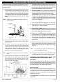
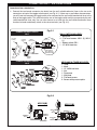
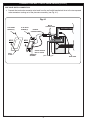
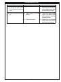
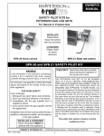
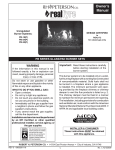
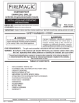
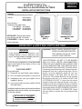
OWNER'S
MANUAL
WALL SWITCH AND MECHANICAL TIMER
INSTALLATION INSTRUCTIONS
GENERAL
Installed on the following Peterson products:
Pilot Kits -
(For baseboard wall)
• APK-10(M)(P)
• APK-11(M)(P)
• EPK-01(M)(P)
Burner Systems (w/Remote Compatible Valves)
• G45 SERIES • G9 SERIES
• G46 SERIES • G10 SERIES
• G8 SERIES • G18 SERIES
INSTALLER: Please leave these
instructions with the consumer.
CONSUMER: Please retain for
future reference.
Wall switch
(WS-1)
Mechanical timer
(WS-2)
MODELS WS-1 and WS-2 WALL SWITCH AND TIMER
Important: READ THESE INSTRUCTIONS
CAREFULLY BEFORE STARTING
THE INSTALLATION OF YOUR
LOG SET AND CONTROL.
WARNING
If the information in this manual is not
followed exactly, a fire or explosion may
result, causing property damage, personal
injury, or loss of life.
Do not store or use gasoline or other flammable
vapors and liquids in the vicinity of this or any
other appliance.
FOR YOUR SAFETY
If you smell gas:
1. Extinguish any open flame; open windows.
2. Don’t use electrical switches or your phone.
3. Immediately call your gas supplier from a
neighbor’s phone.
4. If you cannot reach your gas supplier, call the
fire department.
Installation and service must be performed by a
qualified professional installer, service agency,
or the gas supplier.
YOUR PETERSON LOG SET IS TO BE BURNED
ONLY IN A FULLY VENTED, NONCOMBUSTIBLE
FIREPLACE WITH DAMPER AND CHIMNEY FREE
OF ANY OBSTRUCTIONS. THE FIREPLACE MUST
BE DESIGNED AND APPROVED TO BURN WOOD.
Like burning natural firewood, your Peterson log set is
designed to burn with a yellow smoky flame. For this
reason, it must be adequately vented. Be sure your
fireplace damper is fully open when you burn your
gas log set. The smallest dimension of the chimney
flue must be at least 8". If it is smaller, DO NOT USE
A PETERSON LOG SET. If fumes from the burner
emerge into the room when the damper is fully open,
creating a smell like a smoldering oil lamp, it indicates
that the fireplace draft is defective. Check the chimney
flue for obstructions. DO NOT OPERATE LOGS UNTIL
THE FIREPLACE DRAFT IS CORRECTED. Check
with your dealer or installer. Do not use firewood with
this unit.
INSTALLER & CONSUMER
These instructions MUST be
retained with this appliance.
ROBERT H. PETERSON CO. • 14724 East Proctor Avenue • City of Industry, California 91746
REV 2-1005281303
1
L-A2-017
INSTALLATION AND OPERATING INSTRUCTIONS
Be sure all cautions and warnings are observed in your APK
and burner system installation and operating instructions.
5. Remove the weight or the chain from the plumb line. Tie
one end of the wire cable to the plumb line and pull the
plumb line back up through the wall switch/mechanical
timer location to expose several inches of wire.
INSTALLATION
1. Select a location for the wall switch/mechanical timer
near the fireplace and between the wall studs (see Fig.
2-2). To ensure sufficient millivoltage between the
wall switch/mechanical timer and the pilot generator,
no more than 15' of wire should be used between
the wall switch/mechanical timer and the safety
valve.
Note:
6. For the wall switch, attach the wire to the side terminal
screws, connecting one spade clip to each terminal screw.
Tighten the terminal screws securely (see page 3).
For the timer, pass the wires into the connection
chamber (see Connecting Mechanical Timer, Fig. 31, page 3), ensuring they go through into the second
chamber. Using the screw with pressure plate, securely
fasten wires into place.
Safety valve is supplied in the Peterson APK and
burner systems.
7. Attach the wall switch/mechanical timer to a switch box.
Switch/timer
location
8. Attach the wall cover to the wall switch/mechanical
timer with the 1/4" machine screws.
Plumbline
9. MECHANICAL TIMER ONLY: Attach the mechanical
timer face cover to the wall cover using the face cover
nut provided. Align knob and press in place.
10. Remove the unattached female connectors located
on the outside male connectors of the toggle switch
control (Fig. 3-1). Strip approximately 1/4" of installation
from the end of the wire at the baseboard (Fig. 21). Crimp the unattached female connectors onto the
stripped wire.
1/2" diameter
hole
Fig. 2-1
2. At the wall switch/mechanical timer location selected,
cut out a clearance hole for direct wall or switch
box mounting.
11. Run the wire with the female connectors to the toggle
switch control. Attach the female connectors to the
outside male connectors of the toggle switch control
(Fig. 3-1).
3. Tie about 6" of chain or a small weight to a cord to
create a plumb line. Hang the plumb line from the
wall switch/mechanical timer location to the top of the
wall baseboard. Immediately below the wall switch/
mechanical timer location, as indicated by the plumb
line, drill a 1/2" to 3/4" hole (see Fig. 2-1).
Note:
Note:
Do not hook up electricity to this unit (millivolts
only).
This unit does not require an outside electrical
source (millivolt system only).
12. The toggle switch control must be in the OFF position
in order to operate the wall switch/mechanical timer.
4. Lower the plumb line through the switch/timer location
hole, within the stud space, down to the baseboard
level. Pull the chain or the weight out of the 1/2" to 3/4"
hole at the baseboard using a stiff hooked wire (a bent
wire coat hanger works well).
OPERATING YOUR PETERSON GAS LOG SET WITH
THE WALL SWITCH OR MECHANICAL TIMER
Wall Switch:
To turn on your log set with the wall switch, turn the wall
switch to the ON position and the log set will light. To turn
off your log set, turn the wall switch to the OFF position. The
log set will extinguish and the pilot will remain lit.
Wall switch or
mechanical timer
Wire
Mechanical Timer:
To turn on your log set with the mechanical timer, turn the
timer knob clockwise to the time setting desired. The timer
will keep your log set lit for up to 60 minutes. Following the
expiration of the time set, your log set will extinguish and
the pilot will remain lit.
Valve
FOR YOUR SAFETY, never leave your log set operating
unattended.
Fig. 2-2
REV 2-1005281303
2
L-A2-017
CONNECTING WS-1 / WS-2 WIRE LEADS
TOGGLE SWITCH CONNECTION
1. Connect the two female connector wire leads from the wall switch/mechanical timer to the two male
connectors on back of the toggle switch control (see Fig. 3-1). If there are no available male connectors,
you will have to disconnect the toggle switch wires and connect the wall switch/mechanical timer to the
back of the toggle switch. This will eliminate the use of the toggle switch and let you operate by the wall
switch/mechanical timer only. You can also choose to cut and strip the wall switch/mechanical timer
female wire leads and directly attach to the valve terminals (see Fig. 3-2).
Fig. 3-1
CONNECTING WALL SWITCH
WS-1
FLAT HEAD
SCREW (2)
FLAT HEAD
SCREW (2)
MALE
CONNECTORS
FEMALE
CONNECTORS
TOGGLE
SWITCH
CONTROL
ON
OFF
MS-2
FEMALE
CONNECTOR
MS-1
MALE
CONNECTORS
WIRE LEADS TO
WALL SWITCH OR
MECHANICAL TIMER
CABLE LENGTH
NOT TO SCALE
WALL
PLATE
WALL SWITCH INCLUDES:
1 - Wall plate
4 - Flat head screws- MS-1 (2), MS-2
(1)
1 - Rocker switch- RS-1
1 - 15' 18GA lead wire
TERMINAL
SCREWS
CONNECTING WALL SWITCH
WS-2
MECHANICAL TIMER INCLUDES:
1 - Timer
1 - Knob
1 - 15' 18GA lead wire
1 - Nut
1 - Face cover
1 - Wall plate
2 - Flat head screws
2 - Screws with pressure plate
Fig. 3-2
APK 10(M)
WIRE LEADS
TO
SWITCH
REV 2-1005281303
OF
WIRE LEADS
TO
SWITCH
F
PG
ON
TH
PG
WIRE LEADS
TO
GENERATOR
IN
OT
PIL
APK 11(M)
WIRE LEADS
TO
GENERATOR
3
L-A2-017
CONNECTING WS-1 / WS-2 WIRE LEADS (CONT.)
PINE CONE SWITCH CONNECTION
1. Connect the two female connector wire leads from the wall switch/mechanical timer to the two exposed
male connectors coming out of the pine cone assembly (see Fig. 4-1).
Fig. 4-1
FLAT HEAD
SCREW (2)
MS-2
WALL
PLATE
REV 2-1005281303
FLAT HEAD
SCREW (2)
MALE
CONNECTORS
FEMALE
CONNECTORS
MS-1
CABLE LENGTH
NOT TO SCALE
TERMINAL
SCREWS
4
PINE CONE
L-A2-017
TROUBLESHOOTING
Problem
Cause
Solution
1. Burner does not light when
pressing the wall switch
or turning the mechanical
timer.
a. Loose wires
a. Check wire leads to the wall
switch/mechanical timer and
to the toggle switch. Make
sure the fittings are tight.
2. Burner is on and will not shut
off.
b. Toggle switch is in the ON
position.
b. Toggle switch control needs
to be in the OFF position
when using the wall switch/
mechanical timer.
c. A short in the wires.
c. Check wires for barespots
and the ends of the wires to
see if they are touching.
REV 2-1005281303
5
L-A2-017
WARRANTY
PETERSON VENTED GAS LOG SETS
LIMITED WARRANTY
All Peterson gas logs are WARRANTED for as long as you own them (lifetime).
All Peterson burner assemblies are WARRANTED for TEN (10) YEARS.
SPK-26 controls are covered by a THREE (3) YEAR “All Parts” Warranty.
All other Peterson valves, pilots, and controls are covered by a ONE (1) YEAR Limited Warranty (excluding batteries).
PLEASE KEEP A COPY OF YOUR SALES SLIP FOR PROOF OF PURCHASE
This warranty applies to the original purchaser and to single family residential use only. It commences from date of purchase, and is valid only with
proof of purchase.
This warranty does not cover parts becoming defective through misuse, accidental damage, electrical damage, improper handling, storage, and/or
installation. Product must be installed (and gas must be connected) as specified in the instructions or operator’s manual, by a qualified professional
installer. Accessories, parts, valves, remotes, etc., when used must be Peterson Co. product.
This warranty does not apply to rust, corrosion, oxidation, or discoloration, unless the affected component becomes inoperable. It does not cover
labor or labor-related charges.
This warranty specifically excludes liability for indirect, incidental, or consequential damages. Some states do not allow the exclusion or limitation of
incidental or consequential damages, so the above exclusion may not apply to you. This warranty gives you specified legal rights, and you may have
other rights that may vary from state to state.
For additional information regarding this warranty, or to place a warranty claim, contact the R.H. Peterson dealer where the product was purchased.
TO REGISTER YOUR PRODUCT ONLINE GO TO: WWW.RHPETERSON.COM,
AND CLICK ON PRODUCT REGISTRATION. THANK YOU FOR YOUR PURCHASE.
Robert H. Peterson Co. • 14724 East Proctor Avenue • City of Industry, CA 91746
6