1
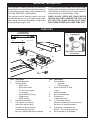
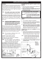
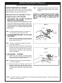
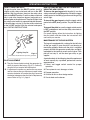
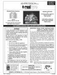
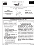
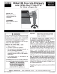
Owner’s
Manual
AUTOMATIC REMOTE LIGHTING SAFETY PILOT SYSTEM
FOR NATURAL OR PROPANE GAS
& FOR USE WITH PETERSON GAS LOG SETS ONLY
FEATURES
• SWITCH OPERATED ON/OFF •
• OPTIONAL REMOTE READY •
Installer: Leave this
manual with the consumer.
SUITABLE FOR THE FOLLOWING BURNERS:
• PAN BURNERS (P-SERIES) •
• G4 SERIES BURNERS •
• G45 SERIES BURNERS •
Consumer: Retain this
manual for future reference.
90,000 BTU CAPACITY
Model APK-11(M)(P)
FOR USE WITH PETERSON GAS LOG SETS ONLY
WARNING
Important: Read these instructions carefully
before starting installation.
If the information in this manual is not followed
exactly, a fire or explosion may result, causing
property damage, personal injury, or loss of life.
- Do not store or use gasoline or other
flammable vapors and liquids in the vicinity
of this or any other appliance.
WHAT TO DO IF YOU SMELL GAS:
• Open a window.
• Do not try to light any appliance.
• Do not touch any electrical switch; do not use
any phone in the building.
• Immediately call the gas supplier from a
neighbor’s phone. Follow the gas supplier’s
instructions.
• If you cannot reach the gas supplier, call the
fire department.
- Installation and service must be
performed by a qualified installer,
service agency, or the gas supplier.
INSTALLER & CONSUMER
These instructions MUST be
retained with this appliance
BE SURE DAMPER IS FULLY OPEN
WHEN OPERATING THE LOG SET
PETERSON VENTED GAS LOG SETS ARE TO
BE OPERATED ONLY IN A FULLY VENTED,
NONCOMBUSTIBLE FIREPLACE WITH DAMPER
AND CHIMNEY FREE OF ANY OBSTRUCTIONS. THE
FIREPLACE MUST BE DESIGNED AND APPROVED
TO BURN WOOD. Like burning natural firewood, the
Peterson log set is designed to burn with a yellow,
smoky flame. For this reason, it must be adequately
vented. Be sure the fireplace damper is fully open when
you burn the gas log set. The smallest dimension of the
chimney flue must be at least 8". If it is smaller, DO NOT
USE A PETERSON LOG SET. If fumes from the burner
emerge into the room when the damper is fully open,
creating a smell like a smoldering oil lamp, it indicates
that the fireplace draft is defective. Check chimney flue
for obstructions. DO NOT OPERATE LOGS UNTIL THE
FIREPLACE DRAFT IS CORRECTED. Check with your
dealer or installer. Do not use firewood with this unit.
This safety pilot system contains a control certified
by C.S.A.
Robert H. Peterson Co. • 14724 East Proctor Avenue • City of Industry, California 91746
REV 2-0907161326
1
No. L-A2-01909
TABLE OF CONTENTS
PARTS LIST
IMPORTANT INFORMATION
INSTALLATION INSTRUCTIONS
SAFETY VALVE INSTALLATION
MOUNTING THE PILOT ASSEMBLY TO THE PETERSON REAL-FYRE® BURNER
OPERATING INSTRUCTIONS
TROUBLESHOOTING
WARRANTY
2
3
3
4
4
5
6
7
8
IMPORTANT INFORMATION
The installation, including provisions for combustion
and ventilation air, must conform with local codes or,
in the absence of local codes, with the National Fuel
Gas Code, ANSI Z223.1 (latest edition).
This appliance must be isolated from the gas supply
piping system by closing its individual manual shutoff
valve during any testing of the gas supply system at
test pressures up to and including 1/2 psig.
This appliance and its individual shutoff valve must
be disconnected from the gas supply piping system
when testing at pressures exceeding 1/2 psig. Do this
by closing the gas supply valve.
WHEN GLASS FIREPLACE ENCLOSURES
(DOORS) ARE USED, OPERATE THE GAS LOG
SET WITH THE GLASS DOORS FULLY OPEN;
BOTH SIDES IF FIREPLACE IS SEE-THRU TYPE.
PARTS LIST
CK-4 CONNECTOR KIT
SUPPLIED WITH BURNER
HEARTH
Hearth
ELBOW
elbow
12
(If equipped)
CK-4
TUBE
CK-4 CONNECTOR
Connector tube
9
SMALL
BRASS
Small brass
connector
CONNECTOR
(do not
(DOuse)
NOT USE)
6
5
1
Remote kit with remote
instructions.
8
7
6
Generator
spade clips
Pilot gas
supply
3
4
Street
elbow
2
Brass
elbow
11
(14 D.S.)
Item Description
1.
Radiant heatshield
2.
Valve assembly
• Safety valve
• Brass elbow (flare)
• 3/8" NPT close nipple
• 3/8" coupling
• Street elbow 3/8 (3 req.)
• Toggle switch
• Switch bracket
3.
Flame diverter bracket
Fuel injector (for use with
4.
natural gas log sets only)
Air mixer not shown (for use
with propane gas log sets)
Item 4 is supplied with burner assembly
Item Description
5.
Pilot assembly
• Generator
• Pilot gas supply
6.
Screw #10 x 3/8 PH, BLK
(4 req.)
7.
Mounting bracket
8.
Burner insulation pad
9.
Connector kit
(supplied w/burner)
1/4" slotted bolt and nut
10.
(For front flame burner installation only.
Not shown in illustration above.)
11.
Fuel injector (enlarged for use
with 24" - 30" natural gas log sets)
12.
RR-1A remote kit (if equipped)
3
INSTALLATION INSTRUCTIONS
(Refer to the PARTS LIST when following these instructions.)
CONNECTING THE SAFETY VALVE TO THE
Be sure the automatic remote lighting safety pilot system has BURNER
GENERAL
been assembled for the proper gas. Systems labeled APK11(M) are for natural gas and APK-11(M)P are for propane
gas. APK-11(M) is for use only with Peterson natural gas
burner systems sizes 12" to 30". Larger burner systems
should use the APK-10(M).
1. Follow the instructions supplied with the Peterson gas
log set for proper burner placement.
2. Attach the street elbow (see PARTS LIST) to the fuel
injector or air mixer (Item 4) supplied with burner. Ensure
all connections are tight.
INSTALLATION ON SEE THRU BURNER
Note: APK-11(M)P can be used on all standard
size propane burner systems to 30" and on
see-thru propane burner systems up to 18".
Connect the street elbow to the “tee” fitting on the burner
manifold. Ensure all connection are tight.
Important: For safe and correct operation, attach
pilot assembly to the burner pan that
receives gas first during operation
(see Fig. 3-1).
A fuel injector (for natural gas) is included with the unit
which contains an enlarged orifice (14 D.S.). If you are using
a 24" or 30" natural gas log set, remove the fuel injector
from the burner pan and replace it with the enlarged fuel
injector. There is no need to replace the air mixer if using
propane gas.
CONNECTING THE SAFETY VALVE TO THE GAS
SUPPLY
1. Turn off the gas supply to the fireplace.
2. Attach the hearth elbow supplied with the CK-4
connector kit (Item 9) to the gas supply. This item
is supplied with the burner assembly.
3. Remove and discard the small brass connector
elbow from the CK-4. Attach the CK-4 connector
tube, one end to the hearth elbow that is attached
to the gas supply and the other end to the brass
elbow that is attached to the safety valve.
Note: If the flame height is adequate, there is no
need to use the enlarged orifice (14 D.S.)
provided with this kit. Be sure all cautions
and warnings contained in the Peterson
gas log instructions are followed.
These instructions must be used as a supplement to the
instructions supplied with the gas log set. Follow the gas log
set instructions and make adjustments as appropriate for the
addition of the unit. Gas supply must be 1/2" minimum I.D.
and with proper pressures. Use Teflon tape or pipe sealing
compound that is resistant to propane gas on all male pipe
connections. Make sure that all connections are tight.
CONNECTING THE PILOT ASSEMBLY TO THE
SAFETY VALVE
1. Connect one of the spade clips on the wires from the
generator (Item 5) to the terminal screw marked TP and
the other spade clip to the terminal screw marked THTP on the safety pilot valve (Item 2). Tighten screws.
Note: This unit adds six additional inches to the
footprint of the burner system.
Note:
SAFETY VALVE INSTALLATION
Use Teflon tape or pipe compound for all male pipe
connections to prevent gas leaks.
Two wires, one from the toggle switch control and
one from the generator, should be connected to
terminal screw marked TH-TP. BE SURE THE
JUMPER WIRE IS IN PLACE (Fig. 3-1).
2. Screw the pilot gas supply (Item 5) to the safety valve
at the pilot gas port marked PILOT. Be sure the
connection is tight.
Note: The valve assembly is pre-assembled for
ease of installation. The valve must be
installed on the right side of the burner.
PLACEMENT OF THE APK SAFETY VALVE
Elbow
Burner pan
Correct placement of the APK safety valve in the fireplace
is important to ensure proper operation. The valve must be
placed in the front right corner of the fireplace. Placement in
the front left corner of the fireplace or outside the firebox is also
permitted, but may require additional connecting parts.
Fig. 4-2
See-thru
installation
schematic
Pilot assembly
Direction of
gas flow
Attach pilot
assembly here
APK-11
valve
heatshield
This burner pan
will receive gas
first
Flame divertor
bracket
WIRING
DIAGRAM
Street
elbow
Nipple
Brass
elbow
Fig. 4-1
4
To CK
connector kit
Gas flow
to valve
INSTALLATION INSTRUCTIONS (cont.)
(Refer to the PARTS LIST when following these instructions)
Note: The generator and gas supply leads should
not be touching the burner pan or be placed
in the fire.
RADIANT HEATSHIELD PLACEMENT
Cover the safety valve (Item 2) with the radiant
heatshield (Item 1). Be sure the solid black face of the
shield is between the valve and the burner.
CHECK ALL CONNECTIONS FOR GAS LEAKS
USING A SOAPY WATER SOLUTION. NEVER
USE AN OPEN FLAME TO CHECK FOR GAS
CK-4 Connector tube
LEAKS.
Hearth
MOUNTING THE PILOT ASSEMBLY TO THE
PETERSON REAL-FYRE® BURNER
1. ATTACHING THE FLAME DIVERTER
BRACKET ON THE BURNER
Attach the flame diverter bracket (Item 3) to the
side wall of the burner pan nearest to the valve.
The flame diverter bracket should be placed
approximately 1 1/4" from the back side of the
burner pan.
elbow
Fig. 5-1
Pilot
assembly
Note: The flame diverter bracket is used only on
G4, GX4, VG4, and P series burners.
Mounting
bracket
2. GLOWING EMBER BURNER - G4, GX4, AND
VG4 SERIES
Insulation
pad
a. Attach the pilot assembly mounting bracket
(Item 7) to the pilot assembly (Item 5) with #10
screws (Item 6) (Fig. 4-1).
Burner
pan
Flame
diverter
bracket
Note: Bracket, insulation pad and pilot assembly
are shown attached.
b. Place the burner insulation pad (Item 8)
between the bracket and the burner. Insert the
screws (Item 6) through the pilot assembly,
insulation pad, and holes in the side of the
burner, and tighten.
Fig. 5-2
Pilot
assembly
3. PAN BURNER — P SERIES
Flame diverter
bracket
a. Attach the pilot assembly mounting bracket
(Item 7) to the pilot assembly (Item 5) with #10
screws (Item 6), as shown in Fig. 4-2.
Note: Bracket, insulation pad, and pilot assembly
are shown attached.
Burner
pan
Mounting
bracket
Insulation
pad
b. Place the burner insulation pad (Item 8)
between the bracket and the burner. Insert
the screws (Item 6) through the pilot assembly,
insulation pad, and holes in the side of the
burner.
Note: The APK-11(M)(P) is compatible with all Peterson remote control options. Contact your Peterson
dealer for more information.
5
OPERATING INSTRUCTIONS
HOW TO LIGHT THE PILOT
HOW TO TURN THE GAS LOG SET ON AND OFF
USING THE APK SYSTEM
To light the pilot from the PILOT position, push in
slightly on the safety valve knob and turn to the OFF
position. Wait five minutes, then turn the safety valve
knob to the PILOT position. Push the safety valve knob
fully in and at the same time place a long match or a
butane lighter at the pilot burner. The pilot will light. Hold
the safety valve knob in for approximately 60 seconds.
If the pilot does not stay lit, turn the safety valve knob
to the full OFF position. Wait five minutes and repeat
the LIGHTING INSTRUCTIONS.
To turn on the gas log set with the pilot lit, turn the
safety valve knob to the ON position. Switch the toggle
switch control to the ON (up) position and the gas log
set will light.
To turn off the gas log set, switch the toggle switch
control to the OFF (down) position. The pilot will remain
lit.
To turn off the pilot, be sure the toggle switch control
is OFF, and depress and turn the safety valve knob to
the OFF position.
Generator
For remote lighting; follow the instructions for lighting
the pilot above and then follow the instructions that
came with your remote.
MAINTENANCE OF THE APK SYSTEM
The log set is equipped with a safety pilot that will shut
off the gas supply in case the pilot is not burning or
functioning properly. Make sure the pilot is adjusted
properly and that the generator spade clips are tightly
connected to the terminal screws on the valve. If the
pilot will not stay lit, call the local gas utility or gas
supplier.
Pilot
Lighting the pilot
Fig. 6-1
Pilot flame should encircle top of the generator
A periodic check of the following should be performed
at least annually by a qualified, professional service
representative:
PILOT ADJUSTMENT
A. The pilot flame should encircle the generator tip,
which is preset at the factory (Fig. 2-1). Ordinarily,
the pilot will not require field adjustment.
1. Valves and toggle switch control for proper
operation.
2. Flue system for rust, damage, or leaks.
B. If adjustment is necessary, remove the cap screw
and turn the smaller gas adjustment screw inside
counter-clockwise to increase the pilot flame and
clockwise to decrease the pilot flame. Replace cap
screw. Refer to Fig. 3-1, page 3.
3. Damper operation.
4. Orifices for dirt or other foreign matter.
5. Visual check on the burner.
6
TROUBLESHOOTING
PROBLEM
CAUSE
SOLUTION
1. Pilot will not stay
lit
a. Pilot generator may not be
producing sufficient millivoltage
a. Check with a millivolt meter. Should be
250 millivolts or more
b. Pilot flame is making a blowing
noise
b. Pilot needs adjusting. See PILOT
ADJUSTMENT
c. Generator wire leads are attached
to the wrong terminals on the
valve
c. See CONNECTING PILOT ASSEMBLY
TO SAFETY VALVE
D. Replace valve
d. Defective thermomagnet safety in
the valve
2. Pilot burning - no
gas to burner
a. Safety valve not turned to the ON
position after lighting pilot.
b. Wire leads are not connected
to the proper valve terminals or
toggle switch terminals are not
tight
c. Pilot generator may not be
producing sufficient millivoltage
a. Turn to ON position.
b. Make sure all wire leads are tight and
attached to proper terminals (see
wiring diagram on page 3)
c. See section 1a above
d. Replace the valve
d. Defective valve
3. Log set not burning
properly
a. Low flame/uneven flame
a. Check for low gas pressure; should
have operating pressures of 7" w.c..
for natural gas, 11" w.c. for propane
at manifold
b. Burner should be filled completely with
sand or vermiculite (propane)
4. Log set operates
but will not shut
off
a. Toggle switch control lead wires
to the valve may be shorted
together or on wrong terminals
a. See page 3 (wiring diagram)
5. Fr e q u e n t p i l o t
outage
a. Pilot flame is out of adjustment
a. See section 1b above
b. Down drafts from the chimney
extinguishing the pilot
b. Check draft. Consult with a qualified
chimney expert
6. Log set shuts down
during operation
a. Glass doors closed causing
excessive heat buildup
a. Open glass doors
b. P i l o t g e n e ra t o r i m p r o p e r l y
mounted on rear of the burner
pans
c. Heatshield not in place
7
b. See MOUNTING PILOT ASSEMBLY
TO REAL-FRYE® BURNERS
c. Place heatshield over the valve. Be
sure the solid black face of the shield
is between the valve and the burner
WARRANTY
PETERSON VENTED GAS LOG SETS
LIMITED WARRANTY
All Peterson gas logs are WARRANTED for as long as you own them (lifetime).
All Peterson burner assemblies are WARRANTED for TEN (10) YEARS.
SPK-26 controls are covered by a THREE (3) YEAR “All Parts” Warranty.
All other Peterson valves, pilots, and controls are covered by a ONE (1) YEAR Limited Warranty (excluding batteries).
PLEASE KEEP A COPY OF YOUR SALES SLIP FOR PROOF OF PURCHASE
This warranty applies to the original purchaser and to single family residential use only. It commences from date of purchase, and is valid only with
proof of purchase.
This warranty does not cover parts becoming defective through misuse, accidental damage, electrical damage, improper handling, storage, and/or
installation. Product must be installed (and gas must be connected) as specified in the instructions or operator’s manual, by a qualified professional
installer. Accessories, parts, valves, remotes, etc., when used must be Peterson Co. product.
This warranty does not apply to rust, corrosion, oxidation, or discoloration, unless the affected component becomes inoperable. It does not cover
labor or labor-related charges.
This warranty specifically excludes liability for indirect, incidental, or consequential damages. Some states do not allow the exclusion or limitation of
incidental or consequential damages, so the above exclusion may not apply to you. This warranty gives you specified legal rights, and you may have
other rights that may vary from state to state.
For additional information regarding this warranty, or to place a warranty claim, contact the R.H. Peterson dealer where the product was purchased.
TO REGISTER YOUR PRODUCT ONLINE GO TO: WWW.RHPETERSON.COM,
AND CLICK ON PRODUCT REGISTRATION. THANK YOU FOR YOUR PURCHASE.
ROBERT H. PETERSON CO.
Quality Check
Date:___________
Orifice # (Main):__________
Orifice # (Other):__________
Leak Test:
___________
Burn Test:
___________
Gas Type:
NAT. / PROPANE
Model #:
___________
Serial #:
___________
Air Shutter: ___________
Inspector: ___________
Robert H. Peterson Co. • 14724 East Proctor Avenue • City of Industry, CA 91746
8