1
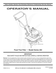
Safety ,, Set-Up ,, Operation ,, Adjustments ,, Maintenance ,, Troubleshooting ,, Parts Lists ,, Warranty
A
OF
A
O
ingle-Sta!e
now
Thrower
AL
Model
Model
Model
Model
Model
230,
240,
250,
260,
261,
$230
S240
S250
S260
S261
iMPORTANT
READ SAFETY
RULES AND iNSTRUCTiONS
CAREFULLY
BEFORE
OPERATION
Warning: This unit is equippedwith an internalcombustionengineand shouldnot be usedon or nearany unimprovedforest-covered,brushcoveredor grass-coveredland unlesstheengine'sexhaustsystemis equippedwith a sparkarrestermeetingapplicablelocalor statelaws(if any).
If a sparkarresteris used,it shouldbe maintainedin effectiveworkingorder by the operator.In theState of Californiathe aboveis requiredbylaw
(Section4442 of the CaliforniaPublicResourcesCode). Otherstatesmay havesimilarlaws.Federallaws applyon federallands.A sparkarrester
for the muffleris availablethroughyour nearestengineauthorizedservicedealeror contactthe servicedepartment,RO. Box361131Cleveland,
Ohio 44136-0019.
PRINTEDIN U.S.A.
For USCustomers: MTDLLC,P.O.BOX361131CLEVELAND,OHiO44136-0019
FORMNO. 769-00805C
For CanadianCustomers: MTDProducts Ltd., P.O.BOX 1386,KiTCHENER,ONTARION2G4J1
05/17/06
This Operator's Manual is an important part of your new snow thrower, it will help you assemble,
prepare and maintain the unit for best performance.
Please read and understand what it says.
Table of Contents
Safety Labels ......................................................
Safe Operation Practices ...................................
Set Up & Adjustment ..........................................
Know Your Snow Thrower ..................................
3
4
6
7
Adjustments
& Maintenance
...........................
Off-Season Storage ..........................................
Trouble Shooting ..............................................
illustrated Parts Lists .......................................
10
12
13
14
Operation
8
Warranty ............................................................
18
.............................................................
Finding and Recording Model Number
BEFOREYOU START ASSEMBLING
YOUR NEW EQUIPMENT,
please locate the model plate on the equipment and copy the
the model number and the serial number to the sample model
plate provided to the right. You can locate the model plate by
standing at the operating position and looking down at the
frame.
Model
Num#ro
Number
de
module
XXXXXXXXXXX
Serial
Number
Num#ro
de
s#rier
XXXXXXXXXXX
MTD LLC
CLEVELAND, OH 44136
MTD PRODUCTS LIMITED
KITCHENER, ON N2G 4J1
USA-www.mtdproducts.com
CAN=www.mtdcanada.com
1-800=800-7310
1=800=668=1238
Customer Support
Please do NOTreturn
the unit to the retailer from which it was purchased,
without first contacting Customer Support.
If you have difficulty assembling this product or have any questions regarding the controls, operation or maintenanceof this unit,
you can seek help from the experts. Choose from the options below:
1.Visit www.mtdcanada.cafor many useful suggestions, click on Customer Support button.
2. Call a CustomerSupport Representative:For US Customers: 1-330-220-4MTD (4683)or 1-800-800-7310
For Canadian Customers" 1-800-668-1238
3. The engine manufacturer is responsiblefor all enigne-related issues with regards to performance, power-rating,specifications, warranty and service. Please refer to the engine manufacturer's Owner's/Operator's Manual, packedseparately with
your unit, for more information.
Please have your unit's model number and serial number ready when you call. See previous section to locate this information.
You will be asked to enter the serial number in order to processyour call.
2
i i l_I ii_ _ i _iii _! i _
_ii_ ii
WARNING
• NEVERPUT HANDiN CHUTE.CAN
AMPUTATEHANDSAND FINGERS.
• STOPENGINEANDAUGERBEFOREUSING
CLEAN-OUT
TOOLORSTICK.
This symbol points
out importantsafety
instructionswhich, if
not followed,could
endangerthe personal
safety and/or property
of yourselfand others.
Read and followall
instructionsin this
manual beforeattemptingto operate
this machine. Failure
to complywith these
instructionsmay result
in personalinjury.When
you see this symbol.
HEED ITS WARNING!
Your Responsibility
Restrict the use
of this power machine
to persons who read,
understand
and follow the warnings
and instructions
in this manual
and onthe machine.
3
WARNING: Engine Exhaust, some of its constituents, and certain vehicle components contain or emit chemicals known to State of Californiato cause cancer and
birth defects or other reproductiveharm.
DANGER: This machine was built to be operated according to the rules for safe operation in this
manual. As with any type of power equipment, carelessness or error on the part of the operator can
result in serious injury. This machine is capable of amputating hands and feet and throwing objects.
Failureto observe the following safety instructions
could result in serious injuryor death.
Training
WARNING
This symbol points
out importantsafety
instructionswhich, if not
followed,could endanger
the personalsafetyand/
i or propertyof yourself
and others. Readand
follow all instructions
in this manual before
Preparation
1. Read,understand,andfollowall instructionson the
machineandin the manual(s)beforeattemptingto
assembleand operate.Keepthis manualina safe place
forfutureand regularreferenceandfor ordering
replacementparts.
2. Be familiarwithall controlsandtheir properoperation.
Knowhowto stopthe machineanddisengagethem quickly.
3. Neverallowchildrenunder14 yearsoldto operatethis
machine.Children14 yearsold andovershouldread
andunderstandthe operationinstructionsandsafety
rulesin thismanualand shouldbe trainedand supervised
bya parent.
4. Neverallowadultsto operatethis machinewithout
properinstruction.
5. Thrownobjectscan causeserious personalinjury.Plan
yoursnow-throwingpatternto avoiddischargeof material
towardroads,bystandersandthe like.
6. Keepbystanders,helpers,pets andchildrenat least 75 feet
fromthe machinewhileit is in operation.Stopmachineif
anyoneentersthe area.
7. Exercisecautionto avoidslippingor falling,especially
when operatingin reverse.
attemptingto operate
this machine.Failure
to comply with these
instructionsmay result
in personalinjury.When
you see this symbol.
i HEED iTS WARNING!
1. Thoroughlyinspectthe area wherethe equipmentis to be
used. Removeall doormats,newspapers,sleds, boards,
wiresand otherforeignobjects,whichcould be tripped over
or thrown bythe auger/impeller.
2. Alwayswearsafetyglasses or eye shieldsduringoperation
andwhile performingan adjustmentor repairto protectyour
eyes. Thrownobjectswhich ricochetcan cause serious
injury to the eyes.
3. Do not operatewithoutwearingadequatewinterouter
garments.Do not wearjewelry, long scarvesor other
loose clothing,whichcould becomeentangledin moving
parts. Wearfootwearwhich will improvefooting on
slipperysurfaces.
4. Usea groundedthree-wireextensioncordand receptacle
forall units withelectric startengines.
5. Adjustcollectorhousingheight to cleargravel or crushed
rock surfaces.
6. Disengageall control leversbeforestartingthe engine.
7. Neverattemptto makeany adjustmentswhileengineis
running,exceptwherespecificallyrecommendedinthe
operator'smanual.
8,
Let engine andmachineadjustto outdoortemperature
beforestartingto clearsnow.
9. Toavoid personalinjury or propertydamage use
extremecare in handlinggasoline.Gasolineis extremely
flammableand the vapors are explosive.Serious personal
injury can occur when gasolineis spilledon yourselfor
yourclothes,which can ignite.Washyourskin andchange
clothesimmediately.
a. Useonly an approvedgasolinecontainer.
b. Extinguishall cigarettes,cigars, pipes andothersources
of ignition.
c. Neverfuel machineindoors.
d. Neverremovegas cap or add fuel whilethe engineis
hot or running.
e. Allow engineto coolat leasttwo minutesbefore
refueling.
f. Neveroverfill fuel tank. Filltank to no morethan
Your Responsibility
i
Restrictthe use of
this power machine
i to personswho read,
understand and follow
Y2inch below bottomoffiller neckto providespace
for fuel expansion.
g. Replacegasolinecap andtighten securely.
h. If gasolineis spilled,wipe it off the engine and
equipment.Movemachineto anotherarea.Wait 5
minutesbeforestartingthe engine.
i. Neverstorethe machineor fuel containerinside where
the warnings and
instructions in this
manual and on
the machine.
there is an openflame, sparkor pilot light (e.g.furnace,
waterheater,spaceheater,clothesdryeretc.).
j. Allow machineto cool at least5 minutesbeforestoring.
4
Operation
Maintenance
1. Do not put handsor feet near rotatingparts, inthe
auger/impellerhousingor chute assembly.Contactwiththe
rotating partscan amputatehandsand feet.
2. The auger/impellercontrol leveris a safetydevice.Never
bypassits operation.Doing so makesthe machineunsafe
and may causepersonalinjury.
3. The control leversmustoperateeasily in bothdirections
and automaticallyreturnto the disengagedpositionwhen
released.
& Storage
1. Nevertamper withsafetydevices.Checktheir proper
operationregularly.Referto the maintenanceand
adjustmentsectionsof this manual.
2. Beforecleaning,repairing,or inspectingmachine
disengageall control leversandstop the engine.Wait until
the auger/impellercome to a completestop.Disconnectthe
sparkplug wire and groundagainstthe engineto prevent
unintendedstarting.
3. Checkbolts and screwsfor propertightness at frequent
intervalsto keepthe machinein safe workingcondition.
Also,visuallyinspectmachinefor any damage.
4. Do not changethe engine governorsettingor over-speed
the engine.The governorcontrols the maximumsafe
operatingspeed of the engine.
5. Snowthrowershaveplatesand skidshoesare subjectto
wearanddamage. For yoursafetyprotection,frequently
check all componentsand replacewith originalequipment
manufacturer's(OEM) parts only."Use of partswhich do
not meetthe original equipmentspecificationsmaylead to
improperperformanceandcompromisesafety!"
6. Checkcontrols periodicallyto verify they engageand
disengageproperlyandadjust, if necessary.Referto the
adjustmentsection inthis operator'smanualfor instructions.
7. Maintainor replacesafetyandinstructionlabels,as
necessary.
8. Observeproper disposallaws andregulationsfor gas, oil,
etc. to protectthe environment.
9. Priorto storing,run machinea few minutesto clearsnow
from machineand preventfreezeup of auger/impeller.
10. Neverstorethe machineor fuel containerinside where
thereis an openflame, sparkor pilot lightsuch as a water
heater,furnace, clothesdryeretc.
11. Alwaysreferto the operator'smanualfor proper instructions
on off-seasonstorage.
4. Neveroperatewith a missing or damagedchuteassembly.
Keep all safetydevices in place andworking.
5. Neverrun an engine indoorsor ina poorly ventilatedarea.
Engineexhaustcontainscarbonmonoxide,an odorlessand
deadlygas.
6. Do not operate machinewhileunderthe influenceof alcohol
or drugs.
7. Mufflerand engine becomehot andcan causea burn.Do
not touch.
8. Exerciseextremecaution when operatingon or crossing
gravel surfaces.Stay alert for hidden hazardsor traffic.
9. Exercisecautionwhen changingdirectionandwhile
operatingon slopes.
10. Planyour snow-throwingpatternto avoiddischargetowards
windows,walls, cars etc. Thus, avoidingpossibleproperty
damageor personalinjury caused bya ricochet.
11.Neverdirectdischargeat children,bystandersandpets or
allowanyoneinfront of the machine.
12.Do not overloadmachinecapacityby attemptingto clear
snow at too fast of a rate.
13.Neveroperatethis machinewithoutgood visibility or light.
Alwaysbe sure of yourfooting and keepa firmhold on the
handles.Walk, neverrun.
14.Disengagepowerto the auger/impellerwhen transporting
or not inuse.
Do not modify
15.Neveroperate machineat high transportspeeds on slippery
surfaces.Lookdown and behindand use carewhen
engine
Toavoid seriousinjury or death,do not modifyengine inany
backing up.
way.Tamperingwiththe governorsettingcan leadto a runaway
16. Ifthe machineshould startto vibrate abnormally,stop the
engineandcauseit to operateat unsafespeeds.Nevertamper
engine,disconnectthe spark plug wire andground it against withfactorysettingof enginegovernor.
the engine.Inspectthoroughlyfor damage.Repairany
Notice regarding
Emissions
damage beforestartingandoperating.
Engineswhichare certifiedto complywithCaliforniaandfederal
17.Disengageall control leversand stop engine beforeyou
EPAemissionregulationsfor SORE(SmallOff RoadEquipment)
leave the operatingposition(behindthe handles).Wait
arecertified to operateon regularunleadedgasoline,and
until the auger/impellercomesto a completestop before
may includethe followingemissioncontrolsystems:Engine
uncloggingthe chute assembly,makingany adjustments,or Modification(EM)andThreeWayCatalyst(TWO)if so equipped.
inspections.
Your Responsibility
18.Neverput yourhand inthe dischargeor collector openings.
Restrictthe useof this powermachineto personswho read,
Alwaysuse the clean-outtool providedto unclogthe
understandandfollowthe warningsandinstructionsinthis
dischargeopening.Do not unclogchute assemblywhile
manualandon the machine.
engine is running.Shutoff engine and remainbehind
handles until all movingparts havestoppedbefore
unclogging.
19.Use onlyattachmentsand accessoriesapprovedbythe
manufacturer(e.g.wheel weights,tire chains,cabs etc.).
20. Ifsituationsoccur whichare not coveredinthis manual,
use care and goodjudgment.Contactyour dealeror call
(800) 800-7310for assistanceandthe name of your nearest
servicingdealer..
5
WARNING
This symbol points
out importantsafety
instructionswhich, if not
followed,could endanger
the personalsafety and/
or propertyof yourself
and others. Read and
follow all instructions
in this manualbefore
attemptingto operate
this machine.Failure
to comply with these
instructionsmay result
in personal injury.When
you seethis symbol.
HEED iTS WARNING!
Your Responsibility
Restrict the use of
this power machine
to personswho read,
understandand follow
the warnings and
instructions in this
manual and on
the machine.
Contents
of Carton
Cartoncontentsare listedbelowwith part numbersin
parentheses,
1. TwoignitionKeys(725-0201)
2, 2,6 oz Bottleof 2 CycleOil (737-04037)
3, ExtensionCord(if soequipped)(629-0236)
__IL
wire and groundit against the engineto
ARNING: Disconnectthe spark plug
preventunintended starting.
Positioning
the Upper Handle
1. Removepackingmaterial,if present.
2. Makingsurenot to pinchthe cablein the process,
pivotthe upper handleintothe operatingpositionas
illustratedin Figure1 untilit clicksinto place.
3. Tightenthe star knobsto securethe handlein place
as in Figure1.
Figure 1
NOTE: This Operator's
Manual covers several
models. Snow thrower
Assembling the Discharge
/
Chute
For shippingreasons,the snow throwerhasbeen
packagedwith the upperchute pivotedall the waydown.
Topivot itupward,proceedas follows:
features vary by
model. Not all features
discussed in this
,
manual are applicable
to all snow thrower
models.
,
NOTE: All references
Turnthe chute untilthe chuteopeningis facing
straightahead. Removethewing knob,flat washer
and carriagebolt fromthe lowerchute. See Figure2.
Pivotthe upperchute upwardoverthe lip on the lower
chuteso that there is NOgap betweenthe upper
chuteand the lowerchute.
3. Resecurewith the hardwarejust removed. If installed
correctly,your snowthrowershouldlook like Figure3.
i to left or right side of
the snow thrower is
IMPORTANT:Do not usethe chute handleto lift the
snowthrower.
i from the operating
position only.
Figure 2
IMPORTANT:
Do not usethe chute
handle to lift the snow
thrower.
Figure 3
6
AugerControlHandle_
ElectricStarter Button
(if equipped)
Figure4A
YourSnOw
FuelCap
Primer
Spark PlugAccess
ChuteAssembl
IMPORTANT:
This unit runs on a
mixture of gasoline
and oil. Do NOT
/
ShavePlate
operate the snow
thrower without first
/
Auger
reading !,heengines
operator s manual for
instructions regarding proper fuel and
engine oil.
Figure 4
IMPORTANT:This unit runson a mixtureof gasoline
and oil. DoNOToperatethe snowthrowerwithoutfirst
readingthe enginesoperator'smanualfor instructions
regardingproperfueland engine oil.
Spark
Plug Cover
Removesparkplug coverto access sparkplug.
Auger
Whenengaged,the augersrotationdrawssnowinto the
augerhousingand throwsitout the dischargechute.
Activatingchoke controlclosesthechoke plateon
Rubberpaddleson the augersalso aid in propellingthe
carburetorand aids in startingengine.Referto the engine unitas they come in contactwith the pavement.
manualpackedwith unitfor moredetailedinstructions.
Choke
Lever
Auger Control
Primer
Handle
Depressingprimerforcesfueldirectlyinto engine's
carburetorto aid in cold-weatherstarting.Referto engine
manualpackedwith unitfor moredetailedinstructions.
Locatedon theupperhandle,theaugercontrolhandle
is usedto engageand disengagedriveto theauger.
Squeezethecontrolhandleagainstthe upperhandleto
engageauger;releaseit todisengage.
Ignition
Discharge
Key
Ignitionkeymust be present,insertedin keyswitch,and
in the "ON" positionfor engineto start.
Recoil
Chute / Chute
Handle
Rotatethe dischargechuteto theleft or rightusingchute
handle.Pitchof the dischargechutecontrolsangleat
whichthesnowis thrown.Loosenwingknobon side
of thedischargechutebeforepivotingdischargechute
upwardor downward.Retightenthe knoboncedesired
positionhasbeenachieved.
Starter
The starterhandleis usedto manuallystartthe engine.
Electric
Starter Button (If so equipped)
Pressingthe electric starterbutton engagesthe
engine'selectric starterwhen plugged intoa 120V
power souroe
Shave
Plate
Theshaveplatemaintainscontactwithpavementas
thesnowthroweris propelled,allowingsnowcloseto
pavement'ssurfaceto bedischarged.
Electric
Starter Plug (If so equipped)
Requiresuseof a two-prongoutdoorextensioncord
(packedwith the snowthrower)and a 120Vpower
source/walloutlet.
7
I
Before Starti ng
Electric
_
WARNING:Before startingthe
_
WARNING:The electric starter must
engine,read,
understand,
andon
follow
all
instructionsand
warnings
the
machine and in this manual,
ALL
be
used withreceptacle
a properly at
grounded
three-prong
all times to
avoid the possibilityof electric shock.
1. Thespark plug wirewas disconnectedfor safety.
Attachsparkplug wireto sparkplug beforestarting,
i
Follow all instructionscarefully prior to
operatingthe electric starter.
IMPORTANT:Forcompleteand detailedengine
starting,stoppingand storinginstructions,it is recommendedthat you readthe enginemanualalsoincluded
with this unit.
i
1. Theelectricstarteris equippedwith a groundedthreewirepowercordand plug,and is designedto operate
on 120volt AC householdcurrent.
2. Determinethat your housewiringis a three-wire
Fuel And Oil Mixture
WARNING
Read, understand,
and follow all instructions and warnings
on the machine and
in this manual before
operating,
Use extreme care
when handling
gasoline. Gasoline is
extremely flammable
and the vapors are
explosive. Never fuel
the machine indoors
i or while the engine
is hot or running,
i Extinguish cigarettes,
i cigars, pipes and
other sources of
ignition.
i The electric starter
must be used with a
' properly grounded
three-prong receptacle at all times to
_
groundedsystem.Ask a licensedelectricianif you are
not certain.
handling gasoline. Gasoline is
WARNING:Use
extremecare
when
extremelyflammable
and the vapors
are explosive.Never fuel machine
indoorsor while the engineis hot or
running.Extinguish cigarettes, cigars,
pipesand other sourcesof ignition,
3. If your home wiring system is not a three-wire
grounded system, do not usethis electricstarter
underany conditions.
4. If your home electricalsystem is grounded, but
a three-holereceptacleis not available,one should
be installedby a licensedelectricianbeforeusingthe
IMPORTANT:This unitrunson a mixtureof gasoline
and oil. Do NOToperatethe snow throwerwithout
electricstarter.
5. If you have a grounded three-prong receptacle,
first readingthe enginesoperator'smanualfordetailed
proceedas follows.
instructionsregardingproperfueland engineoil.
Do NOToperatethe snow throwerwithoutthe fuelcap
securelyin placeon the fuel tank.
6. MoveChokeControlto the "Full"position.
7. PushPrimerthree (3) times, makingsureto cover
vent holewhen pushing.
8. Connectpowercord to switch boxon dash panel.
Plugthe otherend of powercord intoa three-prong
120-volt,grounded,AC receptacle.
Positioni ng the Discharge
Chute
1. Loosenthe star
knobfoundon
the left side of the
dischargechute
and pivotthe upper chute upward
9. Pushstarterbuttonto crank engine.
10.Whenenginestarts,releasestarterbutton,and move
chokegraduallyto 1/2Chokeuntil theengine runs
smoothly. NextmoveChoketo OFF.If enginefalters,
movechokeimmediately
to FULLand then gradually
to 1/2 thento OFE
ordownwardto
the
desiredpitch,
Retightenthe
star knobbefore
operatingthe snow
thrower.
11.Disconnectthe powercord.Always unplug from the
outlet first, and then from the snow thrower.
Figure 5
Recoil Starter
2. Rotatethe dischargechute to the left or rightusing
the chutehandle.See Figure5.
1. Movechokeleverto FULLchokeposition(cold engine
start).
TO Start Engine
2. If engineiswarm,placechokein OFF positioninstead
of FULL.
1. Insertignitionkey intoslot.
3. PushPrimerthree (3) times, makingsureto cover
2. Nowfollow the instructions
belowas itpertainsto
yourunit. See Figure5 for locationof controls.
vent holewhen pushing.
4. If engineiswarm,pushprimerbuttononlyonce.
avoid the possibility
of electric shock. Fol-
NOTE:Alwayscover venthole in primerbuttonwhen
pushing.Additionalprimingmaybe necessaryfor first
start iftemperatureisbelow15 degreesFahrenheit.
low all instructions
i carefully
Starter(if equipped)
prior to
5. Graspstarterhandleand pull rope out slowly,until it
pullsslightlyharder.Let rope rewindslowly.
operating the electric
starter,
6. Pull starterhandlerapidly.Do notallowhandleto snap
back.Allowitto rewindslowlywhilekeepinga firm
hold on the starterhandle.
8
7. As enginewarmsup and beginsto operateevenly,
rotatechoke leverslowlyto the 1/2 Chokeposition.
Whenthe enginebeginsto run smoothly,movethe
choketo the OFFposition.If enginefalters, return
to FULLchoke,then slowlymove to 1/2 thenOFF
position.
Operating
The pitchof the chute assemblycontrolsthe angleat
whichthe snow isthrown.
1. Loosenthe star knobfoundon the left sideof the
chuteassemblyand
pivotthe upper chute
upwardor downward
to the desiredpitch.
Retightenthe star
knobbeforeoperating
the snowthrower.
To Stop Engine
1. To stopengine,turnignitionkey counter-clockwise.
Disconnectthe sparkplug wirefrom the spark plug
to preventaccidentalstartingwhile equipmentis
unattended.
.
To help preventpossiblefreeze-up of starter,
proceedas follows:
1. Runenginefor a few minutesbeforestoppingto help
dry off anymoistureon the engine.
Clearing Snow
_
thrower with bystandersin front of or
ARNING:Neveroperatethe snow
near the dischargechute opening.
1. Engagethe auger by squeezingthe augercontrol
handleagainstthe upperhandle.See Figure5.
RecoilStarter:With engine running,pull starterrope
with a rapid,continuousfull arm strokethree or four
times. Pullingthe starterropewill producea loud
clatteringsound,which isnot harmfulto theengine or
starter.
2. Lift up slightlyon the handleto allowthe rubber
paddleson the auger to contactthe pavementand
propelthe snowthrowerforward.Pushingdownward
on the handlewill raisethe augersoff the ground
and stop forwardmotion.
4. Wipeall snowand moisturefrom the carburetorcover
in the areaof thecontrol levers.Also, movecontrol
leversbackand forth severaltimes. Leavechoke
control inthe FULLchoke position.
Opera
tm
ion
Positionthe chute
assemblyopening
Figure 6
by usingthe Chute
Handleto throw the snowin the desireddirection.
See inset Figure6.
2. ElectricStarter:Connectpowercord to switchbox
on engine,thento 120volt AC receptacle.With the
engine running,pushstarterbuttonand spin the
starterfor severalseconds.The unusualsoundmade
by spinningthe starterwill not harmengine or starter.
Disconnectthe powercord from receptaclefirst, and
then from switchbox.
.
the Snow Thrower
3. Dischargesnowdownwindwheneverpossible.
Slightlyoverlapeachpreviouslyclearedpath.
WARNING
Muffler'
engine
and
surroundingareas
become hot
can cause a burn,
Do not touch;
Never operate the
snow thrower with
bystanders in front of
or near the discharge
NOTE:Excessiveupwardpressureon the handlewill
result in prematurewearon the rubberauger blades
whichwouldnot be coveredbywarranty.
5. Removeignitionkey and disconnectsparkplug wireto
preventaccidentalstarting.
Operating
Tips
1. Runthe enginefor a few minutesbeforestoppingto
help dry anymoistureon theengine.
2. Cleanthe snowthrowerthoroughlyafter each use.
__i=
surroundingareas becomehot and
ARNING:Muffler,
engineand
can
causea burn.Be
carefuland do
not touch when hot.
NOTE: Excessive
upward pressure on
the handle will result
in premature wear
on the rubber auger
blades which would
not be covered by
warranty.
9
Shave Plate
1. Tocheckthe adjustmentof the shaveplate,placethe
uniton a levelsurface.The wheels,shaveplateand
augersshouldall contact levelsurface.Notethat if the
shaveplateis adjustedtoo high,snowmay blowunder
the housing.If the shaveplatewearsout excessively,
or the unit doesnot self-propel,the shaveplatemay
be too lowand needsto be adjusted.
NOTE:On newunits or units with a newshaveplate
installed,the augersmay be slightlyoff theground.
2. Toadjust,tip the snowthrowerback sothat it rests
on the handle.Loosenthe lock nuts and boltswhich
securethe shaveplateto the housing.See Figure7.
Movethe shaveplateto desiredpositionand retighten
the nuts and bolts securely.
Replacing
Figure 7
WARNING
Disconnect the
2. Installnewshaveplate,making suretheheadsof the
carriagebolts are on the insideof the housing.
3. Adjustthe shaveplateaccordingto instructions
above.Tightenthe nuts securelybeforeoperatingthe
snowthrower.
NEVER attempt to
make any adjustments while
NOTE: Forinformationregardingthe priceand availability
of ShavePlateKit referto customersupporton page 2.
the engine is running, except where
specified in
the operator's
manual.
stop engine. Wait
untilall moving
parts have come to a
complete stop.
Theshaveplate is attachedto the bottomof theauger
housingand is subjectto wear.It shouldbe checked
periodically.Thereare two wearingedgesand the shave
platecan be reversed.Referto Figure7.
1. Removethecarriageboltsand hexlock nuts which
attachit to the snowthrowerhousing.
spark plug wire
and ground it against
the engine to prevent
unintended starting.
Before servicing,
repairing, or inspecting, disengage the
control bail and
Shave Plate
Control Cable
As a resultof both thecontrolcable and thedrive belt
stretchingdue to wear,periodicadjustmentsmaybe
necessary.
Figure 8
If the augerseemsto hesitatewhenrotatingwhilethe
enginemaintainsa constantspeed,an adjustmentis
necessary.Proceedas follows:
_
wire and groundit against the engine
ARNING:Disconnectthe sparkplug
to preventunintended starting.
Theupper hole in the control handleprovidesfor an
adjustmentin cabletension.Toadjust,disconnectthe
end of controlcablefrom the bottomhole in the control
__k
any adjustments while the engineis
ARNING:NEVERattempt
to makethe
running,
exceptwhere specifiedin
operator's manual.
handleand reinsertit inthe upper hole.Insertthe cable
from theoutsideas shownin Figure8. Testthe snow
throwerto seeif thereisa noticeabledifference.
Carburetor
,_
be made to the enginewhile the engine
WARNING:If
any
adjustments
need to
is running(e.g.
carburetor),
keep
clear of all moving parts.Be careful of
muffler, engine and other surrounding
heated surfaces.
1. Referto the separateengine manual,packedwith
yourunit, for carburetoradjustmentinformation.
10
Replacing
A
Belt
or inspecting,disengage the control
ARNING:Beforeservicing,repairing,
bail
and stop engine. Wait until all
moving parts have come to a complete
stop. Disconnect spark plug wire and
ground it against the engine to prevent
unintended starting.
Removethebeltcoverbyremovingfivehexscrews.See
Figure9. Thensimplypullthebeltoff bygraspingitfromthe
bottomoftheaugerpulleyandpullingoff. Onceyou remove
thebeltfromthepulleys,youcanpushdownonthe idler
pulleyto releasethebeltfromunderthebeltkeeper.
intenal
To replacethe beltfollow theseinstructionsand referto
Figure10:
1. Pushdownon the Idlerpulley.
Jo
remove,pullbelt off here
J
Figure 9
2. Putbelton top of the augerpulley,underbelt keeper.
WARNING
3. Threadbeltaroundengine pulley.
4. Pushbeltoverbottomof augerpulley.
Before servicing;
repairing, or inspecting,
disengagethe control
stopengine:
lall moving
Reinstallthe belt cover removedearlier.
Engine
1. Referto the separateenginemanualfor all engine
maintenanceprocedures.
2. Checkengineand snowthrowerfrequentlyfor loose
hardware,and tightenas needed.
parts
have
come
toa
complete stop: Discon'
nect spark plugwire
Lubrication
gioun i
Lubricatepivotpoints on the controlhandleand the
extensionspringat the end of the controlcable with a
light oil once everyseasonand beforestorageof the
snow throwerat the end of the season.
Replacing
prevent
unintendedstarting.
Auger Paddles
J
The snowthrowerauger'srubber paddlesare subjectto
wearand shouldbe replacedif any signsof excessive
wear is present.
Figure 10
f
iMPORTANT:Do NOTallowthe auger'srubberpaddles
to wearto the pointwhereportionsof the metal auger
itself cancome in contact with the pavement.Doingso
can result in seriousdamageto your snowthrower.
PORTANT:
DoNOT,ow
NOTE:For informationregardingthe priceand availability
of Auger Kit referto customersupporton page2.
auger!s
padd es
Tochangethe rubberpaddles,proceedas follows:
1. Removethe existingrubberpaddlesby unscrewingthe
self-tappingscrewswhich securethemtothe auger.
See Figure11.
to the point where
portions of the metal
auger itself can come
incontact with the
2. Securethe replacementrubberpaddlesto the auger
usingthe hardwareremovedearlier.
pavement: Doing SO
can result in serious
damage
toyour
snow
thrower,
Figure 11
11
Observethe following,whenpreparingyour snow
throwerfor off-seasonstorage:
• Drainfuel intoan approvedcontaineroutdoors,away
from anyopen flame.Allowengine to cool. Extinguishcigarettes,cigars,pipesand other sources
of ignitionpriorto drainingfuel. Fuelleft in engine
duringwarmweatherdeterioratesand willcause
seriousstartingproblems.
If unitis to be storedover30 days,preparefor
storageas instructedin the separateenginemanual
packedwithyour unit.
Runengine untilfueltank is emptyand enginestops
due to lack of fuel.
Removegasolinefromcarburetorand fuel tank to
preventgum depositsfrom formingon these parts
and causingpossiblemalfunctionof engine.
WARNING
Never store snow
i thrower with fuel
in tank indoors or
in poorly ventilated
areas, where fuel
fumes may reach an
open flame, spark
or pilot light as on a
furnace, water heater,
i clothes dryer or gas
, appliance.
Drain fuel into an
Draincarburetorby pressingupwardon bowldrain,
locatedbelowthecarburetorcover.
• Fuelstabilizers,such as STA-BIL®,are an acceptable alternativein minimizingthe formationof fuel
gumdepositsduring storage.Do notdrain carburetor
if usinga fuel stabilizer.
• Wipeequipmentwith an oiled ragto preventrust.
• Removesparkplug and pour one ounceof engine
oil throughsparkplug hole into cylinder.Coverspark
plug hole with rag.Crankengine severaltimesto
distributeoil. Replacespark plug.
• Followthe lubricationrecommendationsfoundin the
MaintenanceSection.
Alwaysstorethe snowthrowerin a clean,dry area.
approved container
outdoors, away from
any open flame. Be
certain engine is
i cool. Do not smoke.
Fuel left in engine
during warm weather
deteriorates and
will cause serious
starting problems.
Do not drain
carburetor if using
fuel stabilizer.
Never use engine or
carburetor cleaning
i products in the fuel
tank or permanent
damage may occur.
12
Problem
Fnh n_f_ _ m
_
Cause
I
" " "!" "_"
Remedy
ChOkenot inON position:
MoveChoketo ON post on
Spark plugwiredisconnected.
21 Connectwire to spark plug.
Fue!tank emptyor stale fuel.
&Fill tank with clean,freShgaSeiinel
Enginenot primed.
Primeengineas instructedin
Ope[atingY°U[Sniw Th[°_ei
5 FaultySparkplug
5;
& Blockedfuel linei
Safetykey notin ignition0n
8. Fue Shut-offva ve c osed. (f
Engine runs erratic
Clean,adjust gap,or replace:
6. Cleanfuel !inel
8,
Trou hie:
Shooting
keyfU!y int° !heswito!i
Open fue shut-offva ve:
1. Unit runningon CHOKE.
1. Movechoke leverto OFFposition.
2. Blockedfuel line or stalefuel.
2. Cleanfuelline; fill tank with clean,
freshgasoline.
3. Wateror dirt in fuelsystem.
3. Drainfueltank. Refillwith
freshfuel.
4. Carburetorout of adjustment.
4. ContactServiceCenter.
NOTEi ThiSsection
addresses minor
service issues: For
further details, contact
customer assistancel
Eng ne overheats
1 Carburetornot adjustedpropery
1 ContactServce Center
Excessive
Vibration
1. Looseparts or damagedauger.
1. Stopengine immediatelyand
disconnectsparkplugwire.Tighten
all boltsand nuts.If vibration
continues,haveunit servicedby a
ServiceCenter.
Loss of power
I
•
Unit fails
to propel itself
Unit fails
to d scharge snow
1. Sparkplugwire loose.
1. Connectand tightenspark plug
2. Gas capvent hole plugged.
wire.
2. Removeice and snow from gas
3 Exhaustport plugged
cap. Be certa n vent hole is clear.
_. 3 ContactServiceCenter
1. Drivecontrolcablein needof adjust-
1. Adjustdrivecontrolcable. Referto
merit.
2. Drivebelt looseor damaged.
"Adjustments".
2. Replacedrive belt.
1. Chute assemblyclogged.
1. Stopengine immediatelyand
disconnectspark plugwire. Clean
chuteassemblyand insideof
augerhousingwith clean-outtool
2. Foreignobjectlodged in auger.
3. Auger beltlooseor damaged.
13
or a stick.
2. Stopengine immediatelyand
disconnectspark plugwire.
Removeobject from auger.
3. Referto Maintenancesection
ii i _iI_ ii
iVlodels/iVlodeles
230-260
@
14
iVlodels/iVlodeles
REF
NO.
PART
NO.
N ° DE
REF
N ° DE
PIECE
230-260
DESCRIPTION
DESCRIPTION
1
2
3
4
629-0236
710-0627
710-1003
710-3025
Cord-Extension
110V3M 2 Prong
Hex L-Bolt 5/16-24 x .75 Gr. 5
Corde
Boulon
Hex Wash
Screw-Hex
Vis taraudee
nO. 10 x 0,62 po de Ig.
Vis & t6te hex
5
6
7
712-04063
725-0157
726-0154
Flange Locknut 5/16-18
Cable Tie
Push Mount Tie
8
10
11
12
726-0205
736-0242
747-04150
7511825510
Hose Clamp
Cupped Washer .340 ID x .872 OD x .06
Gas Tank Support Wire
Choke Lever Knob
13
14
15
16
751-0535
751-10023
751-10278
754-0101A
Fuel Line
Fuel Tank
17
18
754-0367
756-0416B
756-04232
V-Belt (3.5 HP Tec. only)
Pulley Half .625 ID x 2.25 OD
V-Pulley 1/2 x 6,0" OD ( 5.0 Tec.
756-04243
790-00225
734-04225
684-04228
Pulley (3.5 HP Tec. only)
2-cycle Mounting
Bracket
Wheel, 7 x 1.50 dia. Lug
Auger Assembly
Hex Screw 1/4-20 x 1.25 Gr. 5
19
2O
21
22
23
24
25
710-0106
710-0642
710-0653
710-0896
26
27
28
B-Tapp
Cap
Scr #10 x .62" Lg.
Gr. F, Nylon
hex 5/16-24
Contre-ecrou
Attache-c&ble
x 0,75 Qual. 5
& embase
Cap-Fuel
V-Belt 1/2 x 35.0" Lg.
HP only)
Qual. F, nylon
Tige de poussoir
Collier
Rondelle
creuse
0,340 Dt x 0,872 DE x 0,06
Fil de support - reservoir & carburant
Manette du volet de depart
Ligne d'essence
Reservoir de carburant
Capuchon
d'essence
Courroie trapezoidale
2 Quart
5/16-18
de 2 quarts
1/2 x 35,0 po de Ig
Courroie trapezoidale
(Tec. 3,5 HP seulement)
Moitie poulie 0,625 DI x 2,25 DE
Poulie, 1/2 x 6,0" DE (Tec. 5,0 HP seulement)
Poulie (Tec. 3,5 HP seulement)
Support de montage
Roue, 7 x 1,50 diam. Lug
Ensemble de la tariere
Visa
t6te hexagonale
1/4-20 x 1,25 Qual 5
Thd Forming Scr. 1/4-20 x .75 Lg.
Hex Wash HD Tapp Scr 1/4-20 x .375
Hex B-Tap Scr 1/4-28 x .25" Lg
Vis taraudee
1/4-20 x 0,75 Ig.
Vis auto-taraudeuse
hexagonale
1/4-20 x 0,375
Vis taraudee
a t6te hexagonale
1/4-28 x 0,25
710-0352
710-3008
712-04064
Hex Tap Scr. 1/4-14 x .375" Lg.
Hex Bolt 5/16-18 x .75" Lg. Gr. 5
Flange Locknut 1/4-20 Gr. F, Nylon
29
30
31
32
726-0299
732-0357A
Push Cap x 1/2" Rod
Extension
Spring .33 OD x 1.12 Lg.
Flat Washer .25 ID x .93 OD x .125
Vis taraudee
1/4-14 x 0,375 po de Ig.
Boulon hex. 5/16-18 x 0,75 po de Ig. Qual. 5
Contre-ecrou
a embase 1/4-20 Qual. F, nylon
Ecrou pour tige de 1/2 po
33
34
35
36
736-0329
741-04188
684-04168
748-0234
37
38
39
712-0896
750-04571
790-00283
790-00045A
40
41
42
43
44
736-0176
790-00249
756-0625
735-04033
735-04032
684-04202
Bearing
L-Wash
Cup
1/4 ID
Contre-ecrou
Entretoise
Paddle
(trou 1/4 po)
de blocage
1/4-28
Pale en caoutchouc
Spirale en caoutchouc
- croissant
Ensemble de la tari@e de 21 po avec arbre solide
Shaft
(w/o rubber paddels)
Recoil Handle, Mitten
Primer
(sans pale en caoutchouc)
Poignee du demarreur
Amorgeur
45
46
47
7510009636
7512B1476
738-0924A
48
49
684-04227
721-04006
Auger Assembly
Housing
Fuel Tank Gasket
5O
"51
722-3022
750-0589
750-0716A
Tape
Spacer
Spacer
* 52
,,Service apr_s-vente_>
la page 2 pour ce qui
;oncerne les pi_ces
et/ou accessoires.
Support du tendeur
Couvercle
de courroie
Guide du c&ble
Rubber Spiral-Crescent
Auger Ass'y 21" w/Solid
Hex Shld.Scr.1/4-28
Ressort d'extension
0,33 DE x 1,12 po de Ig
Rondelle plate 0,25 DI x 0,93 DE x 0,125
Roulement a cuvette
Poulie du tendeur
Entretoise
epaul6e
Shoulder Spacer
Idler Bracket
Belt Cover
Cable Guide Roller
Rubber
customer support on
page 2.
Adressez-vous au
Rondelle frein 1/4 Dt
Roulement a billes 0,625 x 37,0 x 12,63
Ball Bearing .625 x 37 x 12.63
Idler Pulley (1/4" hole)
Shoulder Spacer
.25 Thk.
Hex Ins Jam L-Nut 1/4-28
x .375
Visa epaulement
1/4-28 x 0,375
Logement
de la tari@e
Joint
Bande
.325 ID x .625 OD x .88
.630 x .88 x .747
Entretoise
0,325 DI x 0,625 DE x 0,88
Entretoise
0,630 Dt x 0,88 DE x 0,747
31A-2501
* 3.5 HP Tec. only/3,5 HP Tec. seulement
5.17.06
NOTE:Snowthrowerfeatures/componentsvary by model.NOTall parts listedaboveand picturedon the previous
pageare standardequipment.
15
For parts and/or
accessories refer to
iVlodels/iVlodeles
230-260
/
16
REF
NO.
N ° DE
REF
PART
NO.
N ° DE
PII_CE
DESCRiPTiON
DESCRiPTiON
1
684-04127
Lower Chute Ass'y (Incl. #5-7 and 10)
2
3
710-04071
710-0451
4
5
6
712-04063
720-0284
731-04388A
Carriage Screw 5/16-18 x 1.0
Carriage Bolt 5/16-18 x .75
Flange Locknut 5/16-18 Gr. F, Nylon
7
8
731-04354A
736-0159
Upper Chute
Flat Washer .349 ID x .879 OD x .063
9
10
710-04532
720-04072
Carriage Bolt 5/16-18 x 2.0 Gr. 5
11
13
725-0157
747-04165
14
15
Handle Knob Assembly
Chute Handle
Ens. de la goulotte inf. comp. les nos. 5-7 et 10
Vis ordinaire 5/16-18 x 1,0
Boulon ordinaire 5/16-18 x 0,75
Contre-ecrou a embase 5/16-18 Qual. F, nylon
Bouton
Poignee - goulotte d'ejection
Goulotte superieur
Rondelle plate 0,349 DI x 0,879 DE x 0,063
Boulon ordinaire 5/16-18 x 2,0 Qual. 5
Bouton
Handle Knob Assembly
Cable Tie
Attache-c&ble
Gull Wing Bail
Etier de suspension
749-1092A
684-04144
Upper Handle
Shroud Ass'y (3.5 HP)
Guidon superieur
Capot (3,5 HP)
16
684-04145
710-04187
Shroud Ass'y (4.5 HP)
Hi-Lo Screw 1/4-15 x .50
Capot (4,5 HP)
Vis 1/4-15 x 0,50
17
18
19
710-1003
710-1882
712-0252
Hex Wash B-Tapp Scr #10 x .62" Lg.
Hex Scr. 5/16-18 x 1.50 Gr. 5
Hex Nut 5/8-32 x .12 Special
Vis taraudee no. 10 x 0,62 po de Ig.
Vis hexagonal 5/16-18 x 1,50 Qual. 5
Ecrou b.six pans 5/8-32 x 0,12 speciale
20
21
725-2018
736-0225
Key Switch-Electric
L-Washer Internal
Contacteur d'allumage
Rondelle frein interne
22
24
736-0400
736-0362
Flat Washer .218" ID x .62" OD
Flat Washer .22 ID x 1.25
25
26
710-0134
710-3008
Carriage Bolt 1/4-20 x .62
Hex Bolt 5/16-18 x .75" Lg. Gr. 5
Rondelle plate 0,22 DI x 1,25
Boulon ordinaire 1/4-20 x 0,62
Boulon hex. 5/16-18 x 0,75 po de Ig. Qual. 5
27
28
712-04064
731-1033
Hex L-Flanged
Shave Plate
Contre-ecrou
Grattoir
29
30
736-0176
746-04237
Flat Washer .25 ID x .93 OD x .125
Control Cable
Rondelle plate 0,25 DI x 0,93 DE x 0,125
C&ble de la commande
31
32
749-04114
725-0201
Lower Handle
Guidon inferieur
Clavette
33
34
35
731-1133C
731-04127
731-04353
Spark Plug Cover
Lower Chute 5" Dia
36
731-04886
Chute Adapter 5" Dia
Adaptateur
37
732-04111
Chute Adjustment
Ressort d'ajustement
Start
electrique
Rondelle plate 0,218" DI x 0,62" DE
Nut 1/4-20 Gr. F Nylon
Ignition Key
Ring-Lower
- demarreur
For parts and/or
accessories refer to
customer support on
page 2.
Adressez-vous au
a embase 1/4-20 Qual. F nylon
<<Serviceaprbs-vente>,
la page 2 pour ce qui
concerne les pi_ces
et/ou accessoires.
Couvercle de la bougie
Goulotte d'ejection inferieur dia. 5 po
Bague - goulotte d'ejection inferieur
Chute
Spring
de la goulotte 5 po de dia.
- goulotte d'ejection
31A-2502
5.17.06
17
TWO YEAR LiMiTED WARRANTY
The limited warranty set forth below is given by MTD LLC with respect to new merchandise purchased and used in the United
States and/or its territories and possessions, and by MTD Products Limited with respect to new merchandise purchased and
used in Canada and/or its territories and possessions (either entity respectively,"MTD").
MTD warrants this product (excluding its normal wear parts as described below) against defects in material and workmanship for a periodof two (2) years commencing on the date of original purchase and will, at its option, repair or replace, free
of charge, any part found to be defective in materials or workmanship. This limited warranty shall only apply if this product
has been operated and maintained in accordance with the Operator's Manual furnished with the product, and has not been
subject to misuse, abuse, commercial use, neglect, accident, improper maintenance, alteration, vandalism, theft, fire, water,
or damage because of other peril or natural disaster. Damageresulting from the installation or use of any part, accessory
or attachment not approved by MTD for use with the product(s) covered by this manualwill void your warranty as to any
resulting damage.
Failureto comply
with suggested
maintenance
and lubrication
specifications will
void warranty.
Normal wear parts are warranted to be free from defects in material and workmanship for a period of thirty (30) days from the
date of purchase. Normal wear parts include, but are not limited to items such as: batteries, belts, blades, blade adapters,
grass bags, rider deck wheels, seats, snow thrower skid shoes, friction wheels, shave plates, auger spiral rubber and tires.
HOW TO OBTAIN SERVICE: Warranty service is available, WITH PROOF OF PURCHASE, through your local authorized
service dealer. To locate the dealer inyour area;
In the U,S,A,: Check your Yellow Pages, or contact MTD LLCat RO. Box 361131,Cleveland, Ohio 44136-0019,or call
1-800-800-7310 or
1-330-220-4683 or log on to our Web site at www.mtdproducts.com.
In Canada: Contact MTD Products Limited, Kitchener, ON N2G 4J1, or call 1-800-668-1238 or log on to our Web site at
www.mtdcanada.com.
This limited warranty does not provide coverage in the following cases:
a. The engine or component parts thereof. These items may carry a separate manufacturer'swarranty. Refer to applicable
manufacturer's warranty for terms and conditions.
b. Log splitter pumps, valves, and cylinders have a separate one-year warranty.
c. Routine maintenance items such as lubricants, filters, blade sharpening, tune-ups, brake adjustments, clutch adjustments, deck adjustments, and normal deterioration of the exterior finish due to use or exposure.
d. Service completed by someone other than an authorizedservice dealer.
e. MTD does not extend any warranty for products sold or exported outside of the United States and/or Canada, and their
respective possessions and territories, except those sold through MTD's authorized channels of export distribution.
f. Replacement parts that are not genuine MTD parts.
g. Transportation charges and service calls.
h. If Products are used commercially. (MTD may separately offer Limited Commercial Warranties on certain select
products. Ask your dealer or retailer for details or contact MTD Service for more information.)
No implied warranty, including any implied warranty of merchantability of fitness for a particular purpose, applies after the applicable period of express written warranty above as to the parts as identified. No other express
warranty, whether written or oral, except as mentioned above, given by any person or entity, including a dealer or
retailer, with respect to any product, shall bind IVITD.During the period of the warranty, the exclusive remedy is
repair or replacement of the product as set forth above,
The provisions as set forth in this warranty provide the sole and exclusive remedy arising from the sale. MTD shall
not be liable for incidental or consequential loss or damage including, without limitation, expenses incurred for
substitute or replacement lawn care services or for rental expenses to temporarily replace a warranted product,
Some jurisdictions do not allow the exclusionor limitation of incidental or consequential damages, or limitations on how long
an implied warranty lasts, so the above exclusions or limitations may not apply to you.
In no event shall recovery of any kind be greater than the amount of the purchase price of the product sold. Alteration of
safety features of the product shall void this warranty. Youassume the risk and liability for loss, damage, or injury to you
and your property and/or to others and their property arising out of the misuse or inability to use the product.
This limited warranty shall not extend to anyone other than the original purchaser or to the person for whom it was purchased
as a gift.
HOW LOCAL LAWS RELATE TO THIS WARRANTY: This limited warranty gives you specific legal rights, and you may also
have other rights that vary in different jurisdictions.
IMPORTANT: Owner must present Original Proof of Purchase to obtain warranty coverage.
MTD LLC, P.O. BOX361131 CLEVELAND, OHiO 44136-0019; Phone: 1-800-800-7310, 1-330-220-4683
MTD Products Ltd., P.O. BOX 1386, KITCHENER, ON N2G 4J1; Phone: 1-800-668-1238
18