1
AQUASNAP ®
30RB060-390
Air-Cooled Chillers
Installation Instructions
CONTENTS
Page
Refrigerant Circuit ..............................
Page
1
2
2-69
2
2
SAFETY CONSIDERATIONS
......................
INTRODUCTION
..................................
INSTALLATION
................................
Storage ..........................................
Step 1 -- Place, Rig and Mount Unit .............
• PLACING UNIT
• MOUNTING
UNIT
• RIGGING UNIT
Step 2 -- Remove Compressor
Rack
Holddown
Bolts ...............................
Step 3 -- Remove Compressor
Shipping
Braces .....................................
• FOR UNITS WITH COMPRESSOR
SOUND BLANKETS
Step 4 -- Make Cooler Fluid, Heat Reclaim and
Drain Piping Connections .....................
• FREEZE PROTECTION
• UNITS WITH HYDRONIC
PUMP PACKAGE
• UNITS WITHOUT HYDRONIC
PUMP PACKAGE
• UNITS WITH OPTIONAL
HEAT RECLAIM
• HEAD PRESSURE
CONTROL
• FOR ALL UNITS
Step 5 -- Fill the Chilled Water and Heat Reclaim
Loop .........................................
• WATER SYSTEM CLEANING
• WATER TREATMENT
• SYSTEM PRESSURIZATION
• FILLINGTHE
SYSTEM(S)
• SET WATER FLOW RATE
• PUMP MODIFICATION/TRIMMING
• PUMP VFD
• SENSORLESS
CONTROL
(CLOSED LOOP)
• REMOTE SENSOR (CLOSED LOOP)
• REMOTE CONTROLLER
(OPEN LOOP)
• PREPARATION
FOR YEAR-ROUND
OPERATION
• FREEZE PROTECTION
• PREPARATION
FOR WINTER SHUTDOWN
• CHILLED WATER SYSTEM
• HEAT RECLAIM
SYSTEM
Step 6 -- Make Electrical Connections
..........
• POWER SUPPLY
• POWER WIRING
• CONTROL POWER
• FIELD CONTROL OPTION WIRING
• DUAL CHILLER CONTROL
OPTION
• CARRIER COMFORT NETWORK -R:
COMMUNICATION
BUS WIRING
• NON-CCN COMMUNICATION
WIRING
Step 7 -- Install Accessories
....................
• NAVIGATOR TM DISPLAY
• REMOTE ENHANCED
DISPLAY
• LOW AMBIENT TEMPERATURE
OPERATION
• MINIMUM LOAD ACCESSORY
• UNIT SECURITY/PROTECTION
ACCESSORIES
• COMMUNICATION
ACCESSORIES
• SERVICE OPTIONS
36
36
36
• LEAK TESTING
• DEHYDRATION
• REFRIGERANT
CHARGE
Optional BACnet Communication
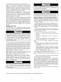
SAFETY
67
Wiring
........
67
CONSIDERATIONS
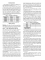
Installing,
starting
up, and servicing
air-conditioning
equipment can be hazardous due to system pressures, electrical
components, and equipment location.
Only trained, qualified installers and service mechanics
should install, start up, and service this equipment.
Untrained personnel can perform basic maintenance functions such as cleaning coils. All other operations should be
performed by trained service personnel.
When working on the equipment, observe precautions in the
literature and on tags, stickers, and labels attached to the
equipment.
• Follow all safety codes.
• Keep quenching cloth and fire extinguisher nearby when
brazing.
• Wear safety glasses and work gloves.
• Use care in handling,
rigging,
and setting
bulky
equipment.
42
Electrical shock can cause personal injury and death. Shut
off all power to this equipment during installation. There
may be more than one disconnect switch. Tag all disconnect locations to alert others not to restore power until work
is completed.
53
66
IMPORTANT:
This equipment generates, uses, and can
radiate radio frequency energy and if not installed and
used in accordance with these instructions may cause
radio interference. It has been tested and found to comply
with the limits of a Class A computing device as defined
by FCC (Federal Colmnunications
Colmnission, U.S.A.)
regulations, Subpart J of Part 15, which are designed to
provide reasonable protection against such interference
when operated in a colrnnercial enviromnent.
This system uses Puron :R:refrigerant (R-410A), which has
higher pressures than R-22 and other refrigerants. No other
refrigerant can be used in this system. Failure to use gage
set, hoses, and recovery systems designed to handle Puron
refrigerant (R-410A) may result in equipment damage or
personal injury. If unsure about equipment,
consult the
equipment manufacturer.
Manufacturer reserves the right to discontinue, or change at any time, specifications or designs without notice and without incurring obligations.
Catalog No. 04-53300093-01
Printed in U.S.A.
Form 30RB-18SI
Pg 1
2-12
Replaces: 30RB-17SI
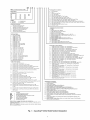
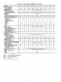
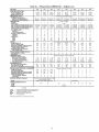
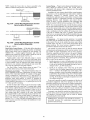
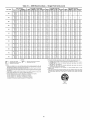
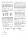
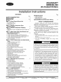
INTRODUCTION
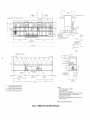
These instructions cover installation of 30RB060-390 aircooled liquid chillers with electronic controls and units with
factory-installed options (FlOPs). See Fig. 1.
NOTE: Unit sizes 315-390 are modular units that are shipped
in separate sections as modules A or B as noted in position 8 of
the unit model nomenclature. Installation directions specific to
these units are noted in these instructions. For modules 315A,
315B, 330A, 330B, 345A, 345B, and 360B, follow all general
instructions as noted for unit sizes 30RB160-170. For modules,
360A, 390A, and 390B follow instructions for 30RB190. See
Table 1 for a listing of unit sizes and modular combinations.
NOTE: The nameplate for modular units contains only the first
two digits in the model number. For example, 315A and 315B
nameplates read 31A and 3lB.
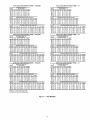
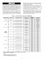
Table 1 -- Modular Combinations
MODULE UNITS
MODULE A
MODULE B
30RBA315
30RBA160
30RBA160
30RBA330
30RBA170
30RBA160
30RBA345
30RBA170
30RBA170
30RBA360
30RBA190
30RBA170
30RBA390
30RBA190
30RBA190
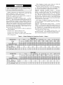
NOTE: An "A" in the model number indicates the design series,
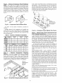
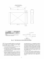
NOTE: The 19/16 in. (40 lnrn) dimension in Fig. 23 is not the
same dimension as the 1.42 in. (36 lnrn) flange that is turned
under the base rail in Fig. 22.
Bolt the unit securely to pad or rails. If vibration isolators
(field-supplied) are required for a particular installation, refer to
unit weight distribution in Fig. 21 to aid in the proper selection
of isolators. The 30RB units can be mounted directly on spring
isolators. For each unit or module, the final unit location must
be level so that oil will equalize properly.
RIGGING UNIT -- The 30RB060-390 units are designed for
overhead rigging and it is important that this method be
used. Holes are provided in frame base channels, marked for
rigging (see rigging label on unit). It is recolnrnended
that
field-supplied shackles be used to facilitate lifting. Secure the
shackles to the base rails at the points noted on the rigging
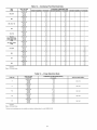
label. See Table 2 for the number of lifting points for each unit.
Do not use a forklift truck to move the units.
Table 2 -- Number of Lifting Points
INSTALLATION
Storage
-- If the unit is to be stored for a period of time
before installation or start-up, be sure to protect the machine
from construction dirt and moisture. Keep protective shipping
covers in place until machine is ready for installation.
Step 1 E Place, Rig and Mount the Unit
NOTE: Inspect the unit upon arrival for damage. If damage
found, file a claim right away with the shipping company.
loaded at the mounting points. The base rail is made from steel,
which is formed into what is shown in Fig. 22. See Fig. 2-20
for locations of mounting points. At the mounting points, a Ushaped channel is welded into the base rail to provide a flat
plate for mounting. See Fig. 23 for mounting plate dimensions.
The 19/16 in. (40 lnrn) dimension shown is to the mounting hole
from the outside edge of the rail.
30RB
NUMBER OF LIFTING POINTS
060-110
4
120-150
6
160-300
8
315A, 315B, 330A, 330B,
345A, 345B, 360A
6
360B, 390A, 390B
8
is
PLACING UNITWhen considering location for the unit,
be sure to consult National Electrical Code (NEC, U.S.A.) and
local code requirements.
Allow sufficient space for airflow,
wiring, piping, and service. See Fig. 2-20. Be sure surface beneath the unit is level, and is capable of supporting the operating weight of the unit. See Fig. 21 and Tables 2-4B for unit lifting points, mounting and operating weights.
Locate the unit so that the condenser airflow is unrestricted
both above and on the sides of the unit. Airflow and service
clearances are 6 ft (1.8 m) around the unit. Acceptable clearance on the cooler connection side or end opposite the control
box unit can be reduced to 3 ft (1 m) without sacrificing performance as long as the remaining three sides are unrestricted. Acceptable clearance on the side with a control box can be reduced to 4 ft (1.3 m) due to NEC regulations, without sacrificing performance
as long as the remaining three sides are
unrestricted. Provide ample room for servicing and removing
cooler. See Fig. 2-20 for required clearances. Local codes for
clearances take precedence
over the manufacturer's
recommendations when local codes call for greater clearances.
Modular units (30RB315-390) must be installed with a minimum separation end to end of 4 ft (1.3 m) for airflow and service clearance along with NEC regulations.
If multiple units are installed at the same site, a separation of
10 ft (3 m) between the sides of the machines is required to
maintain proper airflow and minimize the chances of condenser air recirculation.
MOUNTING UNIT -- The unit may be mounted on a level
pad directly on the base rails, on rails along the long axis of the
machine, or on vibration isolation springs. For all units, ensure
placement area is strong enough to support unit operating
weight. Mounting holes are provided for securing the unit to
the pad or vibration isolation springs. The base rail can be point
Use spreader bars to keep cables or chains clear of unit
sides. As further protection plywood sheets may be placed
against sides of unit, behind cables or chains. Run cables or
chains to a central suspension point so that angle from horizontal is not less than 45 degrees. Raise and set unit down carefully. See Fig. 24 and 25 for rigging centers of gravity.
Each module of the 30RB315-390 units must be rigged separately. When placing unit modules for unit sizes 315-390,
make sure modules are placed to permit access to the control
boxes for each module.
For shipping, some domestic units and all export units are
mounted on a wooden skid under entire base of unit. Skid can
be removed before unit is moved to installation site. Lift the
unit from above to remove skid. See Fig. 24 and 25 for rigging
center of gravity. On export units, the top skid can be used as
the spreader bars. If the unit was shipped with a shipping bag,
the bag must be removed to gain access to the rigging holes in
the base rail. On export units with a full crate, the crate sides
must be removed to aid in rigging.
If overhead rigging is not available, the unit can be moved
on rollers or dragged. When unit is moved on rollers, the unit
skid, if equipped, must be removed. To lift the unit, use jacks at
the rigging points. Use a minimum number of rollers to distribute the load such that the rollers are no more than 6 feet (1.8 m)
apart. If the unit is to be dragged, lift the unit as described
above, and place unit on a pad. Apply moving force to the pad,
and not the unit. When in its final location, raise the unit and
remove the pad.
If the unit was shipped with coil protection, it must be
removed before start-up. The shipping bag for export units
must be removed before start-up.
NOTE: If the application includes a remote-mounted
cooler
option, follow the instructions included with the accessory for
cooler placement and refrigerant piping.
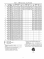
30RB - Air-Cooled
AquaSnap®
Chiller
PackaginglSecurity
L
O
1
3
4
5
7
8
9
C
D
F
H
J
K
Design Series
Nominal
060
070
080
090
100
Sizes
110
120
130
150
160
Voltage
1 - 575-3-60
2 - 380=3=60
170
190
210
225
250
275
300
315"
330*
345*
360*
390*
5 - 208/230-3-60
6 - 460-3-60
Condenser
Coil Option
- - Aluminum
Fin/CopperTube
0 - Copper Fin/Copper Tube
1 - Aluminum
Pre-Coat Fin/CopperTube
2 - Aluminum
E-Coat Fin/CopperTube
3 - Copper E-Coat Fin/Copper Tube
4 - Microchannel
(MCHX)
5 - E-Coat, Microchannel
(MCHX)
Single Pump, 7.5 HPwithVFD
Single Pump, 10 HP with VFD
I{ MN -
Single Pump, 15 HP with VFD
Dual Pump, 3 HP with VFD
Dual Pump, 5 HPwithVFD
P T -
Dual Pump, 7.5 HP, Low Head with VFD
Dual Pump, 7.5 HP, High Head with VFD
Q - Dual Pump, 10 HP with VFD
R - Dual Pump, 15 HP with VFD
Z - Special order designation
Cooler
/ Brine
Options
- - Integral Cooler, CRN (Canada)
0 - Integral Cooler, Cooler Heater, CRN (Canada)
4 - Integral Cooler, Micrechannel (MCHX), CRN (Canada)
5 - Integral Cooler, Cooler Heater, Microchannel (MCHX), CRN (Canada)
£ - IntegralCooler, Med.Temperature
Brine, CRN (Canada)
B - Integral Cooler, Cooler Heater, Med. Temperature Brine, CRN (Canada)
D-Integ
ral Cooler, Meal. Temperatu re Brine, Microchannel (MCHX),
CRN (Canada)
F - Integral Cooler, Cooler Heater, Med. Temperature
Micrechannel (MCHX), CRN (Canada)
Brine,
G - Integral Cooler, no CRN
H - Integral Cooler, Cooler Heater, no CRN
K - Integral Cooler, Micrechannel (MCHX), no CRN
L - Integral Cooler, Cooler Heater, Microchannel (MCHX), no CRN
M- Integral Cooler, Med. Temperatu re Brine, no CRN
N - Integral Cooler, Cooler Heater, Med. Temperature Brine, no CRN
P- IntegralCooler, Med.Temperature
Brine, Microchannel(MCHX),no
CRN
Q - Integral Cooler, Cooler Heater, Med. Temperature Brine,
Micrechannel (MCHX), no CRN
R - Integral Cooler, Micrechannel (MCHX), Heat Recovery, no CRN
S - Integral Cooler, Cooler Heater, Microchannel
no CRN
(MCHX), Heat Recovery,
T - Integral Cooler, Micrechannel (MCHX), Heat Recovery, CRN (Canada)
V - Integral Cooler, Cooler Heater, Microchannel (MCHX), Heat Recovery,
CRN (Canada)
LEGEND
CRN
EMM
GFI-CO
LON
SCCR
VFD
XL
--------
Canadian Registration Number
Energy Management
Module
Ground Fault Interrupting Convenience
Local Operating Network
Short Circuit Current Hating
Variable Frequency Device
Across-the-Line
Start
Outlet
*Refer to Table 1 on page 2 for modular unit combinations
1-Sponsored by ASHRAE (American Society of Heating, Refrigerating,
Conditioning
Engineers).
NOTE: A "Z" in position 11 indicates
do not correspond to tables.
a special
Options
No Packaging
Skid
Skid, Top Crate, Bag
Coil Trim Panels
Skid, Coil Trim Panels
Skid, Top Crate, Bag, Coil Trim Panels
Coil Trim Panels, Upper and Lower Grilles
Skid, Coil Trim Panels, Upper and Lower Grilles
Skid, Top Crate, Bag, Coil Trim Panels, Upper and Lower Grilles
Trim Panels, Upper and Lower Grilles, Upper Hail Guards
Skid, Coil Trim Panels, Upper Grilles and Lower Grilles, Upper Hail Guards
Skid, Top Crate, Bag, Trim Panels, Upper and Lower Grilles, Upper Hail Guards
Skid, Full End Covers
Skid, Top Crate, Bag, Full End Covers
Full End Covers
Controls/Communication
Option
- - None
0 - EMM
1 - Remote Service Port, GFI-OO
2 - EMM, Remote Service Port, GFI-CO
3 - BACnett Communication
4 - BACnet Communication,
EMM
5 - BACnet Communication,
Remote Service Port, GFI-CO
6 - BACnet Communication,
EMM, Remote Service Port, GFI-CO
7 - BACnet Translator
8 - BACnet Translator, EMM
9 - BACnet Translator, Remote Service Port, GFI-CO
B- BACnet Translator, EMM, Remote Service Port, GFI-CO
H - LON Translator
J - LON Translator, EMM
K- LON Translator, Remote Service Port, GFI-CO
L - LON Translator, EMM, Remote Service Port, GFI=CO
Hydronioe Option
= - No Pump Installed
0 - Single Pump, 3 HP
1 - Single Pump, 5 HP
2 - Single Pump, 7.5 HP
3 - Single Pump, 10 HP
4 - Single Pump, 15 HP
6 - Dual Pump, 3 HP
7 - Dual Pump, 5 HP
8 - Dual Pump, 7.5 HP, Low Head
9 - Dual Pump, 7.5 HP, High Head
B - Dual Pump, 10 HP
C - Dual Pump,15 HP
F - Single Pump, 3 HP with VFD
G - Single Pump, 5 HP with VFD
H J -
-
order machine.
Electrical/Low
Sound Options
- - Single Point Power Connections_ XL, Terminal Block
O - Single Point Power Connections_ XL, Terminal Block_ High SCCR
3 - Dual Point Power Connections_ XL, Terminal Block
4 - Dual Point Power Connections_ XL, Terminal Block, High SCCR
7 - Single Point Power Cennections_ XL, Non-Fused Disconnect
8 - Single Point Power, XL_ Non-Fused DisconnecL High SCCR
C - Dual Point Power, XL_ Non-Fused Disconnect
D - Dual Point Power, XL, Non-Fused DisconnecL High SCCR
G - Single Point Power Connections_ XL Terminal Block_ Cmpr Blankets
H - Single Point Power Connections_ XL Terminal Block_ Cmpr Blankets, High SCCR
J - Dual Point Power Connections_ XL Terminal Block, Cmpr Blankets
K - Dual Point Power Connections_ XL Terminal Block, Cmpr Blankets, High SCCR
L - Single Point Power Connections,
XL Non-Fused Disconnect, Cmpr Blankets
M - Single Point Power Connections,
XL Non-Fused Disconnect,
Cmpr Blankets, High SCCR
N - Dual Point Power, XL, Non-Fused Disconnect, Cmpr Blankets
P - Dual Point Power, XL, Non-Fused Disconnect, Cmpr Blankets, High SCCR
Q - Single Point Power Connections,
XL, Terminal Block, Cmpr Blankets,
Cmpr Enclosures
R - Single Point Power Connections,
XL, Terminal Block, Cmpr Blankets,
Cmpr Enclosures, High SCCR
S - Dual Point Power Connections, XL, Terminal Block, Cmpr Blankets,
Cmpr Enclosures
T - Dual Point Power Connections, XL, Terminal Block, Cmpr Blankets,
Cmpr Enclosures, High SCCR
V - Single Point Power Connections,
XL, Non-Fused Disconnect,
Cmpr Blankets, Cmpr Enclosures
W - Single Point Power Connections,
XL, Non-Fused Disconnect,
Cmpr Blankets, Cmpr Enclosures, High SCCR
X - Dual Point Power, XL, Non-Fused Disconnect, Cmpr Blankets,
Cmpr Enclosures
Y - Dual Point Power, XL, Non-Fused Disconnect, Cmpr Blankets,
Cmpr Enclosures, High SCCR
Refrigeration Circuit Option
- - No Suction Line insulation
0 - Suction Insulation
t - Suction Service Valves
2 - Low Ambient Head Pressure Control Operation
3 - Suction Insulation, Suction Service Valves
4 - Suction Insulation, Low Ambient Head Pressure Control Operation
5 - Suction Service Valves, Low Ambient Head Pressure Control Operation
6 - Suction Insulation, Service Valves, Low Ambient Head Pressure Control Operation
7 - Minimum Load Control
8 - Suction Insulation, Minimum Load Control Operation
9 - Suction Service Valves, Minimum Load Control Operation
B - Low Ambient Operation, Minimum Load Control Operation
C - Suction Insulation, Suction Service Valves, Minimum Load Control Operation
D - Suction insulation, Low Ambient Head Pressure Control Operation, Minimum Load Control
Operation
F - Suction Service Valves, Low Ambient Head Pressure Control Operation, Minimum Load
Control Operation
G - Suction Insulation, Suction Service Valves, Low Ambient Head Pressure Control Operation,
Minimum Load Control Operation
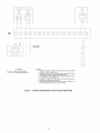
and Air
Digits following
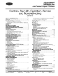
Fig. 1 -- AquaSnap ® Chiller Model Number Designation
1447
81570]
_
_
"
"l
C_{'Tj_F
'
....
r
.............4_
COOLED
T8RE UIII_ __Y---: -- _IIIi_
L
8ERVIGEAREA
:IlIL:_--_',_
_11#
J
DIGGING
¢3800
-
_!o_
,L,oooo_i
p_
4:_
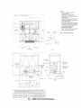
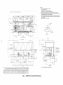
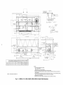
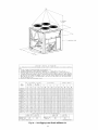
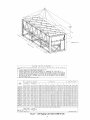
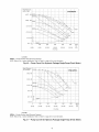
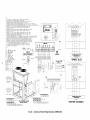
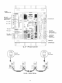
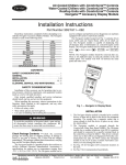
NOTES:
1. Unit must have clearances as follows:
Top -- Do not restrict.
Sides and End -- 6' from solid surface.
2. All pumps have drains located at the bottom of volute
for draining.
3. Temperature
relief devices located on suction line,
liquid line and filter drier of each circuit and have 114"
flare connection.
4. Units without a pump package have the same leaving
water connection,
Y and Z dimensions
(entering
water), and Pump Discharge X dimensions as units
with a pump package.
Dimensions are in mm [inches].
5.
6. Allow 8 ft (2.4 m) of service access on either side of
unit for condenser coil removal.
_
) t
LRLRL80000
_///////////////_Sf/JA
l _''%_F_0%LE
1787]
41447
[1682]
281[ 06103 _
i_18_
[
PIPING
C?IL
ENTRANCE AREA'
SERVICE. ARE_..........
"F
",
AIR
DETAIL
A
SCALE
1:2
FLOW
I
I-- D438
48--1
[96
00]
COIL SERVICE AREA
[
228137
[8982]
4'
_ALL
VICTAULIC
860
93
89]
J_
,801
21573
[840]
DETAIL
A
PD X
40889
116i0]
408 89
[6
O]
[94221
IEIGHl
MAX
WEIGH1
_AX WEIGHT
CUIAL
Ib/k9
CUIAL
Ib/k9 PU_P
CUICU
Ibft9
CUICU
Ib/k9 PUMP
MCHX
Ib/t9
MCHX
Ib/k9P_M9
9088-060
41!1
1869
4944
2247
4595
2088
5426
2466
9788
_716
4616
2094
1!04
[4582]
1098
[4086]
6756
[26
6]
3099
[122]
9581
[139]
9810
[150]
4826
[190]
1880
[74]
9ORS-OHO
4917
1992
5150
2641
4799
2181
5632
2560
3978
1804
4811
2182
1165
[4586]
1013
[3988]
6758
[266]
3899
[122]
9581
[1_9]
3810
[150]
4826
[190]
1880
[74]
MCHX --
MAX
WEIGHT
Microchannel
WEIGHT
Condenser
CERTER
_M
CGx
lINCH]
OF
GRAVITY
_M
COy
lINCH]
PU_P
X25
SUCTION
::H25
v
(P8)
:9=!25
PUMP
:9=X25
DISCHAR6E
::1:_25
(PD)
±!25
Coil
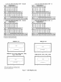
Fig. 2 -- 30RB060H 070 Air-Cooled Chiller Dimensions
ONTROLIPOWED
VOLTAGES BOX
718' KNOCKOUTTO BE
_--USED
FOR LOCATING
FIELD POWER WIRING
i
ENTERING WATER
WEIGHT
HOLE
[1501
I RAChel
:
1748]
19000
qH_
¢O_4MUNICATIONS
OPTION KNOCKOUT
FOR 1/2"
CONDUIT
[9
33650
[1825]
70]
I
k-2159 89
[88 04]
8809
[1,50]
94914
[37 371
--
ISERVICE AREA 121921480]
FROM EACH SIDE OF THE UNIT
I
T
J/x_\L.fFA_u__ CONtRT'Rottll
I
14478
[5700]
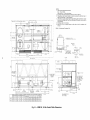
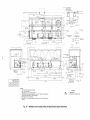
RIGGING
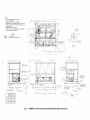
NOTES:
1. Unit must have clearances as follows:
Top -- Do not restrict.
Sides and End -- 6' from solid surface.
2. All pumps have drains located at the
bottom of volute for draining.
3. Temperature relief devices located on
suction line, liquid line and filter drier
of each circuit and have 1/4" flare connection.
4. Units without a pump package have
the same leaving water connection, Y
and Z dimensions (entering water),
and Pump Discharge X dimensions
as units with a pump package.
5. Dimensions are in mm [inches].
6. Allow 8 ft (2.4 m) of service access on
either side of unit for condenser coil
removal.
F OOLER'FTU
'
SERVICE
AREA
[0751
/
223608
[8803]
I__i.....
78834
[}_ 04]
DETAIL
SCALE
A
11:32
20_2221871
I
[787]
PSz 29047
:[1107]
MOUNTING
L
....
PIPING
40876
[15901
[66 64]
ENTRANCE AREA
COIL SERVICE
AREA
AIR FLOW
243840
[9600]
SCROLLING
COOLER VENT
1/4"
NTP_
228187
[8982]
NO PUMP PACKAGE
ENTERING WATER
VICTAULIC
<SEE NOTE 4)
_4"
PUMP
4"
¢
AREA
IARQUEE_
_ISPLAY
FIELD CONTROL
_
n
WIRING-
n
POWERBOX 290V
_CONTROL/POWER
BOX
380V,460V,GTGV
FANELECTRICAL
(230VONLY)BOX
(FEB)
VICTAULIC
_SEE
OETAIL
/
A
_7/8"
KNOCKOUT TO HE
USED FOR LOCATING
FIELD POWER WIRING
-
38688
[1523]
[8491
670 ]
,
FOR 1/2'
CONDUIT
OPTION KNOCKOUT
_
L
94914
[57
•
[1610]
[1610]
[9422]
Ib/k_
3ONB-OHO
MCHX --
4600
2091
Microchannel
Ib/I
5523
2511
g
WEIGH1
CU/CU
Ib/I
5082
2310
Condenser
_AX WEIGHT
;UfCU PUMP
9
Ib/k
6005
2730
9
WEIGHI
MCHX
Ib/k
4267
1934
9
_AX WEIGHT
MCHX
PUMP
CENTER OF GRAVITY
CGx
PUMP SUCTION (PS)
PUMP OISCBARGE [PD)
CGp
Ib/k_
5190
2355
Coil
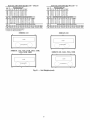
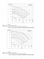
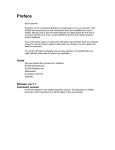
Fig. 3 -- 30RB080 Air-Cooled Chiller Dimensions
215989
[85 035]
UNIT _40UNTI NG
37]
[748]
90
00
33650
[1328]
,
BACneI COMMUNICATION _
[20521
MAX WEIGHT
CUfAL
PUMP
HOLE
:
COIL SERVICE
WEIGHT
CU/AL
HOLE
CGy
9809
11 50]
SERVICE
AREA
_2192148G]
FRoM
iACHS_OiSrT_&Z
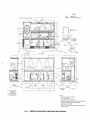
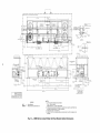
NOTES:
1. Unit must have clearances as follows:
Top -- Do not restrict.
Sides and End -- 6' from solid surface.
2. Temperature relief devices located on suction line,
liquid line and filter drier of each circuit and have 1/4"
flare connection.
3. Dimensions are in mm [inches].
4. Allow 8 ft (2.4 m) of service access on either side of
unit for condenser coil removal.
RIGGING
--¢
114961
J
CG7
_-
1447
81570]
1891 29
[74 46]
I
LEGEND
Heat Reclaim
Microchannel Condenser
Pressure Relief Valve
HR
-MCHX -PRV
--
;
COOLER TUBE
I
SERVICE
t
2236
AREA
'
08
[88 03]
Coil
_
2OO OO
[787]
J
WOUNTING
HOLE
DETAILA
SCALE
12680
[499]
t
1:2
EAHR!_8 E
I
k_I[
138721
154611
8533
[3361
IIII_
' H _!!_ES
I
II
i
r
612 16 [2412]
i
PIPING ENTRANCE AREA :
I
HOLE
3809
_
--
144777
2052,75
[8082]
[57
_]
OO]
AIR FLOW
I
1
E II
"
1
Q'h
'_--_1
_'_
"--COOLER ENTERING
WATER 4" VICTAULIC
--COOLER LEAVING
WATER 4 I VICTAULIC
-_ONDERSER
_.ql'"
.
;
_
WATER
228
37
189 82]
LEAVING
30"
VICTADLIC
/-_ONTROL/POWER
ALL VOLTAGES
80X
WATER 3 0 I VICTAULIC
f
[23
:
_SEE
_-
_,_*
_'_I
" I --CONDENSER
DETAIL
25
•
-,
_,
CONDENSER VENT 1/4'
CONDENSER
DRAIN
[181651
47375
,
Z/I
37601
_718"
RNOCROUT TO BE
USED FOR LOCATING
FIELD POWER WIRING
I
30]
5 '9'
l 1
i
A
ENTERING
I_1
['2,411
CO0
2
[13571
2X 67481
[26
57]
R
3/4"
235
[40 62]
1082
[4H HO]
30R_.O10
4898
2221
198
[4! 17]
1093
[43 03]
30RlJ-080
587
2353
199
[4720]
1120
[_410]
I I".L_
37601
11480]
NPT
45663
[17 98]
9000
4091
[1 61]
"_OR[1 /2ll
c_NOUIT
2154[/
[848]
[94.22]
Fig. 4 -- 30RB060-080 Air-Cooled
_[
33650
[1325]
45663
WEIGHT CENTER OF GRAVITY
_CHX
CGx
CGy
Iblk9 _M lINCH] M_ lINCH]
4703
HORB-060 2133
_'_//'
t
,
RPT
'
[748]
21573
[849]
Chiller with Heat Reclaim Option Dimensions
_J_ZHJ]
SERVICE
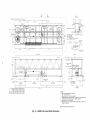
NOTES:
1. Unit must have clearances as follows:
Top -- Do not restrict.
Sides and End -- 6' from solid surface.
2. All pumps have drains located at the bottom of
volute for draining.
3. Temperature relief devices located on suction
line, liquid line and filter drier of each circuit and
have 1/4" flare connection.
4. Units without a pump package have the same
leaving water connection, Y and Z dimensions
(entering water), and Pump Discharge X dimensions as units with a pump package.
5. Dimensions are in mm [inches].
6. Allow 8 ft (2.4 m) of service access on either
side of unit for condenser coil removal.
AREA 1219 2148 O] FROM EACH SIDE OF THE UNIT
CG x
e
,
....
CGy
i
223608
DETAIL
_
RIGGING
HOLE
MCHX -:
_--
Microchannel
---i
_
i_
I
188031
78835
3104]
"T
[787]
163207
164251
ENTRANCE
1017 46
[40 06]
PIPING
7 55
[5691]
AREA
AIR
;
FLOW
fl
II
"
--4
#
SCROLLING MAROUEE-DISPLAY
_
228137
[89821
FIELD
PUMP PACKA(
LEAVING WATER
CONTROL WIRING
\_.,
PUMP PACKAGE
ENTERING WATER
COOLER
3/4"
NPT
(SEE
NOTE 4)
4" VICTAULIC
F!
k\
O
II
II
<
....
43
_ _
I
FPOWEH
/
!!
/
FIELD
T
86400
[3402]
[7481
[1543]
39188
PACKAGE
ENTERING WATER
_" VICTAULIC
24636
[970]
_SEE
40889
[1610]
,
___
215630
[8489]
UNIT MOUNTING
DETAIL
276930
UNIT MOUNTING
PD×
29220
[109031
t
pS x
99244
[39071
L_
219510
[86421
[11 501
358708
[14i221
WEIGHT
MAX
WEIGH1
CUIAL
Ib/kR
CU/AL
Ib/kg PHMF
30R8-090
5992
2697
6855
3116
5ORH-]OO
6155
2798
7078
5217
WEIGHT
CUICN
IDleR
MAX
WEIGHT
WEIGHT
_AX
WEIGHT
CENTER
CU/CU
Ib/kg PUMP
MCHX
Ib/k9
MCHX
Ib/k9 PUMP
MM
6656
3096
7579
3445
5779
2472
6572
2890
1625
[640]
6879
3127
7809
3547
5663
2569
6586
2987
i614
[635]
CGx
lINCH[
OF
GRAVITY
MM
PUMP
SUCTION
PUMP DISCHARGE (PD}
(PSI
±X25
±25Y
• ! 25
i X25
±Y25
±Z25
1017
[4OO]
13894
[547]
3099
[199]
9551
[19
9]
1097 9
[43 R]
497¸8
[19 0]
_702
[67]
999
[993]
13894
[547]
309
[122]
353
[159]
I097¸3
[432[
497¸8
[INOI
170¸2
[6¸7[
CGy
lINCH[
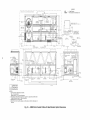
Fig. 5 --30RB090,
9
1
100 Air-Cooled Chiller Dimensions
_i
'
_
19000
-- 33650
[1325]
_
BOX 230V
380V,460V,575V
CONTROL/POWER
3989
[157]
POWER WIRING
Condenser
Coil
SERVICE
AREA i219
2148
O] FROM
EACH
"1
CG X
rOe ¸
_OR_.
_
NOTES:
1. Unit must have clearances as follows:
Top -- Do not restrict.
Sides and End --6' from solid surface.
Airflow Side -- 8' required for coil service area.
2. All pumps have drains located at the bottom of
volute for draining.
3. Temperature relief devices ocated on suction line,
liquid line and filter drier of each circuit and have
V4" flare connection.
4. No pump package leaving water connection
is
same size and has same Y and Z dimensions as
entering water. Also has same PDx dimension as
pump package.
5. Dimensions are in mm [inches].
SIDE OF THE UNIT
l
RIGGING
CGy
HOLE
¢3800
[150]
iA4781570]
...<-_j,
COOLER TUBE
SERVICE
AREA
- ]-¢i_
_
2236
[88
t
LL_
PD z
MCHX --
76194
[30OO]
Microchannel
17871
PS z
e__, _/////////__///,/////J//////_//_
-
22484
[885]
-
-
DETAIL
SCALE 3:16
,_le
244609
-
-
916,15
-
PIPING
196301
ENTRANCE
I
136,071
AREA
]
COIL SERVICE AREA
AIR
fl
196o01
2438
40
[-_
FLOW
' ' : '
' ': "
Go
COIL
S-ERDICE
AREA
_
[_
H
I
i
COOLER
VENT
1/4"
NPT
228137
[8982]
SCROLLING
,FIELD
PUMP
MARQUEE- _
DISPLAY
CONTROL
WIRING-_,
,RUMR
,ACKAO
ENTERING
WATER
6" VICTAULIC
<SEE NOTE 4)
n
I
'
860.8'
n
_'_
I
I
"tl
i FAN(E2L_EoCvTRoI_LAyL)
BOX
...." ' : ::;
n
I
u
I
n
_>\I
_-'_i
POWER BOX 230V
CONTROL/POWER
BOX
380V,460V,S75V
[I
IqJl
Iq
/
/f(:
//
/ ii /
_3;_"_7"_
r,_'J_t,-(_{--_'kl
/
_718"
KNOCKOUT TO BE
USED FOR LOCATING
FIELD POWER WIRING
II/
I)_
/
[748]
19000
r-
3/4"
NPT
- _9188
6" VICTAULIC
COOLER ORAIN
51582
pD x
40889
[1610]
I
.
21_73/
[ls:43]
"
UNIT
MOUNTING
/
'
RAChel
COMMUNICATION_
OPTION KNOCKOUT
FOR /2"
CONDUIT
[20311
276930
[I09031
/
[8491
SEE DETAIL
408.89
[16.i0]
PS x
I
I
2A6: ,. :!.
[9
I
70]
I
_
2728,56
[10742]
9587 08
[i41,22]
WEIGHT MAX WEIGHT WEIGHT
4AX WEIGHT WEIGHT _AX WEIGHT
CUIAL
Ib/k9
6519 CUIAL
Ib/k9
7442PUMP CUICU
Ib/k9
7243
2963
3383
3292
:UICU
Ib/k9PU_P
8166
3712
6027
MCHX
Ib/k9
2734
NCHX
Ib/k9
6950
PUMP
3162
CENTER OF GRAVITY
PUMP SUCTION
MM[67
1713
CGx
[INCH]44]
HM
[3925][INCH]
CG
9977
8560
±X25
[337]
[I11]
4-!25
2819
(PS)
4-!
60.925
[R4]
215630
[84 89]
UNIT MOUNTING
PUMP DISCHARGE (PD)
[134]
4-!25
3404
4-Y25
9912
[164]
Fig. 6 --30RB110
2337
4-!25
[92]
Air-Cooled Chiller Dimensions
-
:
33650
[i3.25]
--
93835
[36
I
30RR-110
/
94]
3989
[1.571
Condenser
Coil
NOTES:
1. Unit must have clearances as follows:
Top -- Do not restrict.
Sides and End -- 6' from solid surface.
2. Temperature relief devices located on suction line,
liquid line and filter drier of each circuit and have 1/4"
flare connection.
3. Dimensions are in mm [inches].
4. Allow 8 ft (2.4 m) of service access on either side of
unit for condenser coil removal.
SERVICE AREA 1R19 R[48 O] FROM EACH SIDE OF THE UNIT
--1[;!43_;
.
,
,
--
"1
1.1 _
- _cG,
T
A47,[STDI
LEGEND
HR
MCHX
---
RIGGING HOLE
_/¢SHDD
'
223608
Heat Reclaim
Microchannel Condenser
[88
[150 1
4500
[177]
03] /
Coil
!t_:_,
_
)))
II II
,Yq
II II
)
[3941
T_LE
[78Tl
PIPIIG
ENTRANCE
_j_
ARE __
E
o__
=e ........
[] __
T
.....
i
SERVICEAREAi
I
:
212360
[83 61 ]
144780
DETAIL
SCALE 3:15
i
L_
[57 OO] :
I
......................
AIR FLOW
.q
_D
DISPLAY
SCROLLING _ARQUEE- __
WATER 30"
VICTAULIC
FIELD CONTROL
[8982]
n
n
L
I
WIPING-
FA_'_EpI'KEoCvTRoINCZ_YL}BOX
II\ i
:..
...
.....
,
.: ::.!?
f
J
215 73
[849]
1
"
II
•
[748]
19000
Z_
COOLER
_7/8"
DETAIL
H8
EONOENGERENJN:"L/
[i3
59]
55]
39_88
_
_0889
[ 15 1O ]
[1610]
I,
[lORD3]
F
_']
:
)/246[
8ACrei
COMMUNICATION_
OPTION KNOCKOUT
FOR /2"
CONDUIT
325741
[12824]
[9
7133
3256
1759
[6955]
1064
[41HP]
3HRK-IOC 6769
3071
i576
[5598]
1067
[4200]
30RH-OPC 6555
29YA
i689
[5650]
1088
[A28A]
Fig. 7-
3587 08
114122[
33550
[1325]
L
3989
[15701
Jl_
30RB090-110 Air-Cooled Chiller with Heat Reclaim Option Dimensions
KNOCKOUTTO 8E
USED FOR LOCATING
FIELD POWER WIRING
70]
93835
[35941
[1241]
WEIGHT CENTER OF GRAVITY
MCH×
CGx
C5
Ib/kg
MM _CH M_
_CH
BORR-HC
POWER BOX 230V
//_CONTROLIPOWER
80X
380V,46OV,S75V
215530
[8_894]
UNIT #OUNTING
_
SERVICE AREA 121921480]
FROM EACH SIDE OF THE UNIT
F
--
NOTES:
1. Unit must have clearances as follows:
Top -- Do not restrict.
Sides and End -- 6' from solid surface.
Airflow side -- 8' required for coil service area.
2. All pumps have drains located at the bottom of volute for draining.
3. Temperature relief devices located on suction line, liquid line and filter drier
of each circuit and have 1/4" flare connection.
4. No pump package leaving water connection is same size and has same Y
and Z dimensions as entering water. Also has same PDx dimension as
pump package.
5. Dimensions are in mm [inches].
CG X
CTSA x
COOLER TUNE
RVICE AREA
RIGGING
HOLE
188 03]
(
l
l
PDz
PBz
!
f
R000N
8.
.871 ,ONINTIN8
ROLE
DETAIL
SCALE
I4R$o,
_gN
_ol RREA
_IRIRG
ENTRANCE
COIL
GENVICE
AREA
[
3;16
INN
03,
AIR FLOW
IgD
ool
_
I _fl I1
243840
COIL
SERVICE
"
1
AREA
COOLER VENT_
I/4" NTP
SCROLLING
228137
[8982]
PUMP PACKAGE
ENTERING WATER
HANOUEE-DISPLAY
:
RUMP
LEAVING WATER
N" VICTAULIC
FIELD
CONTROL WIRING-
_
n
n
n
--POWER
BOX 290V
CONTROL/POWER BOX
380V,4HOV,575V
__
7/8"
KNOCKOUT TO BE
/--USED
FOR LOCATING
FIELD POWER WIRING
_SEE
DETAIL
B64_
[!48]
j
39188
[i543]
198165
[7802]
COOLER DRAIN
314" NPT
PN×
ENTERING WATER
6" VICTAULIC
44092
[17361
215
73
J
BAC_el COMHURICATION_
OPTION KNOCKOUT
FOR I/2" CONDUIT
2970.06
[H6
99]
30RB-12C
30RR-15C
4AX
WEIGHT
WEIGHT
4AX WEINHI
]U/AL PUMF
Ib/kg
CU/CU
IbiS9
MAX
CUICU
PUMP
Ib/kg
WEIGHT
_CHX
Ib/kR
MCBX
PUMP
Ib/kR
7990
3488
8615
9907
8594
5871
9457
4290
7119
3229
8042
3948
8045
3649
8958
4068
9010
4087
9953
4500
7402
3358
8825
3776
CENTER
CGx
M_ :INCH]
OF
GRAVITY
PUMP
SUCTION
(PS)
COy
_M :INCH:
X
/=25
Y
/:25
Z
/=25
2846
[9296]
993
[5909]
18085
[712]
2819
[1!1]
609
[24]
2272
[8945]
988
[5870]
]8085
[712]
2819
[111]
609
[24]
PUHP
DISCHARGE
_PU)
COOLER
_ERVICE
/=XR5
Y
/=95
/=!25
1866_
[598]
5912
[154:
2837
[92]
1447
[570]
1386_
5912
2337
1447B
[92]
[570]
[538]
[_541
3365o
[1325]
701
L
2156¸30
93895
[3H94]
[8489]
UNIT MOUNTING
MCHX -- Microchannel
WEIGH1
CU/AL
Ib/_g
I
[9
3989
[157]
_
[4563]
478]08
[18823]
WEIGHT
/
[1610]
_Ro:ILc??:
ING
[1610]
TUNE
AREA
CTNA
x
MM :INCH]
8
Fig. 8 -- 30RB120 Air-Cooled Chiller Dimensions
900N
Condenser
Coil
J
NOTES:
1. Unit must have clearances as follows:
Top -- Do not restrict.
Sides and End -- 6' from solid surface.
2. Temperature relief devices located on suction line, liquid line and filter drier of each
circuit and have 1/4"flare connection.
3. Dimensions are in mm [inches].
4. Allow 8 ft (2.4 m) of service access on
either side of unit for condenser
coil
removal.
[SERVICE
AREA 1219 2148
HI FROMEACH SIDE OF THE UNIT
]
I
:
_÷OOLE_p_ENT
I
15 94] _
RIGGING
HOLE
.-!447.978,
[
:
COOLER TUBE
I
SERVICE
]
189275
AREA
174
1
52] 2286
4500
[1 771
08
[88.03]
i
[89.371
I
--q
F
i
1
;
,_,.
22 2[
871
MOUN:rI RG HOLE
200 00_
[7871
:
50114
[199F]
PIPING ENTRANCE AREA
',
J
_--HR
I
DETAIL
_
SCALE
3:10
CONDENSER TUBE
SERVICE AREA
_-
t
LEGEND
HR
MCHX
17147
1675]
Heat Reclaim
Microchannel Condenser
--
[104,69]
107010
[4213]
60000
[2362]
PIPING ENTRANCE
Coil
[30001
85904
[3382]
60000
[2362]
PIPING ENTRANCE AREA
AREA
AIR FLOW
I
R
,I......
R
10_DE_;_8
n
SCROLl
VENT
r II"
_
'n I
I
8ACDei COWWUNICATION
_OPTION
KNOCKOUT
FOR 1/2"
CONDUIT
NAROUEE-DISPLAY
FIELD CONTROL
LEAVING WATER
6"OOLER
VICTAULIC
_ I I_ "
WIRING-
228137
18982]
/
POWER 80X 230V
_CONTROLIPOWER
BOX
380V,460V,575V
39188
•
LEAVING WATER
SO' VICTAULIC
......
:,.
:
:-
,:,:
:.:,
:,:.,]
:,.
:
:
/.,.,:
:.:,
.,,.,
USED FOR LOCATING
718" KNOCKOUT
TO BE
FIELD
POWER WIRING
D543]
I
I29i'1 _, _
-+*
COOLER DRAIN
3/4;' NPT
318"
I
b07 19
[19 97]
40889
[16101
198165
178 02]
UNIT WOUNTING
NPT
I
I
I
,,I,
'_&_-_
341098
[134
29]
377358
[148
57]
198165
[78 02]
UNIT WOUNTING
1159 04
[45 63]
--SEE
DETA
i]
1
_
I
I
i
[
408 89
[1610]
3989
[15F]
[188.23]
WEIGHT
CERTER
NCHX
M_
HOHH-120
Ib/kg
8HOH
3813
CGx
lINCH]
[95001
24_3
OF
GRAVITY
MM
19000
1748]_
{'
Ii×'_O,0ENSER
_PORAIN
I
0
738_9I3_:_21
U-
[29
342 96
[1350]
86
CGy
lINCH]
[4287]
IOH9
Fig. 9 -- 30RB120 Air-Cooled Chiller with Heat Reclaim Option Dimensions
21573
1849]
f
.99..701
L- 9_8
3s I
215680
[84 89]
UNIT MOUNTING
[30941
.
33650
[1325]
f
SERVICE
AREA 1219
2[48
O]
FROM
EACH
m,.
SIDE
OF
THE
r
UNIT
=78 i
HOD
]A
OO
,KAK,_
/
.r I
8765
NOTES:
1. Unit must have clearances as follows:
Top -- Do not restrict.
Sides and End -- 6' from solid surface.
2. All pumps have drains located at the bottom of volute for draining.
3. Temperature relief devices located on suction line, liquid line and filter drier of
each circuit and have 1/4" flare connection.
4. Units without a pump package have the same leaving water connection, Y and Z
dimensions (entering water), and Pump Discharge X dimensions as units with a
pump package.
5. Dimensions are in mm [inches].
6. Allow 8 ft (2.4 m) of service access on either side of unit for condenser coil
removal.
_°.
•
,JJ
MCHX -- Microchannel
i! _O_=_ETX_EA
II1°1
_
I'1/
11"1
4F_
/
IJ TI
200 O0-[787]
498.2F
i:
[19
E2]
•
1693
"
[GR
H241 68]88
[127
76_
_
PIPING
ENTRANCE
AREA
116089
[4D
70]
1040
[40
Coil
VIEW A-A
SCALE 13:160
\
!-"-
Condenser
POWER @OR 3DOV,460V,575V (CRT A,8)
POWER DOX D3OV (CKT D)
RIGGING HOLE
¢3800_
J
!
24000
Q
i
._,
[ 5
I1
77]
45 OR
[945]
_J
;De
9_
[150]
51
_'_"HHOGHONTTOOE
__
USEDEONLOGAFING
__
FIELD POWER AIRING
(DUAL
AND
SINGLE
POINTI
lOO DO
[394]
22
[787]
98]
63]
2[
_OUNTIRG
87]
HOLE
DETAIL
Co
AllOW
r
RVICE AREA
SCROLL I_,GAAROUEE-DISPLAY
FIELD
PUMP
29:160
SCALE
=
\
TROL WIRING--ROW
CKT A
PACKAGE
.....
• _;Q_C2f",._:_J
' 1_]
21573
[849]
-718'
HNOCKOUT
(DUAL
39 AR
[15/]
POWER
'H_DR'
/ L____3D3D
_
Fig. 10-
30RB130, 150 Air-Cooled Chiller Dimensions
[36
941
NFD
"
-190
_AC_i COAAUNICATION_
OPTION KNOCKO T
FOR )/2' CO@IT
BE
CIRCUIT _ 380,460,
575V ONLY)
[1283]
PACKAGE
TO
USED FOR LOCATING
FIELD POWER WIRING
(DUAL POINT 230V ONLY)
32596
ENTERING
WATER
6' VICFAULIC
230V ONLY
DO
LEGEND
HR
MCHX
---
Heat Reclaim
Microchannel Condenser
Coil
I
POWER BOX H3OV {CRY B}
POWERBOX 380V,gHOV,DYHV [CRT A,B)
: .I COOLER
TUBE
!iSERN'BBAREA
D31
_/
i
:
:6O0OO
1[BH H2]
PIPING :ENTERANCEAREA
HOOOOJ_-J
'-I
_..%
[78Yl
"
'
_REAI
I
_BSEDI/8" KNOCKOUT
FOR LOCATIRG
TO BE
FIELD POWER WIRING
{DUAL AND SINGLE POINT)
4OOO0
_
[15751
RIGGING HOLE
38 OO _
i_]\BETAIL
[IHO]
VIEW A-A
SCALE 13:IHO
D
29:160
SCALE
I
it
:l/H
lOO nn_
[_ 9_]
OO
I IRBHI
L ..........
#
1
123 HB]
!IP_N.!ENT_RANC!.
AR__EA.
...................
123B21
_1
L4B OR
[177]
.
P__'P.I._OE;'.TBRjR.?E__'R.E.'
- ..............................
i
[31511
[7871
AllOW
MOUNTING HOLE
II
I
POWER BOX 23ON ONLYCRY A
7/8' RNOCROBT TO BE -USED FOR LOCATING
LEAVING WATER
-SCROLLING
DISPLAY
RARQBEE
i_1"
VICTANLIC
ORDENSER
n
\
_'_
96
19
{DUAL
FIELD
POINTPOWER
2HOVWIRING
ONLY)
n
n
n
ALL VOLTAGES
FAN ELECTRICAL(FEB)
90X
/
90
9HI
49
11]
•
-190
09
[1 48]
.+
33659
[192§]
39 89
[1 :::_t
C.....ICATIOR_
UA]T NFLNTINO L'_HS8
9H
[3B 941
3DR
WEIGHT
8814 CERTEROF GRAVITY
_-130 HRR8
NOTES:
1. Unit must have clearances as follows:
Top -- Do not restrict.
Sides and End -- 6' from solid surface.
2. Temperature relief devices located on suction line, liquid line and filter drier of each circuit and have V4" flare connection.
3. Dimensions are in mm [inches].
4. Allow 8 ft (2.4 m) of service access on either side of unit for condenser coil removal.
Fig. 11 --30RB130
Air-Cooled Chiller with Heat Reclaim Option Dimensions
LEGEND
SERVICE
AREA
12_92140H]
FROM
EACH
SIDE
OF THE
HR
MCHX
7A
UNIT
---
Heat Reclaim
Microchannel Condenser
[H440]
PU¢_
Coil
80X DDOV (CRT 8)
POWER 50X DBOV,46OV,RTRV (CHT Ar5)
290880
I
i
SERVICE
COOLER
AREA
TUBE
KNOCKOUT TO DE
USED FOR LOCATING
FIELD POWER WIRING
(DUAL AND SINGLE POINT)
I-OOOOO
[BR6B]
RIGGIRG
HOLE
RDOO
_
5O
[
]
78658
[R979]
SOU
UFTAII
....
SCALE
29:160
B6
[31Sl]
AIR
Do0
[78T]
FLOW
00
I--,_'-_72
8[ 8T]
MOUNTING
BOLE
E
FIELD CONTROL WIRING
SCROLLING
POWER 80x 8ROY ONLYGET A
t_AROREE
718'
81SPLAY
HI,OCEO
USED
Z
FOR
TO
8E
LOCATI
T
G
'
(DUAL FIELD
POINT POWER
2BOY _VIRING
ONLY)
"_ lq
Fl
Fl
{q
OOLER
LEAVING
.. X
.:/.
WATER
: .. : -. ,:,:
:.:, .-:,:,,,_j
..
,;,.,
; ,- ; -,/,.':
;
.;
' ;, ,.'_'-_
8ETAIL
H4R!
....
GE'VENT"'RG'
I I ,,.....
1/4"
NPT
_DX
343
[13
58
53]
_
8H4OO
[34
OR]
..
DDH- I
o
/
iH81HR
_HSlHR
_-
/
i
40889
2x
T6985
[HO31]
--190
.
4'
0RAIR
NRT
DRAIN
Of 8"
UNI_T8 MOUNTING
021
RNIT[70021
MOUNTING
NPT
I=
_118904_
[45
3773
BD]
3909
[157]
58
_
30_8-1Rv
417RRH
478100
[188
8D]
--
9929
4504
NOTES:
1. Unit must have clearances as follows:
Top -- Do not restrict.
Sides and End -- 6' from solid surface.
2. Temperature relief devices located on suction line, liquid line and filter drier
of each circuit and have 1/4" flare connection.
3. Dimensions are in mm [inches].
4. Allow 8 ft (2.4 m) of service access on either side of unit for condenser coil
removal.
Fig. 12-
2186H0
[8469]
UNIT
[16429]
CENTER OF GRAVITY
[748]
1
24636-[H7O]
-
[161G]
_ONDENSE8
OLER
[14887]
WEIGHT
/
.......
30RB150 Air-Cooled Chiller with Heat Reclaim Option Dimensions
MOUNTING
--33650
[IDZ$]
OR
i.....
SERVICE AREA 121921480]
7
I
I
AV
&
KAODKOUTTO BE _
SED FOR LOCATING
FIELD POWER WIRIG
<DUAL AND SIHGLE POIRT)
FROM EACH SIDE OF THE UNIT
POWER BOX 2SOY {CKT R)
POWER BOX
380V,46OV,575V (CKT A,B}
].........................
....
I
I
157001
r
r_
VIEW-A-A
//8"
•
14478
COOLER TUBE
SERVICE AREA
"- " "- :. rrl
C- "-"
@
l
:
24000
19 45]
CGy
200 D0 4,JNOO
1
OR L--"
[7BK]
[1§
"'Z_""",,._SEE
DETAIL
E}
l§]
R2_ 08
/-
RIGGING HOLE
¢3800
[He U3] I
t
RETAIL 3:16
B
SCALE
_/A]
/
[
50]
75558
[29 751
RSz
I
R9z
I
76951
[3030]
E
==CT_
1
l_///_./_///////////////////_.////////////////_///y/////_/_..-I_////////A
i
[58421
[57341
.B3H3_
L----.sogs
3212 K3 PIPING EHTRAHCE AREA
.
,t
[787]
99325
[78 47]
[12H 47]
I
I
COIL SERVICE AREA
,
_
249840
[9HOO]
AIR FLOW_
_1 i'
II
i'
COIL SERVICE AREA
SCROLLING MARQUEE-DISPLAY
n
228137
LEAVING WATER
[89 H2]
6" VICTAULIC
3/A"
:._
OOLER VERT I14' RPT
RPT)
I
ALL
VOLTAGES
I
-_
1
WATER
H' VICTAULIC
{SE NOTE 4)
i"
86400
[84R]
It_
,;i. ,-_
_-
_..,_
'
-
_!-
R38[_\305,
IRA 01HI
H" VICTA LIC
I
UNIT MOUHTIRG
RS x
I
_I _
276_
[i0R
WEIGHT _AX WEIGHT WEIGHT _AX WEIGHT WEIGHT AAX WIIGBl CENTER OF GRAVITY
CUIAL UUIAL PU_P CU/C_ ZU/CU P_MP _CHX _ACHXPU_P
CGx
CG_
Iblk_
Iblk9
......................................
46406
[ H3 94]
30RB-_40
315AIB,330_
PU_APUISCBARGE (PR)
!25
±!25
10264
4666
1151_
523Z
H4!2
5215
_n7
5TNt
94/5
4297
107z0
4860
N045
[120
66]
[39994
13]
BOB 2]
4 [15SRlo] [11
NN/ 7]
2 NR392
42164 3_114
IT1
[_48] [166]
[91]
11846
5385
]807
5567
3052
5933
9799
4443
11044
5009
_la
[122 591
978
[3051
808 4; 381
[71 21 [1R0]
Condenser
Coil
Fig. 13-
_1_
[148]
9000
40889
1i6101
215630
3989
_
[
KK]
_
UNIT MONTIHG
--
33650
[1325]
BAC_¢i COFA_AUAICATION
OPTION KNOCKOUT
FOR 112' CORBUIT
24636
[gYo]
93835
[36 94]
POWER BOX 230V ONLY (CHT A)_
=H!25:1:!25
KORR-_IO
I0_0_
50A•345A/N,KGOJ4B19
MCHX -- Microchannel
°,
-
2HI
PUMP SUCTIO_
±!_5
30[8184'
03]
UNIT MOUNTING
[235
:
4,
422 24
[16 HE]
408 89
[i6 10]
-7/8"
KNOCKOUT TO BE
USED FOR LOCATING
FIELD ROWER WIRING
(DUAL ROIHT 230V OHLY)
_DUAL POWER NFD
CIRCUIT R 380,4HO,KYSV
OHLY)
n
FAN ELECTRICALBOX
(FEB)
FIELB CONTROL WIRING-
297 2 885 92 4Rl_a
[11 71 [K481 [1561
23114
19;1
NOTES:
1. Unit must have clearances as follows:
Top -- Do not restrict•
Sides and End --6' from solid surface•
2. All pumps have drains located at the bottom of volute for draining•
3. Temperature relief devices located on suction line, liquid line and filter drier of each circuit and have VA"
flare connection•
4. Units without a pump package have the same leaving water connection, Y and Z dimensions (entering
water), and Pump Discharge X dimensions as units with a pump package•
5. Dimensions are in mm [inches]•
6. Allow 8 ft (2.4 m) of service access on either side of unit for condenser coil removal•
30RB160, 170, 315A/B, 330A/B, 345A/B, 360B Air-Cooled Chiller Dimensions
SCROLLING _AROUEEDISPLAY
FIELD CONTROL WIRING
2X 503 31
[i0 82]
228
[89 8_]
-_ONOENSER
LEAVING WATER
50"
VICTAULIC
864!00
2x 76985
CONDENSERS
ENTERING WATER
80'
VICTAULIC
19000
[9A81
[34 0R]
.08_1I L
583!81
:i_
8ol ,
343_8_
113,841
K/4'
NRT
2X 34333
-[13 521
RAChel
OPTION KNOCKOUT
FOR 1/2' CONDUIT
[13251
83650
L
24536
[970]
40889
[1610]
WEIGHT
_CHX
Ib/_9
CENTER
_M
CG_
[l_CN]
_M
CGy
lINCH]
30RN-160
3_SAIB,3308
I0991
4986
3124
[122991
30RN-I?O
11315
3168
98_
5_33
[124741
[38821
330A,345AIB,360_
7/8' KNOCKOUT TO BE
USEO FOR LOCATING
FIELD POWER WIRING
_DUAL POINT 230V ONLY)
OF GRAVITY
93835
_'J
[3094]
_001
[394]1
NOTES:
1. Unit must have clearances as follows:
Top -- Do not restrict.
Sides and End -- 6' from solid surface.
2. Temperature relief devices located on suction line, liquid line and filter drier
of each circuit and have VA" flare connection.
3. Dimensions are in mm [inches].
4. Allow 8 ft (2.4 m) of service access on either side of unit for condenser coil
removal.
HR
MCHX
Fig. 14 -- 30RB160,170 Air-Cooled Chiller with Heat Reclaim Option Dimensions
---
LEGEND
Heat Reclaim
Microchannel Condenser
Coil
F--
•I.....
A_7
r SERVICE AREA 1219 2148 O] FRON EACH SIDE OF THE £,NIT
NOTES:
1. Unit must have clearances as follows:
Top -- Do not restrict.
Sides and End --6' from solid surface.
2. All pumps have drains located at the bottom of volute for draining.
3. Temperature relief devices located on suction line, liquid line and
filter drier of each circuit and have 1/4" flare connection.
4. Units without a pump package have the same leaving water connection, Y and Z dimensions (entering water), and Pump Discharge X dimensions as units with a pump package.
5. Allow 8 ft (2.4 m) of service access on either side of unit for condenser coil removal.
6. Dimensions are in mm [inches].
]
VA
,
!
I
"
"1
MCHX -- Microchannel
Condenser
Coil
!
!
I
[3F 811
96040
F!
C 7
\'_-tFt!-J/
I
[SERVICE AREI
2236 08!
I [88 03]|
l
I
==.- -=r
I
LJ
/€::::=11
!
II:::::_\
|
I,
!
I
|
I
b .i
[PE98]
--
196374
[F7311
I
'
L
_:_,
//
!
I
__o0oo
I
[7871
_
PSz J
DETAIL
12974.__
I
B
2NOOO
,R,P,
RIGGING HOLE
-- ¢380P
I
!
[5108]
320806
[12630]
PIPING ENTRANCE AREA
7/8' HROCHOUT TOIE _
USED FOR LOI ATI G
FIELD POWER WIR HG [-(DUAL AND SINGLE POINT) _
I
iP:I
POV,'ERBOX
_80V,NEOV,PlSV (CHT A,B)
SCALE
1:16
I
199728
17863]
DETAIL
SCALE
1:4
!
J
L
I
COIL SERVICE AREA
[87]
MOUNTING HOLE
.J
[9DOO]
243840
l
COIL SERVICE AREA
!
l
SCROLLING
MARQUEE-DISPLAY
i FIELG COHTROLWIRIRG!
L .....
WATER
(SEE NOTE 4)
T
93193
IRK R9]
I
1
_7/8'
KNOCKOUT TO BE
USED FOR LOCATING
FIELD POWER WIRING
(DUAL POINT ERPV ONLY)
(DUAL POWER RFD
CIRCUIT B 38D,NHO,575V
ONLY)
21571
[8491
f
8AC_¢i
OPTION KNOCKOUT
FOR i12" COHDUIT_
POWER BOX _3OV ONLY (CKT A)
Fig. 15 --30RB190, 360A, 390A/B Air-Cooled Chiller Dimensions
- 33650
[1325]
24636
[R FO]
i
A?
CG
_i
60000
3344
54
[13167]
[394]
[7
87]
o
SCROLLING
FIELD
OR,DENSER
MAROVEE_
CONTROL
WIRI_6
VE'_T
-l!......
T
9_400
[SGlF]
_ONDE_SEN
I
COOLER DRAI_S
39
8
[9
BAC_el
408
[6
COMF'U_ICATIO,
OPTION
FOR
POWER
IE"
BOX
230v
7/8"
[28225]
WEIGHT
_CHX
Iblk9
360A,_90A_
SORD-_90
128S0
$706
CENTER
H_
[140_9]
3566
MM
CGy
[I_CH]
[385_]
_79
LEGEND
HR
MCHX
---
Heat Reclaim
Microchannel Condenser
Fig. 16-
Coil
_
CONDVIT
ONLY
NOTES:
1. Unit must have clearances as follows:
Top -- Do not restrict.
Sides and End -- 6' from solid surface.
2. Temperature relief devices located on suction line, liquid line and filter drier
of each circuit and have V4" flare connection.
3. Dimensions are in mm [inches].
4. Allow 8 ft (2.4 m) of service access on either side of unit for condenser coil
removal.
30RB190 Air-Cooled Chiller with Heat Reclaim Option Dimensions
[3S
I /
(CNT
RNOCKOVT
A) _
TO
I
BE
USED
FOR LOCATIRG
FIELD
POWER
WIRIRG
(DUAL
_OINT
2_OV O_LY)
OF GRAVITY
CG
[I_CH]
93835
_
RROCKO_T
_
94]
70]
NOTES:
1. Unit must have clearances as follows:
Top -- Do not restrict•
Sides and End -- 6' from solid surface•
2. Temperature relief devices located on suction line, liquid line
and filter drier of each circuit and have V4" flare connection•
3. Dimensions are in mm [inches]•
4. Allow 8 ft (2.4 m) of service access on either side of unit for
condenser coil removal•
I SERVICE AREA 1219 2148 O] FROM EACH SIDE OF THE UNIT
199054
[78 31]
[3i 50]
POWERBOX 2
2NOVWRLY
•
I"_
I 14478
L_
VIEW-A-A
t_
• x
_"
-
.....
......
POW[R
BOX
•
I
-
..
2_OvCKIB
_OV,_S_VmDV
CO_4PRESSORS
.....
.. _T _
,CO'_PRESSORS,
718" KNOCKOUT
USEO FOR LOCATING
FIELD POWER WIRING
PE812NOV DUAL POINT
CIRCUIT H
: COOLER T
J ISERVICE
_AI
223(
700 39
(_¢38
_//_///A. i
i. v///////_,
_//////////////////////////////////_
O0
TUT-[i 50]
DETAIL
K3OD_
--4
I_
,8Ks22
[DO 652 ]
[74 221 ]
1256 59
i
_22217 PIPIR¢ ENTR%RCE AREA
[12686]
_ _ _ .R_:_
..................................................................................
2690 K2
_!_9_,
.......
I00D01394]
_SCALER2
__..................
AIR FLOW
...........
COIL SERVICE AREA
2[
8Y11:4
MOUNTING HOLE
I
Do,
I '
II
I
COIL SERVICE AREA
228137
[8982]
COOLER
i/4' NPT
:
i
SCROLLING MAROUEE-DISPLAY
i
FIELD CONTROL WIRING-
--P(
B0X
230V ONLY {CKT A)
/
n
n
n
n
/
/
_
/
-7 8' NNOCKOUT TO BE
USED FOR LOCATING
FIELD POWER WIRING
ALL VOLTAGES
LEAVIRG WI[ER6" VICTAULIC
........
""
'
:
: " Ib
L ........T
COOLER
3/4'
(DUAL POWER RFO
CU
IT B 380,460,
57! ONLY)
•.
..
80400
[34102]
[1724]
•
•
L 4378H
157530
[6202]
40889
[1E1O]
--
43786
[17241
•
/
UNIT MOUNTINGJ
IR_R _R
1530D]
•
279435
[1i001]
J
\_
_ENTERING
WATER
6" VICTAULIC
198105
[7802]
UNIT MOUNTING
3989
[157]
40889
[i6iO]
UNIT MOUNTING
280654
[I1049]
I169 08
[28225]
WEIGHT
WEIGHT
WEIGHT
CENTER
GRAVITY
CUIAL
Ib/k9
CU/CU
Ib/k9
MCHX
Ib/kR
KOR_-210
_37S4
624D
_5_81
6901
_2772
5793
3528
[13890]
9H
[3610]
KORK-225
_4067
6394
_5514
7052
_3093
5937
3588
[_4_26]
906
[3567]
MCHX --
Microchannel
W_
Condenser
CG
[I_GH]
OF
MW
CGy
LINCH]
Coil
Fig. 17-
30RB210, 225 Air-Cooled Chiller Dimensions
/1_
BAC_ef COMMUN
ICATION _
OPTION KHOCNOUT
FOR 112" CONDUIT
215HS0
[8489]
UNIT
WOUNTING
93835
[36941
_
I
2_sKs
8 49
A
_SESERVICE
AREA 9219214H0]
I
FROM EACH SIDE OF THE UNIT
•
990 54
3_DA_3
.... 80000_
12429
I
:
i
"'"
A
:01 2O 7
;
3150
''_i
.....
SCALE
I: 6
_"
=
=,
"'"
:':
"J"
"'"
_
;
SEEDETAIL
_
4478
['_[5700]
]E
:
'-
:
:::
]E
ttl/
.............
CGy
7/8"
........................
[88
_
KNOCKOUTTO BE_
'\'J'
'
FIELDFOR
POWER
WIRIHG
[1575]
08II USED
LOCATING
40000
,_
_,::,
03] I PEB1 380V,A6OV,D75V
POINTDUAL & SIHGLE POIHT
_
]
[4016]
241618
3253173
[7645]
PIPING ENTRANCE AREA
[1280777]
[787A]
20000
PEB2 ALL VOLTAGES DUAL POIHT
RIGGIHG HOLE
_3800
/-
" ...........................
[9513]
...................................................................................................
6
24000
DETAIL
_
_
[3
....
_._
[150]
]
269373
[10605]
UNTING HOLE
i
20000
[787]
.................................. _.ol
A S!R_!
A_ER.
...................................
I---;::!°:;
:LO,.f
......
I,O
SGROL ;#L0:ROUEEq'-I1
n
II
21575
[849]
f
_
40889
[16 10]
[1571
ef COFA_UHICATIOH
OPTION KHOCHOUT
FOR /2' EOt_DUIT
93835
[36941
_
2 56 30
[84 89]
UNIT MOUNTIHG
[329
26]
NOTES:
1. Unit must have clearances as follows:
Top -- Do not restrict.
Sides and End -- 6' from solid surface.
2. Temperature relief devices located on suction line, liquid line
and filter drier of each circuit and have V4" flare connection.
3. Dimensions are in mm [inches].
4. Allow 8 ft (2.4 m) of service access on either side of unit for
condenser coil removal.
MCHX -- Microchannel
Fig. 18-
30RB250 Air-Cooled Chiller Dimensions
Condenser
Coil
•
i
VIEW A - A
SCALE 9:160
SERVICE AREA 1219 2148 O] FRO_ EACH SIDE OF THE _,RIT
I
j
i:
r_ZO16SA
[79 3D]
[
09 53]
R:GRDO
,,1,
[31 50]
,1 HGDOD
I
I
.:_.E
3D6
.:oH,o:.=,
o,
CIRCUITC_
......
.
:.
:
-;,
"CIRCUIT_
SEE DETAIL
T
CGy
I CIRCUITA_
POWER ELECTRICAL i0_
1
223608
:
[66
[
t
:
7/8" KNOCKOUT TO BE
40606
[15 75]
SED F_R_ LOCATING
FIELD POWER WIRING
PEG1 230V DUAL POINT
380V,466V,S75V DUAL & SINGLE POINT
PEG2 ALL VOLTAGES DUAL POINT
2O0O0
[787]
75939
[299D:
RIGGING HOLE
1
"
2097 Al
[82 56]
I
3227 68 D,o_i, r_TD^_rr _Dr_
[27061
A23i 79
[16H g ]
I
:
L
COIL SERVICE AREA
SCALE
...........
j__
9:40
[1501
4500
DETHIL_
I [_j
!_r"Tl
,Do
Do
4---_'--..i q
I
.....
B
[394]
_-
20000
'
--"4_
'_
(
MOUHTING HOLE
,__
AIR FLOW
j
_..:-_.!Ii6°!!_..
-- _
_
COIL
SERVICE
_REA
_
_
SCROLLING"_RONEE--.
II
II
I'D
OISRLA,\LO
L: FIELD CONTROL
.......
WIRING- _
AG_
6R
0
tl
ray.....
_L_C_IC_L
BOX _I
6Kc0. HIRATION
h_
l
?_2
_, J _;!I_D_
215630
[84691
UNIT MOHRTING
NOTES:
1. Unit must have clearances as follows:
Top -- Do not restrict.
Sides and End --6' from solid surface.
2. Temperature relief devices located on suction line, liquid line and filter drier of each circuit and have V4" flare connection.
3. Dimensions are in mm [inches].
4. Allow 8 ft (2.4 m) of service access on either side of unit for condenser coil removal.
MCHX --
Fig. 19-
30RB275 Air-Cooled Chiller Dimensions
Microchannel
Condenser
Coil
7
)WE_
_¢ox z
CgT
F SERVICE AREA 1219214801
I
--
321054
[126 40]
I
14478
CET
FROM EACH SlgE OF THE UNIT
.....
[31150]
/
/
SCALE
1:10
VIEW A-A
BOXi
a,a
__
POWER ELECTRICAL
80X (PEH)
•. :-I
315854
[12435]
I
t
Lbx
t
_
bd :co,,_ESSO_:
[SY DO]
_
COOLER
TUBE
SERVIGE
AREA
_
.......
::_
I--I
,'CI_'CUIT
C_"
--
_
bd:RO,_._ESSO%
L
"
L
1_
..m..--
FI
....
__;
.11.
ii
,'CI_CJIT ' _ '
II
*
___
__
[ :COM_ESSOm
bd
i
,'CI_CUIT
"
" ' A_I_I
C
II
_
"
II
,
i
CGy
[945]
I 223
[88
L
/i
_
I°!
T
4
761 93
[3000]
t
I
V////////////////////////////////////////////_
3295 57
[12975]
I
PIPING
3342 24
[131,58]
ENTRANCE AREA
COIL SERVICE
"I ....
326
[16194]
7/8"
HNOCROUT TO
USED FOR LOCATING
FIELD POWER WIRING
[i575]
PEBI 230V DUAL POINT
380V,46OV,S75V
DUAL & SINGLE POINT
PEB2 ALL VOLTAGES DUAL POINT
b
4000
"M:oDo
SEE
DETAIL
RIGGING HOLE
[7 874]
_-
¢)3800
[1501
AREA
[7871
DETAIL
B
SCALE 1:5
VENT_
I14" NPT \
AIR FLOW
\
I,O
I,O
'_
I
1
[96001
43840
j--cdiT-siR_7_
_ A_i_
:
2281 37
[8982]
SCROLLING WAROUEE-DISPLAY
n
n
FIELD CONTROL WIRING-
: :
....
1,,
COOLER DRAIN J
40889
[16 10]
H" VICTAULIC
43786 ENTERING
WATER
_ I
,I-.I
358200
[1724]
[141024]
...............
•
[13455]
21573
[8 49]
1
£__
[17:
L437
2_8°
3582100
1141 084]
UNIT WOUNTING
T-86400
[3402]
.
BACker COMWUNICATION
OPTION KNOCKOUT
FOR I/2" CONDUIT
L
40889
[iR1O]
UNIT MOUNTING
431954
[17OOH]
I
L_
3989
HSY]
-
_t
93835
[3694]
215630
[84894]
UNIT MOUNTING
1075108
[42327]
NOTES:
1. Unit must have clearances as follows:
Top -- Do not restrict•
Sides and End -- 6' from solid surface.
2. Temperature relief devices located on suction line, liquid line and
filter drier of each circuit and have 1/4" flare connection•
3. Dimensions are in mm [inches]•
4. Allow 8 ft (2.4 m) of service access on either side of unit for condenser coil removal•
MCHX -- Microchannel
Fig. 20 -- 30RB300 Air-Cooled Chiller Dimensions
Condenser
Coil
AUCU COIL UNITS WITHOUT
MOUNTING WEIGHT
No Pump AI/Cu*
UNIT
30RB
4111
4317
4600
6932
Total
6155
6519
MOUNTING
UNIT
30RB
WEIGHT
O6O
O7O
080
O9O
100
110
(Ib) No Pump AI/Cu*
731 I 1762 I 809
728 I 1850 I 818
893 I 2085 I 888
1106 2189 I 1104
1142
2220
I 986 I 2347
I 1168 I 2531
I 1228 I 2864
I 1483 I 2923
1108
1487
MOUNTING
UNIT
30RB
1606
10,601
(Ib) No Pump AI/Cu*
AIBIoIoIEIFIGI"I
190
210
225
25O
275
3OO
I 1388
I 1484
I 1101
I 1479
1311 I
1313 I
1307 I
1866 I
3044
3049
3036
3808
899
2602
2792
1284
1859
3796
916 I 1804 I 2139
947 I 1836 I 2144
1122 I 2271 I 2133
627 2269 I 2808
I 853
I 855
I 850
I 1292
I
I
I
I
I 2004
CU/CU COIL UNITS WITHOUT
MOUNTING WEIGHT
No Pump Cu/Cut
UNIT
30RB
O6O
O7O
O8O
O9O
100
110
UNIT
30RB
1014 I
1106 I
1342 I
1388 I
1089
1081
1884
1619
1503
1638
I
I
I
I
MOUNTING
I
I
I
I
1938
2440
2569
3166
3169
I
I
I
I
I
3640
I 12,013
1228 I 13,734
1354 I 14,067
1884 I 16,468
1080 I 16,915
18,306
1436
1333
1464
1711
1780
2139
1967
1289
2528
O6O
O7O
O8O
O9O
100
110
4,799
8,082
6,656
6,879
7,243
(Ib) No Pump Cu/Cut
120
130
150
160
170
1270
1645
3334
1742
11,807
MOUNTING WEIGHT (Ib) No Pump Cu/Cuf
1698 I 1691 I 1263 I 1638 I 2199
2045 I 2410 I 978 I 1427 I 3297
2078 I 2415 I 981 I 1429 I 3301
2577 I 2404 I 976 I 1423 I 3288
2554 I 3193 I 16Ol I 2059 I 4185
1064
2950
3179
1494
2053
MCHX COIL UNITS WITHOUT
I
I
I
I
I
4172
2133 I 1684 I
2681 I 1326 I
2810 I 1452 I
3463
I 1744 I
3446 I 1175 I
3974
1591
190
210
225
25O
275
3OO
13,460
15,181
15,514
17,157
18,845
20,477
O6O
O7O
O8O
O9O
100
110
8,027
UNIT
MOUNTING
WEIGHT
(Ib) No Pump MCHX**
160
170
660 I 1614 I
648 I 1683 I
810 I 1914 I
1020
1055
2020
2052
UNIT
737 I 918 I 2210 I 988 I 7,119
738 I 1088 I 2377 I 870 I 7,402
808 I 1146 I 2706 I 1136 I 8,617
I 1019
1024
I 1368
1374
MOUNTING
I 2698
2809
WEIGHT
I 1350
1485
120
130
150
160
170
I 9,475
9,799
(Ib) No Pump MCHX**
3o._ _ i _ i o i o i E I _ I G I . I
190
1007
I 1278
I 1367
I 1014
I 1362
I 1846
1219 I
1222 I
1212 I
1726 I
2831
2838
2818
3523
300
830
2401
2576
1185
1716
3502
210
225
250
275
882 I
881 I
1041 I
580
1677
1709
2107
2099
I
I
I
I
1989 I 793
1996 I 796
1979 I 789
2594 I 1198
I
I
I
I
I
I
I
I
I
1785
2269
2391
2937
2931
3359
I
1065
I
479
I 3488
503
676
1381
WEIGHT
730
4819
(kg) No Pump AI/Cu*
I
631
I
674
I
1183
1269
500
388
389
386
687
I
I
I
I
I
584
672
596
697
694
848
I
911
I
I
I
I
845
I
881
I
1384 I
1386 I
1380 I
1731 I
1109 I
1168 I
1439 I
1440 I
1725
1654
694
I 5461
652
8321
688
618
720
491
I
I
I
I
6243
6394
7031
7689
PUMP -- SI
2088
2181
2310
3026
Total
3127
_
3292
MOUNTING
WEIGHT
(kg) No Pump
Cu/Cu'i-
_l_lclolEIFITota'
380
386
I
8981
416
I
494
I
1157
I
527
13871
I 9521
426
I 884 112541
485
14087
461 I 1089 I 488 I 611 I 1408 I 606 I 4599
669
1135 I 678
I 746 114631
727
16215
586
1149
577
748
1516
792
MOUNTING WEIGHT (kg) No Pump
5367
Cu/Cuf
_ I _ I c I o I E I _ I G I " ITota'
I 7251
463 I 930 I
477 I 944 I
683 I 1171 I
333
1161 I
7691
574
I 744
I
1098 I 445 I 649 I
1098 I 446 I 680 I
1093 I 444 I 647 I
1451 I 682 I 936 I
lOOOI 970 I 765 16118
1498 I 1219 I 603 I 6901
1601 I 1277 I 660 I 7052
1494 I 1574 I 793 I 7799
1902 I 1566 I 634
I 8566
484
1445
1896
671
1341
679
933
1807
723
9308
MOUNTING
WEIGHT (kg)
No Pump MCHX**
A
B
C
D
Total
363
372
413
483
489
553
381
391
403
582
597
607
498
533
552
789
815
824
474
508
588
838
888
750
1716
1804
1934
2472
2589
2734
MOUNTING
Total
190
210
225
25O
275
3OO
I 11,064
1142 I 12,772
1260 I 13,093
1469 I 14,349
999 I 16,647
16,893
1324
299 I 732 I 334
294
I 763 I 335
367 I 868 I 365
463
916
I 492
478
931
464
623
1274
WEIGHT
673
4443
(kg) No Pump MCHX**
A I _ I o I o I E I F I G I " ITota'
457
I
386 I
400 I
472 I
263
376
Unit Weights
23
(kg) No Pump MCHX**
I 418 I 1002 I 447 I 3229
I 493 I 1078 I 394 I 3358
I 620 I 1227 I 618 I 3863
I 620 I 1224 I 612 I 4297
MOUNTING
*Condenser Coil: Aluminum Fins/Copper Tubing.
?Condenser Coil: Copper Fins/Copper Tubing.
** Condenser Coil: Microchannel (MCHX) Design.
Fig. 21 --
WEIGHT
_l_lololEl_lTota'
UNIT
30RB
I 1405
I
I
I
I
447
MOUNTING
WEIGHT (kg)
No Pump Cu/Cul"
UNIT
30RB
3o._ _lBlololEl_lTota,
120
130
150
I
MCHX COIL UNITS WITHOUT PUMP -- SI
3,783
3,978
4,267
5,449
Total
5,883
_
367
1009
409
UNIT
ourlD
110
I
839 I 371 I 830 I 1148 I 431 I 3649
946 I 403 I 887 I 1299 I 882 I 4161
998 I 502 I 674 I 1328 I 668 I 4666
416 I 820 I 972 I
431 I 838 I 976 I
610 I 1032 I 970 I
288
1032 I 1278 I
PUMP -- ENGLISH
MOUNTING WEIGHT (Ib)
No Pump MCHX**
UNIT
(kg) No Pump AI/Cu*
_ I B I o I o I E I _ I G I " ITota'
497
UNIT
30RB
Total
1257 I
1018 I
1049 I
1283 I
732
799
MOUNTING
UNIT
30RB
_I_I°I°IEI_IGI"I
190
210
225
25O
275
3OO
WEIGHT
CU/CU COIL UNITS WITHOUT
837 I 1980 I 917 I 1088 I 2551 I 1161 I 8,634
880 I 2100 I 940 I 1288 I 2764 I 1069 I 9,010
1018 I 2334 I 1009 I 1348 I 3097 I 1336 I10,139
1252
2497 I 1266 I 1642 I 3218 I 1899 111,472
UNIT
30RB
519
UNIT
30RB
I
I
I
I
I
330 I
408 I
603
PUMP -- ENGLISH
_l_lololEl_lTota'
120
130
150
160
170
332
190
210
225
25O
275
3OO
1526
(Ib)
1393 I
1431 I
2020 I
2126 I
WEIGHT
I
MOUNTING
A I _ I o I o I E I F ITota'
UNIT
30RB
Total
1094
_
120
130
150
160
170
I 1086 I 7,690
I 949 I 8,045
I 1217 I 9,174
I 1463 110,266
3039
WEIGHT
1869
1962
2091
2697
Total
2798
2963
UNIT
30RB
A I B I o I o I E I F ITota'
120
130
150
160
170
MOUNTING
WEIGHT (kg)
No Pump AI/Cu*
UNIT
30RB
O6O
O70
O8O
O9O
100
110
060
070
080
090
30RB
100
AUCU COIL UNITS WITHOUT PUMP -- SI
PUMP -- ENGLISH
(Ib)
580
I
761 I
775 I
986 I
952 I
1089
620
I
460
I
618
I
837
I
810
I
637
I 5019
600
7659
902 I 360 I 883 I 1284 I 1029 I 818 I 5793
908 I 361 I 884 I 1287 I 1084 I 871 I 5937
898 I 388 I 880 I 1277 I 1332 I 666 I 6809
1176 I 542
I 783 I 1698 I 1329 I 453 I 7096
1168
537
778
1588
1523
AL/CU COIL UNITS WITH SINGLE PUMP -- SI
AL/CU COIL UNITS WITH SINGLE PUMP -- ENGLISH
MOUNTING WEIGHT (Ib)
Single Pump AI/Cu*
UNIT
30RB
A i 1127
B iI 1230
c iI 1184
o ITota,
I 4626
O6O
O7O
O8O
O9O
100
110
1085 I
1107 I
1193 I
1353 I
1150 I 1312 I 1263 I 4832
1164 I 1354 I 1388 I 8100
1620 I 1885 I 1675 I 6432
1366
1565
1655
1653
MOUNTING
UNIT
30RB
120
130
150
160
170
I 1991
1974
731
728
893
I 1238
A
1279
2062
2149
2486
B
2583
2609
I 1644
1868
WEIGHT
960
969
1031
C
1104
1108
06O
07O
08O
09O
100
110
I 6655
7059
(Ib)Single
961
1144
1165
D
1483
1487
MOUNTING
UNIT
30RB
MOUNTING
WEIGHT (kg)
Single Pump AI/Cu*
UNIT
Pump AI/Cu*
2460
2645
3035
E
3155
3276
WEIGHT
1056
949
1217
F
1357
1495
(Ib)Single
UNIT
30RB
120
130
150
160
170
8,230
8,585
9,827
Total
10,919
11,254
Pump AI/Cu*
190
Total
UNIT
30RB
12,666
190
A
B
C
D
Total
1250
1273
1287
1808
1841
1839
1348
1430
1472
2060
2166
2150
1302
1381
1506
1753
1823
2045
5,108
5,314
5,582
7,156
7,379
7,783
120
130
150
30RB
160
170
I
A
MOUNTING
B
837
850
1015
1382
1424
2280
2399
2738
2894
2920
WEIGHT
C
1068
1091
1153
1266
1270
MOUNTING
UNIT
30RB
Total
2103
2196
2318
2924
3025
3209
MOUNTING
2664
2877
3269
3447
3569
WEIGHT
1161
1069
1336
1495
1633
Single
Pump AI/Cu*
B
C
D
E
F
Total
332
330
405
563
582
935
975
1128
1174
1186
435
440
468
502
503
436
519
528
674
676
1116
1200
1377
1434
1489
479
431
552
617
679
3733
3894
4458
4963
5116
WEIGHT(kg)
Single
Pump AI/Cu*
Total
5757
MOUNTING
WEIGHT (kg)
Single Pump Cu/Cut
A
B
C
D
Total
549
559
599
699
704
795
568
579
585
821
837
836
613
650
669
937
985
977
592
628
684
797
828
930
2322
2415
2537
3253
3354
3538
UNIT
30RB
9,074
9,550
10792
12125
12460
120
130
150
160
170
(Ib) Single Pump Cu/Cul"
190
WEIGHT(kg)
A
MOUNTING
06O
07O
08O
09O
100
110
(Ib) Single Pump Cu/Cul"
D
E
F
Total
1065
1264
1284
1642
1648
D
538
574
631
716
747
849
UNIT
1208
1230
1317
1537
1549
1749
UNIT
C
559
597
616
857
905
897
CU/CU COIL UNITS WITH SINGLE PUMP -- SI
MOUNTING WEIGHT (Ib)
Single Pump Cu/Cut
O60
O70
O80
O90
100
110
B
512
523
529
736
752
751
I
CU/CU COIL UNITS WITH SINGLE PUMP -- ENGLISH
UNIT
A
493
503
542
615
621
711
Total
UNIT
30RB
14,113
190
MOUNTING
I
380
386
461
A
628
1034
1088
1241
B
1315
647
1327
WEIGHT
484
495
523
C
575
577
MOUNTING
(kg)Single
Pump
Cu/Cut
483
573
583
D
746
1209
1305
1483
E
1567
527
485
606
F
680
4116
4332
4895
Total
5511
748
1622
742
5664
WEIGHT
(kg)Single
Pump
Cu/Cut
Total
6415
*Condenser Coil: Aluminum Fins/Copper Tubing.
1-Condenser Coil: Copper Fins/Copper Tubing.
** Condenser Coil: Microchannel (MCHX) Design.
30RB060-110
30RB120-150
B_
c
B_
cooler
cooler
Compressors
c
D
30RB160,170,315A,
315B, 330A,
345A, 345B, 360B
c
B_
D
330B,
30RB190-300,
360A, 390A, 390B
cooler
cooler
D
E
E
NOTE: Corner weights are calculated at mounting locations. Refer to Fig. 2-20 (certified drawings) for mounting locations.
Fig. 21 -- Unit Weights
24
(cont)
F
MCHX COIL UNITS WITH SINGLE
UNIT
30RB
O6O
O7O
O8O
O9O
100
110
PUMP -- ENGLISH
MCHX COIL UNITS WITH SINGLE PUMP -- SI
MOUNTING WEIGHT (Ib)
Single Pump MCHX**
A iI . iI o iI D ITot"'
I
1008
1047
1143
1100
4298
1030 I 1069 I 1220 I 1174 I 4493
1115 I 1088 I 1266 I 1298 I 4767
I
1251
1265
1456
I
1498
1532
1537
1743
I 1844
1836
MOUNTING
I
1457
I 1522
1738
WEIGHT
MOUNTING
WEIGHT (kg)
Single Pump MCHX**
UNIT
I
5949
I 6163
6567
(Ib)Single
Pump MCHX**
A
B
C
D
Total
06O
07O
08O
09O
100
110
457
467
506
567
574
660
475
485
493
679
695
697
518
553
574
790
836
833
499
532
589
661
690
788
1949
2037
2162
2697
2795
2978
MOUNTING
WEIGHT(kg)
Single
Pump MCHX**
UNIT
30RB
A
B
C
D
E
F
Total
UNIT
30RB
A
B
C
D
E
F
Total
120
130
150
160
170
660
648
810
1148
1188
1914
1982
2316
2395
2423
887
888
948
1024
1029
891
1064
1083
1376
1381
2322
2490
2877
2926
3043
985
870
1136
1259
1388
7,659
7,942
9,170
10,128
10,452
120
130
150
160
170
299
294
367
521
539
868
899
1051
1086
1099
402
403
430
464
467
404
483
491
624
626
1053
1129
1305
1327
1380
447
394
515
571
629
3474
3603
4160
4593
4740
MOUNTING
UNIT
30RB
WEIGHT
(Ib)Single
Pump MCHX**
190
Total
UNIT
30RB
11,717
190
MOUNTING
060
070
080
090
100
110
A
1218
1240
1372
1518
1530
1741
1259
1281
1339
1808
1843
1796
1254
1336
1389
1919
2025
1983
MOUNTING
UNIT
30RB
120
130
150
160
170
MOUNTING WEIGHT (Ib)
Dual Pump AI/Cu*
B
C
D
731
728
893
I 1336
A
2281
2367
2864
B
2962
1383
2983
WEIGHT
4,944
5,150
5,523
6,855
7,078
7,442
(Ib) Dual Pump AI/Cu*
951
1133
1122
D
1483
2534
2719
3177
E
3344
1056
949
1217
F
1282
8,613
8,968
10,419
Total
11,511
1108
1487
3471
1415
11,846
MOUNTING
UNIT
30RB
UNIT
ouno
1061
1071
1147
C
1104
WEIGHT
(Ib) Dual Pump AI/Cu*
190
5313
A
MOUNTING WEIGHT (Ib)
Dual Pump Cu/Cuf
B
C
D
1382
1405
1462
1994
2030
1982
1371
1453
1507
2095
2201
2160
554
584
824
890
895
791
UNIT
30RB
A
B
C
D
E
F
Total
120
130
150
160
170
332
330
405
607
629
1035
1074
1299
1347
1358
481
488
520
502
503
431
514
509
674
678
1149
1233
1441
1520
1578
479
431
552
583
643
3907
4088
4728
5232
5385
ToNI
UNIT
30RB
13,258
190
MOUNTING
A
B
C
D
E
F
120
130
150
160
170
837
850
1015
1481
1527
2498
2616
3112
3273
3294
1169
1193
1270
1266
1270
1054
1252
1240
1642
1645
2739
2953
3411
3637
3763
1161
1069
1336
1420
1553
WEIGHT
MOUNTING
WEIGHT
B
C
D
E
F
Total
9457
9,933
11384
12717
13052
120
130
150
160
170
380
386
461
673
694
1133
1187
1412
1488
1497
530
541
576
575
577
478
568
562
746
748
1242
1339
1547
1653
1710
527
485
606
646
706
4290
4506
5164
5781
5933
Total
UNIT
30RB
14,705
190
C
D
Total
1171
1248
1305
1784
1884
1852
1133
1208
1338
1497
1563
1795
4,616
4,811
5,190
6,372
6,586
6,950
UNIT
3ORB
WEIGHT
(Ib) Dual Pump MCHX**
A
B
C
D
E
F
120
130
150
160
170
660
648
810
1244
1289
2134
2201
2695
2759
2781
987
989
1063
1028
1033
882
1054
1041
1381
1386
2396
2564
3017
3114
3236
985
870
1136
1194
1319
UNIT
3ORB
MOUNTING
WEIGHT
MOUNTING
623
661
685
952
1000
982
605
641
701
813
845
954
WEIGHT
(kg)Dual
MOUNTING
WEIGHT
2466
2560
2730
3445
3547
3712
Pump Cu/Cut
(kg)Dual
Pump Cu/Cut
Total
6669
MCHX COIL UNITS WITH DUAL PUMP -- SI
MOUNTING
WEIGHT (kg)
Dual Pump MCHX**
A
B
C
D
Total
06O
07O
08O
09O
100
110
516
525
585
640
646
737
533
543
571
762
778
761
531
566
592
809
854
840
514
548
607
679
709
814
2094
2182
2355
2890
2987
3152
Total
UNIT
30RB
A
B
C
D
E
F
Total
8042
8325
9762
10,720
11,044
120
130
150
160
170
299
294
367
564
585
968
998
1223
1251
1261
448
449
482
466
468
400
478
472
626
629
1087
1163
1368
1412
1468
447
394
515
541
598
3648
3776
4428
4860
5009
(Ib) Dual Pump MCHX**
190
628
638
665
906
923
901
Total
A
UNIT
B
MOUNTING
MOUNTING
WEIGHT (kg)
Dual Pump Cu/Cut
B
C
D
UNIT
30RB
MOUNTING WEIGHT (Ib)
Dual Pump MCHX**
1175
1197
1258
1680
1715
1677
Pump AI/Cu*
6014
MCHX COIL UNITS WITH DUAL PUMP -- ENGLISH
A
(kg)Dual
Total
(Ib) Dual Pump Cu/Cut
1137
1158
1289
1411
1424
1626
WEIGHT
Pump AI/Cu*
610
620
680
774
779
875
Cu/Cut
O60
O70
O80
O90
100
110
(kg)Dual
06O
07O
08O
09O
100
110
190
UNIT
WEIGHT
2247
2341
2511
3118
3217
3383
CU/CU COIL UNITS WITH DUAL PUMP -- SI
5,426
5,632
6,005
7,579
7,802
8,166
(Ib) Dual Pump
552
588
647
732
764
874
Total
A
UNIT
3ORB
UNIT
3ORB
1331
1411
1541
1788
1858
2099
570
607
631
872
920
901
MOUNTING
UNIT
1341
1363
1495
1702
1714
1926
572
582
809
822
838
817
Total
06O
07O
08O
09O
100
110
Total
O60
O70
O80
O90
100
110
MOUNTING
MOUNTING
WEIGHT (kg)
Dual Pump AI/Cu*
B
C
D
A
CU/CU COIL UNITS WITH DUAL PUMP -- ENGLISH
UNIT
Pump MCHX**
AL/CU COIL UNITS WITH DUAL PUMP -- SI
Total
1213
1293
1424
1611
1680
1922
Single
Total
AL/CU COIL UNITS WITH DUAL PUMP -- ENGLISH
UNIT
ouno
WEIGHT(kg)
Total
UNIT
30RB
12,309
190
MOUNTING
MOUNTING
Unit Weights
25
(kg)Dual
WEIGHT
Pump
(kg)Dual
MCHX**
Pump
MCHX**
Total
5582
*Condenser Coil: Aluminum Fins/Copper Tubing.
1-Condenser Coil: Copper Fins/Copper Tubing.
** Condenser Coil: Microchannel (MCHX) Design.
Fig. 21 --
WEIGHT
(cont)
MCHX COIL UNITS WITH HEAT RECLAIM -- SI
MCHX COIL UNITS WITH HEAT RECLAIM -- ENGLISH
UNIT
30RB
O6O
O7O
O8O
O9O
100
110
MOUNTING WEIGHT (Ib)
Heat Reclaim MCHX**
A i B i c i o ITota,
1185 I 1175 I 1188 I 1176 I 4703
1204 I 1196 I 1245 I 1253 I 4898
1302 I 1215 I 1289 I 1381 I 5187
1507 I 1689 I 1776 I 1584 I 8556
1516
1671
1723
1732
I
MOUNTING
1878
1899
I
WEIGHT
1652
1832
I 6769
7133
(Ib) Heat Reclaim
MOUNTING WEIGHT (kg)
Heat Reclaim MCHX**
UNIT
ounD
MCHX**
A
B
C
D
Total
060
070
080
090
100
110
538
546
590
683
688
758
533
542
551
766
782
786
529
565
585
805
852
861
533
568
627
718
749
831
2133
2222
2353
2974
3071
3236
MOUNTING
WEIGHT
(kg)Heat
Reclaim
MCHX**
UNIT
30RB
A
B
C
D
E
F
Total
UNIT
30RB
A
B
C
D
E
F
Total
120
130
150
160
170
842
846
1017
1229
1268
2353
2497
2723
2841
2865
889
905
969
1168
1171
863
1027
1089
1314
1316
2492
2685
3019
3127
3245
966
854
1111
1312
1450
8405
8814
9929
10991
11315
120
130
150
160
170
382
384
462
557
575
1067
1133
1235
1289
1300
403
411
440
530
531
391
466
494
596
597
1130
1218
1370
1419
1472
438
387
504
595
658
3813
3998
4504
4986
5133
MOUNTING
UNIT
30RB
WEIGHT
(Ib) Heat Reclaim
MCHX**
190
Total
UNIT
30RB
12580
190
MOUNTING
WEIGHT
(kg)Heat
Reclaim
MCHX**
Total
5706
*Condenser Coil: Aluminum Fins/Copper Tubing.
1-Condenser Coil: Copper Fins/Copper Tubing.
** Condenser Coil: Microchannel Design.
3ORB060-110
30RB120-150
B_
cB_
cooler
cooler
c
D
30RB160,170,315A,
315B, 330A,
345A, 345B, 360B
c
B_
D
E
30RB190-300,360A,
D
390A,
B_
cooler
Compressors
E
390B
C
cooler
D
F
330B,
F
Fig. 21 --
E
Unit Weights
26
(cont)
F
_--_
G
H
5.35" [136 mm]
2.56" [65 mm]
OUTER SIDE
OF UNIT
BASE RAIL
,..ERS,OE
I T
OF UNIT
2.46" [63 mm]
BASE RAIL
1
4.87" [124 mm]
5.12" [130 mm]
1
--
1.42" [36 mm]
Fig. 22 1 30RB Base Rail Cross Section
1.50 DIA. [038 mm] -RIGGING HOLE
.
X
MOUNTING
PLATE
0'- 1-3/4"
_O
[44
a'_
_'a
l
SIDE VIEW OF BASE RAIL
AT MOUNTING LOCATION
0.875 DIA. [e22 mm]
MOUNTING HOLE
X
MOUNTING PLATE _
_.
_
L
OUTER SIDE OF BASE RAIL
0'-5"
[127 mm]
0'- 1-_,/16"
[39.89 mm]
o
.
.
T
0'[100
mm]
3-15/16"
REF
0'- 7-7/8"
[200 mm]
Vl EW B-B
BOTTOM VIEW OF BASE
RAIL AT MOUNTING LOCATION
Fig. 23 1 30RB Mounting Plate
27
Table 3A -- Physical Data, 30RB060-300 -- English
UNIT 30RB
OPERATING WEIGHT (Ib)*
AI-Cu Condenser Coil
Cu-Cu Condenser Coil
MCHX Condenser Coil
REFRIGERANT TYPE
Refrigerant Charge (Ib)
Std Coil, Ckt A/Ckt B/Ckt C
MCHX Coil, Ckt A/Ckt B/Ckt C
COMPRESSORS
Quantity
Speed (rpm)
(Qty) Compressor Model Number Ckt A
(Qty) Compressor Model Number Ckt B
(Qty) Compressor Model Number Ckt C
Oil Charge (Pt, Ckt A/Ckt B/Ckt C)
No. Capacity Steps
Standard
Optional (Maximum)
Minimum Capacity Step (%)
Standard
Optional
Capacity (%)
CktA
CktB
Ckt C
COOLER
Weight (empty, Ib)
Net Fluid Volume (gal)
Maximum Refrigerant Pressure
Maximum Water Side Pressure
without Pumps (psig)
Maximum Water Side Pressure
with Pumps (psig)
CHASSIS
Length
Width
Height
070
080
090
100
110
120
130
150
4111
4593
3783
4317
4799
3978
4600
5082
4267
5932
6656
5449
6155
6879
5663
6519
7243
6027
7690
8534
7119
8045
9010
7402
9174
10139
8517
R-410A, EXV Controlled
(psig)
90/41/-I
lt2/41/I 33/33/-69/69/I 40/40/-_6_76__
I 40/42/-_6__I_6_1o__
I_6_33__
11_3_o6__
1_3_33__
40/20/-40/53/-43/57/-54/43/-56/62/Scroll, Hermetic
340
(2) SH240
(2) SH300
(1) SH240
(1) SH240
N/A
N/A
__6.,_/13.1/- 26.2/13.1/--
(2) SH240
(2) SH240
N/A
26.2/26.2/--
*Operating
(2) SH300
(3) SH240
N/A
26.2/39.4/--
(2) SH300
(3) SH300
N/A
26.2/39.4/--
(3) SH300
(3) SH240
N/A
39.4/39.4/--
(3) SH300
(3) SH300
N/A
39.4/39.4/--
4
5
4
5
4
5
5
6
5
6
6
7
6
7
33
22
29
19
25
16
22
14
25
18
18
12
2O
14
15
10
17
12
67
33
N/A
71
29
N/A
50
50
N/A
56
44
N/A
50
50
N/A
45
55
N/A
40
6O
N/A
56
44
N/A
50
50
N/A
715
28.2
445
715
28.2
445
31.3
445
300
3OO
300
150
15O
150
Shell and Tube Type
31.3
445
31.3
445
45.8
445
45.8
445
970
45.8
445
1518
73.5
445
300
300
300
300
300
300
150
150
150
150
150
150
11i 1
4 I 4 I 414141616
s&
3/4
3/4
3/4
3/4
Shrouded Axial _pe,
1140
9...30
3/1/-49,600
1140
9...30
3/1/-49,600
9...30
2/2/-49,600
9...30
3/3/-74,400
_rtical
9...30
3/3/-74,400
3/4
3/4
I 6 I 6
s&
3/4
Discharge
9...30
3/3/-74,400
9...30
3/4/-86,800
9...30
4/4/-1140
99,200
I
9...30
4/4/-1140
99,200
3JlJ3JlJ2J2J
isJsJ
isJsJ
isJsJ3J4/4J4/
14/4J
94
656
94
656
94
656
8.0
656
753
300
8.0
656
753
300
8.0
10.0
656
656
753187218721872
300
300
141
656
141
656
141
656
164
656
188
656
188
656
15.1
15.1
Flooded, Shell and Tube Type
10.0
656
300
10.0
656
300
15.1
656
1236
300
3 I 3 I 3 i 3 i 3 i 3 i _ I
s/s
s&
3/8
3/8
3/8
3/8
3/8
Pump(s) with pressure/temperature
taps and combination
Single or Dual, 1800 or 3600 rpm
656
656
t236
i t236
300
300
s/s
valve.
(ft-in.)
7-11
------
(2) SH300
(2) SH300
N/A
26.2/26.2/--
6
3
4
I
LEGEND
Al-Cu
Cu-Cu
EXV
MCHX
N/A
(2) SH300
(2) SH240
N/A
26.2/26.2/--
6
3
4
MODULE (Optional)
DIMENSIONS
System
40/20/--
Direct Expansion,
COOLER WATER CONNECTIONS (in.)
Inlet and Outlet, Victaulic
Drain (NPT)
CONDENSER FANS
Standard Low Noise Type
Fan Speed (rpm) Standard
No. Blades...Diameter
(in.)
No. Fans (Ckt A/Ckt B/Ckt C)
Total Airflow (cfm)
CONDENSER COILS
No. Coils (Ckt A/Ckt B/Ckt C)
Total Face Area (sq ft)
Max Working Refrigerant Pressure (psig)
OPTIONAL HEAT RECOVERY CONDENSER
Weight (Ib) (empty)
Net Fluid Volume (gal)
Maximum Refrigerant Pressure (psig)
Maximum Water Side Pressure (psig)
Water Connections (in.)
Inlet and Outlet, Victaulic
Drain (NPT)
HYDRONIC
Pump
060
Aluminum Fin/Copper Tube Condenser Coil
Copper Fin/Copper Tube Condenser Coil
Electronic Expansion Valve
Microchannel Condenser Coil
Not Applicable
weight does not include any options.
28
it-tO
7-425/32
7-67/16
I
15-9
s/s
Table 3A -- Physical Data, 30RB060-300 -- English (cont)
UNIT 30RB
OPERATING WEIGHT (Ib)*
AI-Cu Condenser Coil
Cu-Cu Condenser Coil
MCHX Condenser Coil
REFRIGERANT TYPE
Refrigerant Charge (Ib)
Std Coil, Ckt A/Ckt B/Ckt C
MCHX Coil, Ckt A/Ckt B/Ckt C
COMPRESSORS
Quantity
Speed (rpm)
(Qty) Compressor Model Number Ckt A
(Qty) Compressor Model Number Ckt B
(Qty) Compressor Model Number Ckt C
Oil Charge (Pt, Ckt A/Ckt B/Ckt C)
No. Capacity Steps
Standard
Optional (Maximum)
Minimum Capacity Step (%)
Standard
Optional
Capacity (%)
CktA
CktB
Ckt C
COOLER
Weight (empty, Ib)
Net Fluid Volume (gal)
Maximum Refrigerant Pressure
Maximum Water Side Pressure
without Pumps (psig)
Maximum Water Side Pressure
with Pumps (psig)
170
190
210
225
250
275
300
10,266
11,472
9,475
10,601
11,807
9,799
12,013
13,460
11,064
13,734
15,181
12,772
14,067
15,514
13,093
15,468
17,157
14,349
16,915
18,845
15,647
18,306
20,477
16,893
I 133/133/162
59/59/89
I 162/162/133
83/87/68
R-410A, EXV Controlled
(psig)
MODULE (Optional)
Pump
c. ss.s
o,o .s.o.s
,,,,n
83/55/--
83/64/--
9
(4) SH300
(3) SH240
N/A
_2.._/39.4/--
(4) SH300
(3) SH300
N/A
52.5/39.4/--
(4) SH300
(4) SH300
N/A
52.5/52.5/--
(3) SH300
(3) SH240
(3) SH300
39.4/39.4/39.4
7
8
I 133/133/133
69/59/64
135o0
lO
9
(3) SH300
(3) SH300
(3) SH300
39.4/39.4/39.4
(3) SH300
(3) SH300
(4) SH300
39.4/39.4/52.5
9
10
9
10
10
11
11
(4) SH300
(4) SH300
(3) SH300
52.5/52.5/39.4
12
(4) SH300
(4) SH300
(4) SH300
52.5/52.5/52.5
11
12
12
13
14
10
13
9
10
6
11
8
lO
7
62
38
N/A
57
43
N/A
50
50
N/A
36
28
36
33
33
33
30
30
40
36
36
28
33
33
33
1518
73.5
445
1518
73.5
445
1518
73.5
445
2382
86.6
445
2382
86.6
445
2382
86.6
445
2382
86.6
445
300
300
300
300
300
300
300
300
150
150
150
150
150
150
150
150
6
6
6
61616
3/4
3/4
Shell and
2382
86.6
445
TubeType
3/4
I
6
3&
I
6
3&
Shrouded Axial Type, Vertical Discharge
9...30
6/4/-1140
124,000
1140
9...30
6/6/-148,800
I
6/4/--
6/6/--
I
235
656
282
656
1296
I
1296
1296
656
17.4
300
I
656
17.4
300
656
17.4
300
9...30
6/4/-1140
124,000
I
6/4/-235
656
1140
9...30
4/4/4
1140
9...30
4/4/4
1140
9...30
4/4/6
1140
9...30
6/6/4
148,800
148,800
173,600
198,400
282
4/4/4
656
{
282
4/4/4
656
223,200
6/6/4
375
656
328
4/4/6
656
{
1140
9...30
6/6/6
6/6/6
422
656
Flooded, Shell and Tube Type
51616
3/8
3/8
-I-I-
3/8
Pump(s) with pressure/temperature
taps
and combination valve.
Single or Dual, 1800 or 3600 rpm
19-8
{
Not available
I
23-7
7-425/32
7-67/15
------
I 162/162/162
83/87/94
13
8
LEGEND
*Operating
133/106/133
69/53/64
83/87/--
Scroll, Hermetic
Length
Width
Height
Al-Cu
Cu-Cu
EXV
MCHX
N/A
System
162JlOOJ
1162J133J
1162J162J
I
Direct Expansion,
COOLER WATER CONNECTIONS (in.)
Inlet and Outlet, Victaulic
Drain (NPT)
CONDENSER FANS
Standard Low Noise Type
Fan Speed (rpm) Standard
No. Blades...Diameter
(in.)
No. Fans (Ckt A/Ckt B/Ckt C)
Total Airflow (cfm)
CONDENSER COILS
No. Coils (Ckt A/Ckt B/Ckt C)
Total Face Area (sq ft)
Max Working Refrigerant Pressure (psig)
OPTIONAL HEAT RECOVERY CONDENSER
Weight (Ib) (empty)
Net Fluid Volume (gal)
Maximum Refrigerant Pressure (psig)
Maximum Water Side Pressure (psig)
Water Connections (in.)
Inlet and Outlet, Victaulic
Drain (NPT)
HYDRONIC
160
Aluminum Fin/Copper Tube Condenser Coil
Copper Fin/Copper Tube Condenser Coil
Electronic Expansion Valve
Microchannel Condenser Coil
Not Applicable
weight does not include any options.
29
27-6
I
31-5
I
35-4
Table 3B -- Physical Data, 30RB060-300 -- SI
UNIT 30RB
OPERATING WEIGHT (kg)*
AI-Cu Condenser Coil
Cu-Cu Condenser Coil
MCHX Condenser Coil
REFRIGERANT TYPE
Refrigerant Charge (kg)
Std Coil, Ckt A/Ckt B/Ckt C
MCHX Coil, Ckt A/Ckt B/Ckt C
COMPRESSORS
Quantity
Speed (r/s)
(Qty) Compressor Model Number Ckt A
(Qty) Compressor Model Number Ckt B
(Qty) Compressor Model Number Ckt C
Oil Charge (L, Ckt A/Ckt B/Ckt C)
No. Capacity Steps
Standard
Optional (Maximum)
Minimum Capacity Step (%)
Standard
Optional
Capacity (%)
CktA
CktB
Ckt C
COOLER
Weight (empty, kg)
Net Fluid Volume (L)
Maximum Refrigerant Pressure
Maximum Water Side Pressure
without Pumps (kPa)
Maximum Water Side Pressure
with Pumps (kPa)
060
070
080
090
100
110
120
130
150
1869
2088
1716
1962
2181
1804
2091
2310
1934
2697
3026
2472
2798
3127
2569
2963
3292
2734
3488
3871
3229
3649
4087
3358
4161
4599
3863
R-410A, EXV Controlled System
406/t84/- 508/t84/-I31t/st t/-143.5/34.5/-I
43.5/43.5/-I
435/48
t/-143.5/60.3/-I
603/481/-I
603/603/18.1/9.1/--
18.1/9.1/--
15.0/15.0/--
18.1/18.1/--
(2) SH240
(1) SH240
N/A
12.4/6.2/--
(2) SH300
(1) SH240
N/A
12.4/6.2/--
(2) SH240
(2) SH240
N/A
12.4/12.4/--
(2) SH300
(2) SH240
N/A
12.4/12.4/--
25.4/28.I/-
(kPa)
(2) SH300
(2) SH300
N/A
12.4/12.4/--
(2) SH300
(3) SH240
N/A
12.4/18.6/--
(2) SH300
(3) SH300
N/A
12.4/18.6/--
(3) SH300
(3) SH240
N/A
18.6/18.6/--
(3) SH300
(3) SH300
N/A
18.6/18.6/--
4
5
4
5
4
5
33
22
29
19
25
16
22
14
25
18
18
12
2O
14
15
10
17
12
67
33
N/A
71
29
N/A
5O
5O
N/A
56
44
N/A
5O
5O
N/A
45
55
N/A
40
60
N/A
56
44
N/A
5O
5O
N/A
324
106
3068
324
106
3068
388
118
3068
Direct Expansion, ShellandTubeType
388
388
440
118
118
173
3068
3068
3068
440
173
3068
440
173
3068
689
278
3068
2068
2068
2068
2068
2068
2068
2068
2068
2068
1034
1034
1034
1034
1034
1034
1034
1034
1034
4
4
3/4
3/4
19
9...762
3/1/-23 409
19
9...762
3/1/-23 409
3/1/-8.73
3/1/-8.73
4522
4522
342
30.3
4523
2068
342
30.3
4523
2068
4
4
3/4
4
3/4
3/4
6
6
3/4
3/4
6
3/4
6
3/4
Shrouded Axial Type, Vertical Discharge
3
%
I
3
%
I191
191
19
I
I
9...762
2/2/-23409
9...762
3/3/-35113
9...762
3/3/-35113
8.73
13.1
13.1
2/2/-4522
I
3/3/-4522
I
Flooded,
30.3
4523
342
2068
I
37.9
4523
396
2068
3/3/-4522
Shell
I
and Tube
37.9
4523
396
2068
19
9...762
3_/-35113
19
9...762
3_/-40 965
19
9...762
4_/-46 817
19
9...762
4_/-46 817
3/3/-13.1
3/4/-15.24
4/4/-17.47
4/4/-17.47
4522
4522
4522
4522
562
57.2
4523
2068
562
57.2
4523
2068
562
57.2
4523
2068
Type
37.9
4523
396
2068
I 3 I 3 I 3 I 3 i
Pump(s) with pressureAemperature
taps and combination
Single or Dual, 29.2 or 58.3 ds
2412
I
LEGEND
*Operating
24.5/19.5/--
3
4
HYDRONIC MODULE (Optional)
Pump
CHASSIS DIMENSIONS
Length (mm)
Width (mm)
Height (mm)
------
19.5/25.9/--
543
WATER CONNECTIONS
(in.)
Inlet and Outlet, Victaulic
Drain (NPT)
CONDENSER FANS
Standard Low Noise Type
Fan Speed (r/s) Standard
No. Blades...Diameter
(mm)
No. Fans (Ckt A/Ckt B/Ckt C)
Total Airflow (L/s)
CONDENSER COILS
No. Coils (Ckt A/Ckt B/Ckt C)
Total Face Area (sq m)
Max Working Refrigeration
Pressure (kPa)
OPTIONAL HEAT RECOVERY
CONDENSER
Weight (kg) (empty)
Net Fluid Volume (L)
Maximum Refrigerant Pressure (kPa)
Maximum Water Side Pressure (kPa)
Water Connections (in.)
Inlet and Outlet, Victaulic
Drain (NPT)
Al-Cu
Cu-Cu
EXV
MCHX
N/A
18.1/19.1/-18.1/24.0/-Scroll, Hermetic
Aluminum Fin/Copper Tube Condenser Coil
Copper Fin/Copper Tube Condenser Coil
Electronic Expansion Valve
Microchannel Condenser Coil
Not Applicable
weight does not include any options.
3O
3606
2255
2296.9
I
5
valve.
4800
5
Table 3B -- Physical Data, 30RB060-300 -- SI (cont)
UNIT 30RB
OPERATING WEIGHT (kg)*
AI-Cu Condenser Coil
Cu-Cu Condenser Coil
MCHX Condenser Coil
REFRIGERANT TYPE
Refrigerant Charge (kg)
Std Coil, Ckt A/Ckt B/Ckt C
MCHX Coil, Ckt A/Ckt B/Ckt C
COMPRESSORS
Quantity
Speed (r/s)
(Qty) Compressor Model Number Ckt A
(Qty) Compressor Model Number Ckt B
(Qty) Compressor Model Number Ckt C
Oil Charge (L, Ckt A/Ckt B/Ckt C)
No. Capacity Steps
Standard
Optional (Maximum)
Minimum Capacity Step (%)
Standard
Optional
Capacity (%)
CktA
CktB
Ckt C
COOLER
Weight (empty, kg)
Net Fluid Volume (L)
Maximum Refrigerant Pressure
Maximum Water Side Pressure
without Pumps (kPa)
Maximum Water Side Pressure
with Pumps (kPa)
(kPa)
WATER CONNECTIONS
(in.)
Inlet and Outlet, Victaulic
Drain (NPT)
CONDENSER FANS
Standard Low Noise Type
Fan Speed (r/s) Standard
No. Blades...Diameter
(mm)
No. Fans (Ckt A/Ckt B/Ckt C)
Total Airflow (L/s)
CONDENSER COILS
No. Coils (Ckt A/Ckt B/Ckt C)
Total Face Area (sq m)
Max Working Refrigeration Pressure (kPa)
OPTIONAL HEAT RECOVERY CONDENSER
Weight (kg) (empty)
Net Fluid Volume (L)
Maximum Refrigerant Pressure (kPa)
Maximum Water Side Pressure (kPa)
Water Connections (in.)
Inlet and Outlet, Victaulic
Drain (NPT)
HYDRONIC
MODULE
(Optional)
Pump
CHASSIS DIMENSIONS
Length (mm)
Width (mm)
Height (mm)
160
170
190
210
225
250
275
300
4666
5215
4297
4819
5367
4443
5461
6118
5019
6243
6901
5793
6394
7052
5937
7031
7799
6509
7686
8566
7096
8321
9308
7659
R-410A, EXV Controlled
37.6/29.0/--
7
37.6/39.5/--
7
(4) SH300
(3) SH240
N/A
_)4._/18.6/--
*Operating
------
26.8/24.0/29.0 26.8/26.8/29.0
Scroll, Hermetic
8
(4) SH300
(3) SH300
N/A
24.8/18.6/--
9
(4) SH300
(4) SH300
N/A
24.8/24.8/--
158.3
(3) SH300
(3) SH240
(3) SH300
18.6/18.6/18.6
26.8/26.8/40.4
37.6/39.5/30.8
10
9
(3) SH300
(3) SH300
(3) SH300
18.6/18.6/18.6
(3) SH300
(3) SH300
(4) SH300
18.6/18.6/24.8
8
9
9
10
9
10
10
11
11
12
13
8
14
10
13
9
10
6
11
8
10
7
9
7
62
38
N/A
57
43
N/A
50
50
N/A
38
28
36
33
33
33
30
30
40
36
36
28
Direct Expansion,
1080
327
3068
689
278
3068
689
278
3068
2068
2068
2068
2068
1034
1034
1034
1034
6
6
3/4
6
¾
ShellandTubeType
1080
327
3068
6
3/4
(4) SH300
(4) SH300
(4) SH300
24.8/24.8/24.8
12
13
33
33
33
1080
327
3068
1080
327
3068
1080
327
3068
2068
2068
2068
2068
1034
1034
1034
1034
6
3/4
12
(4) SH300
(4) SH300
(3) SH300
24.8/24.8/18.6
7
8
689
278
3068
37.6/39.5/42.6
11
7
8
3/4
6
6
6
3/4
¾
¾
Shrouded Axial Type, Vertical Discharge
9...762
6/4/-19
58 521
I
21.83
6/4/-4522
I
9...762
6/4/-19119
58 521
21.83
6/4/-4522
I
9...762
6/6/-70 226
I
9...762
4/4/4
19
70 226
26.2
6/6/-4522
I
26.2
4/4/4
4522
9...762
4/4/4
19119
70 226
I
26.2
4/4/4
4522
I
9...762
4/4/6
81 930
9...762
6/6/4
19
93 634
30.47
4/4/6
4522
34.84
6/6/4
4522
I
I
9...762
6/6/6
19
105 339
39.21
6/6/6
4522
Flooded, Shell and Tube Type
589158915891-1-1--I-
65.9
4523
2068
65.9
4523
2068
65.9
4523
2068
.....
.....
.....
5
I
5
I
5
I
.....
3/8
3/8
3/8i
- I Pump(s) with pressure/temperature
and combination valve.
5994
7188
Aluminum Fin/Copper Tube Condenser Coil
Copper Fin/Copper Tube Condenser Coil
Electronic Expansion Valve
Microchannel Condenser Coil
Not Applicable
weight does not include any options.
3!
I -
I -
I
I
Not available
/
Single or Dual, 29.2 or 58.3 r/s
5994
I -
taps I
I
LEGEND
Al-Cu
Cu-Cu
EXV
MCHX
N/A
System
735/603/-1735/735/-1603/48t/60360.3/60.3/60.3160.3/60.3/73.5173.5/73.5/60.31
73.5/48.1/-37.6/24.9/--
7188
L2557188
2296.9
I
I
8382
I
9576
I
10770
Table 4A-
Physical Data-
30RB315-390-
English
UNIT 30RB
OPERATING
WEIGHT (Module
AI-Cu Condenser
Coil
Cu-Cu Condenser
Coil
MCHX Condenser
Coil
A/Module
B, Ib)*
10,266/10,266
I 11,472/11,472
315
9,475/9,475
REFRIGERANT
TYPE
Circuits Qty
Refrigerant Charge
Std Coil, Module A Ckt A/Ckt B (Ib)
Std Coil, Module B Ckt A/Ckt B (Ib)
MCHX Coil, Module A Ckt A/Ckt B (Ib)
MCHX Coil, Module B Ckt A/Ckt B (Ib)
COMPRESSORS
Total Quantity
Speed (rpm)
Module A, (Qty) Compressor
Model Number
Module A, (Qty) Compressor
Model Number
Module B, (Qty) Compressor
Model Number
Module B, (Qty) Compressor
Model Number
Module A Oil Charge (Pt, Ckt A/Ckt B)
Module B Oil Charge (Pt, Ckt A/Ckt B)
No. Capacity Steps
Standard
Optional (Maximum)
Minimum Capacity Step (%)
Standard
Optional
Capacity (%)
Module A, Ckt A
Module A, Ckt B
Module B, Ckt A
Module B, Ckt B
COOLER
Module A Weight (empty, Ib)
Module B Weight (empty, Ib)
Net Fluid Volume (gal) Module A/Module
Maximum Refrigerant
Pressure (psig)
Maximum Water Side Pressure (psig)
Ckt
Ckt
Ckt
Ckt
A
B
A
B
System
4
162/133
162/133
83/64
83/64
I
14
I
Hermetic
14
3500
(4) SH300
(3) SH300
(4) SH300
(3) SH300
52.5/39.4
52.5/39.4
12,013/12,013
13,460/13,460
390
11,064/11,064
4
162/162
162/133
83/87
83/64
162/162
162/162
83/87
83/87
16
14
16
14
16
15
17
16
18
31
19
31
19
30
22
3O
18
29
21
29
21
27
27
27
20
25
25
25
25
I
6
1518
73.5/73.5
445
1518
300
I
6
Shrouded
1140
9...30/9...30
9...30/9...30
20
6/4
6/4
248,000
I
6/4
6/4
47O
656
30RB315-390.
32
6/4
6/4
47O
656
Shell and Tube Type
1518
1518
73.5/73.5
445
3OO
1518
73.5/73.5
445
1518
300
6
Axial Type, Vertical
1140
9...30/9...30
9...30/9...30
20
6/4
6/4
248,000
1140
9...30/9...30
9...30/9...30
20
6/4
6/4
248,000
I
(4) SH300
(4) SH300
(4) SH300
(3) SH300
52.5/52.5
52.5/39.4
I
14
16
Direct Expansion,
B
B
15
(4) SH300
(3) SH300
(4) SH300
(3) SH240
52.5/39.4
52.5/39.4
1518
73.5/73.5
445
1518
300
B
I
(4) SH300
(3) SH240
(4) SH300
(3) SH240
52.5/39.4
52.5/39.4
LEGEND
for models
162/133
162/106
83/64
83/55
12,013/10,601
13,460/11,807
360
11,064/9,799
Scroll,
14
Aluminum Fin/Copper Tube Condenser Coil
Copper Fin/Copper Tube Condenser Coil
Electronic Expansion Valve
Microchannel Condenser Coil
*No pumps are available
EXV Controlled
4
4
162/106
162/106
83/55
83/55
CONDENSER
FANS
Standard Low Noise Type
Fan Speed (rpm) Standard
Module A No. Blades...Diameter
(in.) Ckt A/Ckt
Module B No. Blades...Diameter
(in.) Ckt A/Ckt
Total No. Fans
Module A No. Fans (Ckt A/Ckt B)
Module B No. Fans (Ckt A/Ckt B)
Total Airflow (cfm)
CONDENSER
COILS
Module A No. Coils (Ckt A/Ckt B)
Module B No. Coils (Ckt A/Ckt B)
Total Face Area (sq ft)
Max Working Refrigerant
Pressure (psig)
-----
10,601/10,601
11,807/11,807
345
9,799/9,799
R-410A
4
WATER CONNECTIONS
(in.)
Inlet and Outlet, Victaulic
Drain (NPT)
Al-Cu
Cu-Cu
EXV
MCHX
10,601/10,266
11,807/11,472
330
9,799/9,475
6/4
6/4
47O
656
6
(4) SH300
(4) SH300
(4) SH300
(4) SH300
52.5/52.5
52.5/52.5
1518
1518
73.5/73.5
445
3OO
6
Discharge
1140
9...30/9...30
9...30/9...30
22
6/6
6/4
272,800
6/6
6/4
517
656
1140
9...30/9...30
9...30/9...30
24
6/6
6/6
297,600
6/6
6/6
564
656
Table 4B -- Physical Data -- 30RB315-390 -- SI
UNIT 30RB
315
OPERATING
WEIGHT (Module
AI-Cu Condenser
Coil
Cu-Cu Condenser
Coil
MCHX Condenser
Coil
A/Module
330
4656/4656
5203/5203
4297/4297
REFRIGERANT
TYPE
Circuits Qty
Refrigerant
Charge
Std Coil, Module A Ckt A/Ckt B (kg)
Std Coil, Module B Ckt A/Ckt B (kg)
MCHX Coil, Module A Ckt A/Ckt B (kg)
MCHX Coil, Module B Ckt A/Ckt B (kg)
COMPRESSORS
Total Quantity
Speed (r/s)
Module A, (Qty) Compressor
Model Number
Module A, (Qty) Compressor
Model Number
Module B, (Qty) Compressor
Model Number
Module B, (Qty) Compressor
Model Number
Module A Oil Charge (L, Ckt A/Ckt B)
Module B Oil Charge (L, Ckt A/Ckt B)
No. Capacity Steps
Standard
Optional (Maximum)
Minimum Capacity Step (%)
Standard
Optional
Capacity (%)
Module A, Ckt A
Module A, Ckt B
Module B, Ckt A
Module B, Ckt B
COOLER
Module A Weight (empty, kg)
Module B Weight (empty, kg)
Net Fluid Volume (L) Module A/Module
Maximum
Refrigerant
Pressure (kPa)
Maximum Water Side Pressure (kPa)
73.5/48.1
73.5/48.1
37.6/24.9
37.6/24.9
73.5/60.3
73.5/48.1
37.6/29.0
37.6/24.9
390
Ckt
Ckt
Ckt
Ckt
A
B
A
B
14
I
(4) SH300
(3) SH300
(4) SH300
(3) SH240
24.8/18.6
24.8/18.6
58.3
(4) SH300
(3) SH300
(4) SH300
(3) SH300
24.8/18.6
24.8/18.6
14
16
14
16
689
689
278_78
3068
2068
6
30RB315-390.
33
4
73.5/73.5
73.5/60.3
37.6/39.5
37.6/29.0
73.5/73.5
73.5/73.5
37.6/39.5
37.6/39.5
I
15
I
16
14
16
15
17
16
18
6
4
7
6
7
5
30
22
30
18
29
21
29
21
27
27
27
20
Direct
689
689
278/278
3068
2068
19
9...762/9...762
9...762/9...762
20
6/4
6/4
117 042
25
25
25
25
Ex )ansion,
Shrouded
6/4
6/4
43.66
4522
4
(4) SH300
(4) SH300
(4) SH300
(4) SH300
24.8/24.8
24.8/24.8
6
19
9...762/9...762
9...762/9...762
20
6/4
6/4
117 042
System
(4) SH300
(4) SH300
(4) SH300
(3) SH300
24.8/24.8
24.8/18.6
_/_
B
B
5448/5448
6104/6104
5018/5018
Hermetic
14
(4) SH300
(3) SH240
(4) SH300
(3) SH240
24.8/18.6
24.8/18.6
31
19
31
19
B
I
5448/4808
6104/5354
5018/4444
73.5/60.3
73.5/60.3
37.6/29.0
37.6/29.0
Scroll,
14
LEGEND
for models
EXV Controlled
4
4
Aluminum Fin/Copper Tube Condenser Coil
Copper Fin/Copper Tube Condenser Coil
Electronic Expansion Valve
Microchannel Condenser Coil
*No pumps are available
360
4808/4808
5354/5354
4444/4444
R-410A
CONDENSER
FANS
Standard Low Noise Type
Fan Speed (r/s) Standard
Module A No. Blades...Diameter
(mm) Ckt A/Ckt
Module B No. Blades...Diameter
(mm) Ckt A/Ckt
Total No. Fans
Module A No. Fans (Ckt A/Ckt B)
Module B No. Fans (Ckt A/Ckt B)
Total Airflow (L/s)
CONDENSER
COILS
Module A No. Coils (Ckt A/Ckt B)
Module B No. Coils (Ckt A/Ckt B)
Total Face Area (sq m)
Max Working Refrigerant
Pressure (kPa)
-----
4808/4656
5354/5203
4444/4297
4
WATER CONNECTIONS
(in.)
Inlet and Outlet, Victaulic
Drain (NPT)
Al-Cu
Cu-Cu
EXV
MCHX
345
B, kg)*
Shell and Tube Type
689
689
689
689
278/278
278/278
3068
3068
2068
2068
6
_/_
Axial Type, Vertical
19
9...762/9...762
9...762/9...762
20
6/4
6/4
117 042
689
689
278_78
3068
2068
6
6
_/_
Discharge
19
9...762/9...762
9...762/9...762
22
6/6
6/4
128 747
19
9...762/9...762
9...762/9...762
24
6/6
6/6
140 452
I 6J4
i 6J4
i 6J6
6/4
43.66
4522
6/4
43.66
4522
6/4
48.03
4522
I
6/6
52.4
6/6
4522
13' MINIMUM
(3982mm)
SIDE
AI
CAUTION- NOTICE TO RIGGERS:
ALL PANELS MUST BE IN PLACE WHEN RIGGING,
DO NOT ATTEMPT TO FORK THESE UNITS
IF NO SKID IS SUPPLIED.
NOTES:
, RIG
,5O WITH
DIA, A (381mm)
MINIMUM
i
5.
6,
LIFTING
HOLES PROVIDED
FIELDORSUPPLIED
OF
2BET (7620MM)
LENGTH FOR
CHAINS
CABLES
CLEVIS
IF CENTRAL LIFTING
POINT IS USED, IT MUST BE A MINIMUM OF 13 FT, (3962mm)
ABOVE THE TOP OF THE UNIT
SPREADER BARS MADE FROM STEEL OR DOUBLE NAILED,
AND NOTCHED 2X6's
APPROXIMATELY
8ET
(2438mm)
LONG, MUST BE
PLACED JUST ABOVE THE TOP OP THE UNIT (AND STACKS} TO REDUCE THE RISK OF DAMAGE TO THE TOP OF THE UNIT AND COILS
IF OVERHEAD RIGGING IS NOT AVAILABLE,
THE UNIT BAN BE MOVED ON ROLLERS OR DRAGGED WHEN UNIT IS MOVED ON ROLLERS,
THE UNIT SKID,
IF EQUIPPED,
MUST BE REMOVED TO LIFT THE UNIT,
USE JACKS AT THE RIGGING POINTS.
USE A MINIMUM OF
ONE ROLLER EVERY BFT
(1829mm)
TO DISTRIBUTE
THE LOAD
I[ THE UNIT IS TO BE DRAGGED, LIFT THE UNIT AS DESCRIBED
ABOVE, AND PLACE UNIT ON A PAD
APPLY MOVING FORCE TO THE PAD, NOT THE UNIT.
WHEN IN ITS FINAL LOCATION,
RAISE
TNE UNIT AND REMOVE THE PAD
CHECK BILL OF LADING FOR SHIPPING WEIGHT OF UNIT,
MODEL
NUMBER
MAX. SHIPPING
WT. WlO
PACKAGING
MAX, SHIPPING
WT WITH
PACKAGING
LIFTING
"AI"
HOLES
CENTER OF GRAVITY
"A2 ....
LB
KG
LB
KG
IN,
MM
IN.
3ORBA060
4705
2134
5685
2579
18.0
456.6
3ORBAO60-CU
5187
2353
6167
2797
18.0
30RBA07O
4911
2228
5891
2672
18.0
3ORBAOTO-CU
5393
2446
6373
2891
30RBA08O
5258
2385
6238
30RBAOBO-CU
5740
2604
30RBA090
6590
30RBAO90-CU
A3 ....
B"
MM
IN.
58,3
479,8
18,0
1456.6 45,8
MM
1164,3
40.9
1037.9
4566
58 3
479 8
18.0
i456
456.6
583
479.8
18.0
i456.6
6 45.8
1164.3
40.9
1037.9
45.9
1164.8
39.9
18.0
456.6
58.3
479.8
1810 i456.6
1012.7
45.9
1164.8
39.9
2830
180
4566
58.3
479.8
1012.7
1810 i456
6 47.5
1205.7
39.8
6720
3048
180
456.6
58.3
479.8
1012.2
18.0
i456
6 47.5
1205.7
39.8
2989
7660
3475
161
4089
1090
1012.2
27603
16.1
i4089
64.0
1624.8
40,1
7314
3318
8384
3803
16,1
4089
1017.4
1090
27693
16.1
i408.9
64,0
1624,8
40,1
30RBAIO0
6813
3090
7883
3576
16,1
1017,4
408.0
109.0
2769.3
16,1
i408.9
63,5
1614,0
39,3
30RBAIOO_CU
7537
3419
8607
3904
998.5
16.1
408.9
109.0
2769.3
16.1
i408.9
63.5
1614.0
39,3
30RBAIIO
7067
3206
8137
998.5
3691
16.1
408.9
109.0
2769.3
16,1
i408.9
67,4
1713.0
39.3
30RBAIIO-CU
7791
3534
997.1
8861
4019
16.1
408.9
109.0
2769.3
16,1
i408.9
67,4
1713.0
39,3
30RBA120
8238
997,1
3737
9398
4263
16.1
408.9
156
0 3963
16.1
i408.9
92.3
2345.5
39.1
30RBA120-CU
992.7
9082
4120
10242
4646
16.1
408.9
156
0 3963.3
16.1
i408.9
92.3
2345.5
39.1
992.7
30RBA130
8593
3898
9753
4424
16.1
408.9
15610
3963.3
16.1
i408.9
89.5
2272.4
38.7
983.2
30RBAI30-CU
9558
4336
10718
4862
161
4089
156.0
3963.3
16.1
i408
9 89.5
2272.4
38.7
983.2
30RBA150
9808
4449
10968
4975
161
408.9
156.0
3963.3
16.1
i408
9 94.2
2392.2
38.7
982.8
30RBAIBO-CU
10773
4887
11933
5413
161
4089
156
16.1
i408
9 04.2
2302.2
38.7
982.8
DEDUCT THESE VALUES FOR UNITS
SINGLE PUMP
DEDUCT (LB)
0 3963
3
3
IN.
"C"
IN.
MM
MM
WITH NO PUMP OPTIONS
NO PUMP
DEDUCT (LB)
SINGLE PUMP
DEDUCT (LB)
NO PUMP
DEDUCT (LB)
30RBA060,O70
318
833
_ORBAIIO-13O
383
923
30RBA080-1OO
423
923
3ORBAI5O
592
1245
CU :
COPPER FINNED COILS
Fig. 24-
[OOPSN5000373OOA
Unit Rigging Label Detail 30RB060-150
34
A2
SIDE
A4
CAUTION- NOTICE TO RIGGERS:
ALL PANELS MUST BE IN PLACE WHEN RIGGING,
DO NOT ATTEMPT TO FORK THESE UNITS
IF NO SKID
IS SUPPLIED,
NOTES:
. RIG
50WITH
DIA,A(38.1mm)
LIFTING
PROVIDED FOR
FIELD
MINIMUM OF
25FT HOLES
{T620MM)LENGTH
CHAINS
ORSUPPLIED
CABLES. CLEVIS
31 IF CENTRAL LIFTING POINT IS USED, IT MUST BE A MINIMUMOF 13 FT (3962mm)ABOVE THE TOP OF THE UNIT.
4, SPREADER BARS MADE FROM STEEL OR DOUBLE NAILED, AND NOTCHED 2X6's APPROXIMATELY8FT. (2438mm) LONG, MUST BE
PLACED JUST ABOVE THE TOP OF THE UNIT (AND STACKS) TO REDUCE THE RISK OF DAMAGE TO THE TOP OF THE UNIT AND COILS.
5. IF OVERHEAD RIGGING IS NOT AVAILABLE, THE UNIT CAN BE MOVED ON ROLLERS OR DRAGGED. WHEN UNIT IS MOVED ON ROLLERS,
THE UNIT SKID, IF EOUIPPEB, MUST BE REMOVED, TO LIFT THE UNIT, USE JACKS AT THE RIGGING POINTS. USE A MINIMUM OF
ONE ROLLER EVERY 6FT. (1829mm)TO DISTRIBUTETHE LOAD. IF THE UNIT IS TO BE DRAGGED, LIFT THE UNIT AS DESCRIBED
ABOVE, AND PLACE UNIT ON A PAD
APPLY MOVING FORCE TO THE PAD, NOT THE UNIT. WHEN IN ITS FINAL LOCATION, RAISE
THE UNIT AND REMOVE THE PAD,
6. CHECK BILL OF LADING FOR SHIPPINGWEIGHT OF UNIT.
MAX. SHIPPING
WT. WlO
PACKAGING
MODEL
NUMBER
MAX. SHIPPINGi
WT. WITH
PACKAGING
LIFTING
"AI"
"A2 ....
HOLES
CENTER
A3 ....
LB
KG
LB
KG
IN,
MM
IN.
MM
IN.
30RBAI60
10900
4944
12150
8511
16.1
408,9i
94.0
2388,0
109.0
30RBA160-CU
12106
5491
13356
6058
6,1
408.9i
94,0
2388,0
30RBA170
11235
5096
12485
8663
16.1
408.9i
94.0
2388,0
30RBA170-CU
12441
5643
13691
6210
6,1
408.9i
94,0
30RBA190
12647
5737
13987
6345
16.1
408.9i
30RBA190-CU
14094
6393
15434
7001
6,1
30RBA210
13018
5905
14388
6513
30RBA210-CU
14465
6561
15805
30RBA225
13351
6056
30RBA225-CU
14798
30RBA250
MM
A4 ....
A5 ....
IN.
MM
IN,
MM
2769,,_
16,1
408.9
NIA
NIA
109,0
2769,3
16,1
408.9
N/A
109.0
2769,._
16,1
408.9
N!A
2388,0
109,0
2769,,_
16,1
408,9
N/A
109.0
2769,3
32,0
812,7
I09,32769.3
16.1
408.9i
109,0
2769,3
32,0
812,7
109,32769.3
16.1
408.9
62.0
1578,3
110.0
2794,4
78,0
7169
6.1
408.9i
62,0
1578,3
110,0
2794,Z
14691
6664
16.1
408.9
62.0
1578,3
110.0
6712
16138
7320
6.1
408.9i
62,0
1578,3
14752
6691
16182
7340
16.1
408.9
109.0
30RBA250-CU
16441
7457
17871
8106
6,1
408.9i
30RBA275
16199
7348
17719
8037
6.1
30RBA275-CU
18129
8223
19649
8913
30RBA300
17590
7979
19200
30RBA3OO-CU
19761
8964
21371
OF GRAVITY
B ....
IN.
C"
MM
IN.
MM
120,
3064.9
39.1
994,4
N/A
120,
3064.9
39.1
994.4
N/A
I22,63113.6
38.8
978.1
N/A
122,63113.6
38.8
978.1
408.9140,93578.3
38.4
974.3
16.1
408,9140,93578.3
38.4
974.3
981.
16.1
408.9138,93527.6
36.1
917,5
78,0
981,
16.1
408,9138,93527,6
36,1
917.5
2794,4
78,0
981.
16.1
408.9141,
3588.4
35.7
906.4
110,0
2794,Z
78,0
981,
16.1
408,9141,
3588,4
35.7
906.4
2769,3
110.0
2794,4
78,0
981.
16.1
408.9188,
4021.7
35.8
910.1
109,0
2769,3
110,0
2794,Z
78,0
981.
16.1
408,9188,
4021.7
35.8
910.1
408.9i
62.0
1575.3
141.0
3582.0141.03582.0
16.1
408.9t91.
4856.9
36.0
913.8
6,1
408.9i
62,0
1575,3
141.0
3582,0141,03582,0
16.1
408,9191,
4856,9
36,0
913.8
8709
16.1
408.9
109.0
2769,3
141.0
3582,0141,03582.0
16.1
408.9209,
5316.8
36.0
915.6
9694
6,1
408,9i
109,0
2769,3
141,0
3582,0141,03582,0
16.1
408,9209,
8316,8
36,0
915.6
DEDUCT THESE VALUES FOR UNITS WITH NO PUMP OPTIONS
IORBAI60-19(
)
DEDUCT (LB)
SINGLE PUMP
592
NO PUMP
DEDUCT IL_)
1245
CU : COPPER PINNED COILS
IOOPSNSOOO3T4OOA
Fig. 25 -- Unit Rigging Label Detail 30RB160-300
35
Step 2 E Remove Compressor
Rack Holddown
Bolts E The 30RB units are shipped with holddown bolts
securing the compressor rail assembly to the unit base frame.
These bolts are red and are located between the compressors in
the front and rear of the compressor rail assembly. These bolts
and holddown assemblies must be removed for the vibration
isolation system to operate properly. Using a 15ram socket,
loosen and remove the bolt and collar assembly as shown in
Fig. 26.
FOR UNITS EQUIPPED WITH COMPRESSOR SOUND
BLANKETS -- The sound blanket top covers are shipped inside the control box(es) for the unit. Remove the top covers
from the control boxes and install prior to start-up. Align the
discharge tube with the cutout on the top cover; see Fig. 28.
Firmly press the Velcro sections together, ensuring the top cover is held tightly against the blanket.
./BOLT
J
1" _
INSTALL
COMPRESSOR
SOUND BLANKET
Fig. 26 -- Compressor Rack Holddown Bolts
See Table 5 for the number of holddown assemblies for
each unit.
_-t,,-._
Fig. 28 -- Compressor Sound Blanket Top Covers
Step 4 -- Make Cooler Fluid, Heat Reclaim and
Drain Piping Connections
_ To facilitate servicing,
it is recolmnended additional field-supplied air vents be installed. Locate air vents at the highest possible point of the
chilled water and heat reclaim systems. In addition to field-supplied air vents, facilitate servicing in addition to flow balancing
by installing field-supplied shut-off valves, thermometers,
clean-out tees, pressure and temperature taps in the inlet and
outlet piping. Locate valves in return and supply cooler water
and heat reclaim lines as close to the chiller as possible.
In sound sensitive applications, consider the installation of
piping vibration isolators. Drain connections are provided in
the cooler. Refer to the dimensional drawings, Fig. 2-20 for locations. Insulate the drain piping (in the same manner as the
chilled water piping) for at least 12-in. (305 w_n) from the
cooler.
Table 5 -- Number of Holddown Assemblies
CIRCUIT
A + B
060-070
4
CIRCUIT
A
080-100
4
110-120
130-190
---
2
4
210-300
--
4
CIRCUIT
C
4
4
4
Module A
Module B
Module A
315
4
4
4
4
330
4
4
4
4
345
360
4
4
4
4
4
4
4
4
390
4
4
4
4
3
_
Remove
A
4
MODULAR
UNIT
30RB
Step
CIRCUIT
CIRCUIT
B
CIRCUIT B
Compressor
Module
COVERS
/
Isolation mounts for the compressor
rail assembly are
located directly in front of and behind each compressor. Do
not loosen or remove the isolation mounts, only the shipping
bolts. There are 4 bolts that hold down each compressor. Do
not loosen these bolts.
UNIT
30RB
///" _OP
B
FREEZE PROTECTION--Upon
completion
of the field
piping installation,
freeze protection
must be considered.
Freeze protection for the cooler is available from the factory
with a freeze protection option for the unit. Freeze protection
for the pump (hydronic) package is standard on all units with
the optional hydronic package (30RB060-190
units). External
piping freeze protection also must be considered. Since power
is sometimes lost for extended periods during winter storms,
freeze protection provided by heater tapes will be effective
only if a back-up power supply can be assured for the unit's
control circuit, heater and cooler pump. If not protected with
an antifreeze solution, draining the cooler and outdoor piping
is recolmnended
if the system will not be used during freezing
weather conditions.
Shipping
Braces -- Each unit is equipped with compressor shipping
braces tying each circuit together. Prior to installation these
braces must be removed. Using a 151ran socket, loosen each
bolt and nut on each compressor tab and remove all braces before unit start-up. Remove the compressor shipping braces attached between the compressors; see Fig. 27 for guidance.
REMOVE
COMPRESSOR
SHIPPING
BRACES
NOTE: See Freeze Protection section on page 50 for a more
detailed overview of freeze protection.
IMPORTANT:
Glycol anti-freeze solutions are highly
recommended
since heater tapes provide no protection
in the event of a power failure.
UNITS WITH HYDRONIC PUMP PACKAGE -- The
30RB060-190 units can be equipped with a factory-installed
hydronic pump package consisting of a suction guide/strainer,
pump, combination valve, internal piping and wiring connected at the factory.
@
Fig. 27 -- Compressor Shipping Braces Removal
36
Thecombination
valveperforms
thefollowing
functions:
• Drip-tightshut-off
valve
• Springclosure
design
withanon-slam
check
valve
• Flow-throttling
valve
RefertoFig.2-20forcoolerconnection
locations.
Theinlet
isconnected
tothesuction
guide/strainer
ofthepumpviaavictaulic-type
connection.
Thecoolersupplyhaswater-side
victaulic-type
connections
(followconnection
directions
asprovidedbythecoupling
manufacturer).
Provide
propersupport
forthepiping.If compressor
andcoolergrilles
havebeenadded,holesmustbe cutm thegrillesfor fieldpipingand
insulation.
Thesuction
guide/strainer
isshipped
fromthefactory
witha
run-inscreen.
Thisscreen
is a temporary
device
usedduring
thestart-up/clean-up
process
of thechilledwatercircuitto
preventconstruction
debrisfromdamaging
the pumpor
internal
tubes
ofcooler.
Afteralldebris
hasbeenremoved
ora
maximum
of 24 running
hoursthetemporary
screen
must
beremoved.
SeetheControls,
Start-Up,
Operation,
Service
and
Troubleshooting
guideforfurther
information.
NOTE: It is required that an additional field-supplied strainer
with a minimum size of 20 mesh be installed within 10 ft
(3.05 in) of and ahead of the cooler inlet to prevent debris from
damaging internal tubes of the cooler.
Do not circulate water through unit without strainers in
place. Failure to use the strainers represents abuse and may
impair or otherwise negatively affect the Carrier product
warranty.
A 3/4 m. NPT fitting is installed in the inlet piping of the
pump for connection to an expansion tank. Install the tank m
accordance with the manufacturer's instructions.
Figures 29 and 30 illustrate typical single and dual pump
packages.
Two dram connections are provided and are located at
pump volute, and the suction guide. See Fig. 2-20 for connection location.
AXCAUTION
The suction guide/strainer is shipped from the factory with
a run-in screen. This temporary screen must be removed
after all debris has been removed or a maxhnum of 24 running hours. Failure to remove the temporary screen may
result in damage to the pump or cooler.
Heater (Optional)
I
HYDRONIC PUMP PACKAGE
I
INSIDE
UNIT
OUTSIDE
UNIT
Chilled
Water Out
Heater
Air Separator with Vent*
Strainer/Suction
D
D'
E
FS
PP
PT
T1
T2
V
----------
Drain,3/4-in.NPT
Drain, 1/4-in.NPT
Expansion Tank Connection, 3/4-in. NPT
Flow SwitchLEGEND
Pipe Plug, 1/4-in. NPT
Pressure/Temperature Tap
Leaving Water Thermistor
Entering
Water Thermistor
Vent, 1/4-in.NPT
Indicates items provided with the
....
optional hydronic pump package.
*Field-supplied and installed,
**Required
for open loop systems.
1-Factory-installedoption..._
Fig. 29 -- Typical
Guidel
Pumpl-
vCvhai
_
--@
ma,/ _t
%,2
'_ Pressure Relief*
=&.
"T" Flexible Connections*
Combination Valve 1
_7,
22
Isolation Valve*
m,,
20 Mesh Stainer**
Pressure
Fill
Valve*Reducing
Piping Diagram on 3ORB Units with Hydronic Package -- Single Pump
37
-'VVV'-Heater (Optional)
HYDRONIC PUMP PACKAGE
,)
INSIDE
UNIT
OUTSIDE
UNIT
Chilled
Water Out
,)
Heater
Chilled
Water In
Air Separator
with Vent*
Strainer/Suction
Guide 1
LEGEND
D
D'
E
FS
PP
PT
T1
T2
V
----------
Drain,3/4-in. NPT
Drain, 1/4-in. NPT
Expansion Tank Connection, 3/4-in. NPT
Flow Switch
Pipe Plug, 1/4-in. NPT
Pressure/Temperature
Tap
Leaving Water Thermistor
Entering Water Thermistor
Vent, 1/4-in. NPT
*Field-supplied and installed.
tFactory-installed
option.
**Required for open loop systems.
Reverse Flow Check
Valve/Service Valve t
_]
'_
Pressure
Relief*
_3_
-1-
Flexible Connections*
O
Pumpt
14_
Combination
Z_
_._
Pressure Reducing
Fill Valve*
Service Valve t
Valve t
Isolation Valve*
20 Mesh Stainer**
Fig. 30 -- Typical Piping Diagram on 3ORB Units with Hydronic Package -- Dual Pumps
UNITS WITHOUT HYDRONIC PUMP PACKAGE -- Refer
to Fig. 2-20 for cooler connection locations. It is required that a
field-supplied
strainer with a lninimum size of 20 mesh be
installed within 10 ft (3.05 in) of and ahead of the cooler inlet
to prevent debris from damaging internal tubes of the cooler.
The cooler has water-side victaulic-type
connections (follow connection directions as provided by the coupling manufacturer). Provide proper support for the piping. If compressor
and cooler grilles have been added, holes must be cut in the
grilles for field piping and insulation. See Fig. 31 for a typical
piping diagram of a 30RB unit without a hydronic pump
package.
A drain connection is located at the leaving water (supply)
end of cooler. See Fig. 2-20 for connection location. Insulate
the drain piping (in the same manner as the chilled water
piping) for at least 12 in. (305 ram) from the unit.
UNITS WITH OPTIONAL
HEAT RECLAIM
-The
30RB060-190
units can be equipped with a factory-installed
heat reclaim package consisting of a shell and tube condenser,
Do not circulate water through unit without strainers in
place. Failure to use the strainers represents abuse and may
impair or otherwise negatively affect the Carrier product
warranty.
38
condenser
flowswitch,
temperature
sensors
andrefrigeration
devices
toallowupto 100%ofthecondenser
heattobereclaimed
forhotwater.Thismeans
thatthiswater-cooled
condenser,
whichis in parallel
withthestandard
air-cooled
condenser,
iscapable
ofcapturing
alloftheheatavailable
fromthe
chillercondensing
process.
Theleaving
watertemperature
can
reach
atmaxhnum
131F (55C)understeady
stateandconstanthotwaterflowconditions
withanallowable
hotwater
temperature
range
of68to131F(20to55C).Theheatreclaim
condenser
fluidconnections
areattheendoftheunitopposite
thecontrol
panel.Thetemperature
sensor
andthecondenser
flowswitcharemounted
in thenozzles
andarewiredin the
control
box.RefertotheControls
andTroubleshooting
Book
fordetailed
operational
information.
Theheatreclahn
condenser
haswater-side
victaulic-type
connections
(followconnection
directions
asprovided
bythe
coupling
manufacturer).
Provide
proper
support
forthepiping.
If compressor
andcooler
grilleshavebeenadded,
holesmust
becutforfieldpipingandinsulation.
A field-supplied
strainer
withalninimum
sizeof20mesh
mustbeinstalled
within10ft
(3.0In)oftheinlettotheheatreclaim
condener.
SeeFig.32for
a typicalpipingdiagram
of theheatreclaimcondenser
and
3-wayvalvelocation.
All pipingmustfollowstandard
piping
techniques.
RefertoCarrier
System
Design
Manual
orappropriate
ASHRAE
(American
Society
ofHeating,
Refrigerating,
andAirConditioning
Engineers)
handbook
fordetails.
Donotcirculate
waterthrough
unitwithoutstrainers
in
place.Failure
tousethestrainers
represents
abuse
andmay
impairor otherwise
negatively
affecttheCarrier
product
warranty.
Two drain connections are provided, one in each head of the
condenser.
HEAD PRESSURE
CONTROL --A form of head pressure
control is required while in the heat reclaim mode. In order to
meet this requirement, a properly sized 3-way valve must be
field-installed.
This valve will facilitate cold water start-up
(water temperatures below 68 F [20 C]), and it also will be able
to maintain proper head pressure during heat reclaim operation.
Since the hot water temperature at start-up may be very low,
the 3-way valve is to be located as close to the heating condenser as possible so that this valve can quickly accomplish its
purpose of maintaining the minhnum required head pressure.
Locate the 3-way valve within 40 ft (12.2 in) of the heating
condenser if the circulating pump is located between the 3-way
valve and the heat reclaim condenser. See Fig. 33A. If the
pumps are too far away from the condenser, a second option is
to install the 3-way control valve close to the condenser. See
Fig. 33B. The 30RB unit uses an anolog output to control this
valve.
LEGEND
D
FS
PP
T'I
T2
V
:_
-------
Drain, 3/4-in. NPT
Flow Switch
Pipe Plug, 1/4-in. NPT
Leaving Water Thermistor
Entering Water Thermistor
Vent, 1/4-in. NPT
Chilled Water
Out
ChilledlnWater !
20 Mesh Strainer
Fig. 31 -- Typical
Piping Diagram on 3ORB Units without Hydronic Package
d
HEAT RECLAIM
CONDENSER
HEAT
RECLAIM
SUPPLY
J=
"T'
HEAT
RECLAIM
RETURN
D*
D
FS
PP
R
T1
T2
V*
V
----------
Drain, FieldLEGEND
Supplied
Drain, 3/8-in. NPT
Flow Switch
Pipe Plug, 1/4-in. NPT
Pressure Relief
Leaving Water Thermistor
Entering Water Thermistor
Vent, Field Supplied
Vent, 3/8-in.NPT
*Field-supplied and installed.
Fig. 32 -- Typical
Pump*
(_
_J
E
T.
I_
_
Flexible Connections*
IsolationValve*
20 Mesh Stainer*
Three-WayValve*
"LX "
Piping Diagram on 3ORB Units with Heat Reclaim Option
39
NOTE: Locate the 3-way valve as close as possible to the
chiller to minimize head pressure control response time.
System Piping -- Proper system design and installation procedures should be followed
closely. The system must be
constructed with pressure tight components
and thoroughly
tested for installation leaks.
MODULATING 3-WAY
CONTROL VALVE
I_
SUPPLY
40FTMAX_1
Installation of water systems should follow sound engineering practice as well as applicable local and industry standards.
Improperly
designed
or installed
systems
may
cause
unsatisfactory operation and/or system failure. Consult a water
treatment specialist or appropriate literature for information
regarding
filtration, water treatment,
and control devices.
Figure 29 shows a typical installation with components
that
might be installed with the hydronic package of the 30RB unit.
_
RETURN
HEAT RECLAIM
CONDENSER
CONSTANT SPEED
CIRCULATING PUMPS
Fig. 33A -- Three-Way Head Pressure Control
Valve Location (Preferred)
NOTE: It is recolmnended for units with the hydronic package
that an inlet isolation (shutoff) valve be placed exterior to the
unit to allow removal and service of the entire pump assembly,
if necessary. The hydronic package is supplied from the factory
with a combination valve for isolation of leaving water. Also,
if the unit is isolated with valves, a properly sized pressure
relief valve is recommended and should be installed in the piping between the unit and the valves, following all applicable
local codes.
MODULATING
3-WAY CONTROL
VALVE (AS CLOSE TO CONDENSER
AS POSSIBLE)
SUPPLY
E_'_
RETURN
HEAT RECLAIM
CONDENSER
Air Separation -- For proper system operation, it is essential
that water loops be installed with proper means to manage air
in the system. Free air in the system can cause noise, reduce
terminal output, stop flow, or even cause pump failure due to
pump cavitation. For closed systems, equipment should be
provided to elhninate all air from the system.
CONSTANT
SPEED
CIRCULATING
PUMPS
Fig. 33B -- Three-Way Head Pressure Control
Valve Location (Alternate)
FOR ALL UNITS
Dual Chiller Control Option -- If the dual chiller algorithin is
used, and the machines are installed in parallel, an additional
chilled water sensor must be installed for each module. For
30RB315-390,
a factory-supplied
thermistor
and well are
shipped in the control box of each module. Install the wells in
the colmnon leaving water header. See Fig. 34.
The amount of air that water can hold in solution depends
on the pressure and temperature of the water/air mixture. Air is
less soluble at higher temperatures
and at lower pressures.
Therefore, separation can best be done at the point of highest
water temperature and lowest pressure. Typically, this point
would be on the suction side of the pump as the water is returning from the system or terminals. This is generally the optimal
place to install an air separatoc if possible.
Parallel chiller control with dedicated pumps is recommended. Chiller must start and stop its own water pump located in its own piping. If pumps are not dedicated for each chiller, then isolation valves are required. Each chiller must open
and close its own isolation valve through the unit control (the
valve must be connected to the pump outputs).
See Dual Chiller Control Option section on page 57 for
more dual chiller leaving water sensor information.
1. Install automatic air vents
(If the 30RB unit is located
a vent can be installed on
changer on the 1/4in. NPT
2.
Minimum Loop Volume -- The preferred minhnum loop volume is dependent on the type of application. In order to obtain
leaving water temperature stability for comfort cooling applications, a minimum of 3 gallons per ton (3.25 liters per kW) is
required on all unit sizes. For process cooling applications, applications where high stability is critical, or operation at
ambient temperatures below 32 F (0 ° C) is expected, the loop
volume should be increased to 6 to 10 gallons per ton (6.46 to
10.76 liters per kW) of cooling.
In order to achieve this volume, it may be necessary to add a
water storage tank to the water loop. If a storage tank is added
to the system, it should be properly vented so that the tank can
be completely filled and all air elhninated. Failure to do so
could cause lack of pump stability and poor system operation.
Any storage tank that is placed in the water loop should
have internal baffles to allow thorough mixing of the fluid. See
Fig. 35. For units with heat reclaim option, a minimum condenser loop volume of 6 gallons per ton of heating (0.5 to 0.83
gallons [1.9 to 3.1 L] per 100 Btu/h of heating) capacity is necessary. In come cases, this will require the installation of a hotwater buffer tank.
at all high points in the system.
at the high point of the system,
the piping leaving the heat exfemale port.)
Install an air separator in the water loop, at the place
where the water is at higher temperatures and lower pressures -- usually in the chilled water return piping. On a
prhnary-secondary
system, the highest temperature water
is normally in the secondary loop, close to the decoupler.
Preference should be given to that point on the system
(see Fig. 36). In-line or centrifugal air separators are readily available in the field.
It may not be possible to install air separators at the place of
the highest temperature and lowest pressure. In such cases,
preference should be given to the points of highest temperature.
It is important that the pipe be sized correctly so that free air
can be moved to the point of separation. Generally, a water
velocity of at least 2 feet per second (0.6 m per second) will
keep free air entrained and prevent it from forming air pockets.
Automatic vents should be installed at all physically elevated points in the system so that air can be elhninated during system operation. Provisions should also be made for manual
venting during the water loop fill.
IMPORTANT: Automatic vents should be located in
accessible locations for maintenance purposes and
protected from freezing.
4O
©©©
©©©
Master
Chiller
H
I
_o?llolht
I
I
©©©
©©©
I
eck
i
,
Slave Chiller
i Control
÷
I
F-
I÷
4
II
p,
L"
,'=1
,=1
Pump
and
or Isolation
Check
Valve
Valve
Dual Chiller
LWT Sensors
and Wells
LEGEND
LWT
-- -4-/- - -4.//- --
Leaving Water (Fluid) Temperature
Field Wiring
Field Communication Wiring
NOTE: This is a simplified piping diagram -- not all hydronic specialties are shown.
Fig. 34 -- Dual Chiller Control Option Thermistor
Tank Installation
BAD
GOOD
BAD
GOOD
Fig. 35 -- Tank Baffling
41
Location
Valve
L
Distribution
Pump
____@
©
N
Expansion
cq
co
©
©
with Vent
Air Separator
NOTE: Expansion tanks for 3ORB hydronic kits must be installed for chillers piped in parallel in the primary water loop.
Fig. 36 -- Typical Air Separator and Expansion Tank Location on Primary-Secondary
Step 5 E Fill the Chilled Water
Reclaim Loop
and Heat
Systems
loop volume readings, and it also establishes the correct
quantity of cleaner needed in order to reach the required
concentration.
!
air
has been purged
fromstarting
the system.
IMPORTANT:
Before
unit, be sure all of the
The chilled water
(1034 kPa) duty. The
300 psig (2068 kPa).
chilled water devices
sure rated device.
4.
I
I
pump (if equipped) is rated for 150 psig
maxhnum cooler water-side pressure is
Check the pressure rating for all of the
installed. Do not exceed the lowest pres-
WATER SYSTEM CLEANING
-- Proper
water
system
cleaning is of vital importance. Excessive particulates in the
water system can cause excessive pump seal wear, reduce or
stop flow, and cause damage of other components.
Failure to properly clean all piping and components of the
chilled water or heat reclaim system before unit start-up
may result in plugging of the heat exchanger, which can
lead to poor performance, nuisance alarms and/or damage
from freezing. Freezing damage caused by an improperly
cleaned system represents abuse and may impair or otherwise negatively affect the Carrier product warranty.
After cleaning, drain the cleaning fluid and flush the
system with fresh water.
b.
A slight amount of cleaning residue in the system can
help keep the desired, slightly alkaline, water pH of 8
to 9. Avoid a pH greater than 10, since this will
adversely affect pump seal components.
c.
A side stream filter is recolrnnended
(see Fig. 38)
during the cleaning process. Filter side flow rate
should be enough to filter the entire water volume
every 3 to 4 hours. Change filters as often as necessalT during the cleaning process.
d.
Remove temporary
bypass when cleaning is complete.
The (_lqfortLink
controls provided have a built-in feature
to remind building owners or operators to clean the strainer at a
pre-set time interval. Properly installed, cleaned and maintained systems will rarely need the strainer cleaned after the
initial fill. This thne interval is user-configurable.
Ideally, the chilled water loop will be cleaned before the unit
is connected. If the ran-in screen is left in the suction guide/
strainer, it is recolrnnended that the Service Maintenance be set
to alert the operator within 24 hours of start-up to be sure that
the run-in screen in the suction guide/strainer is not removed at
start-up.
1. Install a temporary bypass around the chiller to avoid
circulating dirty water and particulates
into the pump
package and chiller during the flush. Use a temporary
circulating pump during the cleaning process. Also, be
sure that there is capability to fully drain the system after
cleaning. See Fig. 37.
3.
a.
A suction guide with an internal strainer is standard on all
30RB units with factory-installed
hydronic packages. This
strainer allows removal of particulates
from the chilled
water loop. Using the combination valve and the field-installed
isolation valve at the inlet, the strainer can be isolated from the
chilled water loop to be cleaned.
Do not circulate water through unit without strainers in
place. Failure to use the strainers represents abuse and may
impair or otherwise negatively affect the Carrier product
warranty.
2.
Use a feeder/transfer pump to mix the solution and fill the
system. Circulate the cleaning system for the length of
time recolmnended by the cleaning agent manufacturer.
NOTE: The suction guide/strainer
first 24 hours of operation.
must be removed
after the
To set the thne for the parameter, go to Time Clock!MCFG/
W.FIL in the scrolling marquee or the handheld Navigator TM
display. Values for this item are input in days.
WATER TREATMENT
-- Fill the fluid loop with water (or
brine) and a corrosion-resistant
inhibitor suitable for the water
of the area. Consult the local water treatment specialist for
characteristics
of system water and a recolrnnended
inhibitor
for the cooler or heat reclaim fluid loop.
Be sure to use a cleaning agent that is compatible with
all system materials. Be especially careful if the system
contains any galvanized or aluminum components. Both
detergent-dispersant
and alkaline-dispersant
cleaning
agents are available.
It is recol_nended
to fill the system(s) through a water
meter. This provides a reference point for the furore for
42
provided on the pump curves in Fig. 39-46 for units with factory-installed hydronic kits. See Table 6 for pump impeller sizes.
SYSTEM
i
Once the system is pressurized, the pressure at the connection point of the expansion tank to water piping will not change
unless the water loop volume changes (either due to addition!
subtraction of water or temperature expansion/contraction).
The pressure at this point remains the same regardless of
whether or not the pump is running.
POT FEEDER AND
AGENT
_
TEMPORARY
PUMP
i
i
¥
3ORB UNIT
Since the expansion tank acts as a reference point for the
pump, there cannot be two reference points (two expansion
tanks) in a system, unless manifolded together. Where two or
more 30RB chillers with the hydronic option are installed in
parallel, there should not be more than one expansion tank in
the system, unless manifolded together as seen in Fig. 36. It is
permissible to install the expansion tank(s) in a portion of the
return water line that is common to all pumps, providing that
the tank is properly sized for combined system volume.
|
\q_
TO DRAIN
Fig. 37 -- Typical Set Up for Cleaning Process
SYSTEM
I
|
SIDE
r_
STREAM _ I
[
[ DILUTED
V I CLEANING
Z_ I AGENT
FILTER
II I
POT FEEDER AND
TRANSFER PUMP
_
TEMPORARY
PUMP
V
TO DRAIN
If the application involves two or more chillers in a primary
secondary system, a COlrunon place for mounting the expansion tank is in the chilled water return line, just before the
decoupler. See Fig. 36 for placement
of expansion tank in
primary-secondary
systems.
/
g
,
,, |
ORB UNIT
If a diaphragm
expansion
tank is utilized
(a flexible
diaphragm physically separates the water/air interface) it is not
recolmnended to have any air in the water loop. See the section
on air separation on page 40 for instructions on providing air
separation equipment.
BYPASS
FILLING THE SYSTEM(S) -- The initial fill of the chilled
water or heat reclaim system must accomplish three goals:
Fig. 38 -- Cleaning Using a Side Stream Filter
SYSTEM PRESSURIZATIONA proper initial cold fill
pressure must be established before filling of the unit. The
initial cold fill pressure is the pressure applied at the filling
point to fill a system to its highest point, plus a minimum
pressure at the top of the system (4 psig minimum [27.6 kPa])
to operate air vents and positively pressurize the system. The
expansion tank is very important to system pressurization. The
expansion tank serves several purposes:
1. The entire piping system must be filled with water.
1. Provide NPSH (net positive suction head) required for the
pump to operate satisfactorily.
2.
Set system pressure.
3.
Accolmnodate
expansion
temperature changes.
4.
Act as a pressure reference
or contraction
2.
The pressure at the top of the system must be high enough
to vent air from the system (usually 4 psig [27.6 kPa] is
adequate for most vents).
3.
The pressure at all points in the system must be high
enough to prevent flashing in the piping or cavitation in
the pump.
The pressure created by an operating pump affects system
pressure at all points except one -- the connection of the
expansion tank to the system. This is the only location in the
system where pump operation will not give erroneous pressure
indications during the fill. Therefore, the best location to install
the fill connection is close to the expansion tank. An air vent
should be installed close by to help eliminate air that enters
during the fill procedure.
of water due to
for the pump.
The expansion tank pressure must be set BEFORE the
system is filled. Follow the manufacturer's
recolmnendation
for instructions on setting the pressure in the expansion tank.
The net positive suction head pressure required information is
When filling the system, ensure the following:
1. Remove temporary
equipment.
2.
43
bypass piping
and cleaning/flushing
Check to make sure all drain plugs are installed.
Table 6 1 Pump Impeller Sizes
UNIT
30RB
060
070
080
090
1O0
110
120
130
150
160
170
190
PUMP
Hp
Rpm
3
O,F
1750
6.5
5
1,G
1750
7.3
7.5
DUAL PUMP
SINGLE PUMP
Impeller Dia. (in.)
Option Code*
Pump Curve
I
I
Option
Code*
Rpm
Impeller Dia. (in.)
6,M
1750
6.5
Pump Curve
V
7,N
1750
7.3
V
8,P
1750
8.15
V
9,T
3450
5.25
Vl
2,H
1750
8.15
10
3,J
3450
5.4
II
B,Q
3450
5.9
Vl
5
1,G
1750
7.3
I
7,N
1750
7.3
V
7.5
2,H
1750
8.15
I
8,P
1750
8.15
V
10
15
3,J
4,K
3450
3450
5.4
6.1
II
B,Q
3450
5.4
VII
II
C,R
3450
6.1
VII
5
1,G
1750
7.3
I
7,N
1750
7.3
V
7.5
2,H
1750
8.15
I
8,P
1750
8.15
V
10
15
3,J
4,K
3450
3450
5.4
6.1
II
B,Q
3450
5.4
VII
II
C,R
3450
6.1
VII
5
1,G
1750
6.5
III
7.5
10
2,H
3,J
3450
3450
4.6
5.0
IV
8,P
3450
4.6
VIII
IV
B,Q
3450
5.0
VIII
15
4,K
3450
5.5
IV
C, R
3450
5.5
VIII
I
I
I
*Option Code refers to the Hydronics Option (position 11) in the model number. See Fig. 1 for
option identification.
NOTE: Pump Selections are chiller size dependent. For example, dual pump "C" on a 3ORB170
chiller is not the same as dual pump "C" on a 30RB130 chiller.
Head Pressure
(m) ft of fluid
i
;5"]t9
(18.3)
In
i
391
53
i
i
i
i
i
i
_
',
I
_
_
I 1-750-RPM-- -
i
i
i
__l.sir_' t, __&--_
',---/- 1--_---',
60
,
I , /
,__ __ ....
730
"
48
.....
64
i
i
'77
,7_-_-
,/_
!/
/'
\
I i
,_Z__
,_:_ ,i---_,_,--__X-
.....
(14.6)
i
-_-J:--',.... I
nl
'
%.
i !
I
i!
/i
I i
_*<.._.\
q
........
,
i
'
_/_/_2
,
,.....
_,
i
7'.
\
qII
---r
\l
i
'
-_I-
....
Iii.....
-_'S.....,,*"_:
,X_4::'_'\
........1' \\','
36
..... __..._.-.___-%
.... __%%,_.,
........
i
(7.3) 24
12
I_'--
i
..... :.... i--.....
(3.7)
i
,
,
_ ___!- ....
,
i
'_____"__L'____J_____!__/_L__\Y..
ilk-J-I....
i
] ---,_ .... ',.....
o,,'N
L°L .......
__..-,,,r_-_--_ _,
(11.0)
i
' \ ....
_o-- _F
_
i
i
i....
i
4 ....
--
--
4
-
i
,
-
--
"53-
,>-
-
-I--
--'--
-
-
i
--_, .... ,_.... :.....
i
_- ....
i
i
q ....
i
_- ....
i
i.....
..............
: :
,:.... :_____:___'%___?_'_{____
,'.... ,'.... ',.....
-
,
p
i
,
i
____'__
(o.o)o
i
o
,
i
i
,
\l
i--. _, L...._
N.
1.SJlld
,
i
,
i
,
.... :.... ,_
i
i
•
,
:
i
i
,
.... i---i .... i .... :.... :.....
i
i
i
i
i
i
i
i
80
160
240
320
400
(gpm)
(5.05)
(10.09)
(15.14)
(20.19)
(25.24)
(!/s)
us
(o.oo)
Flow
Rate
LEGEND
NPSHr i
Net Positive Suction Head (Pressure)
NOTE: Refer to Fig. 1 option identification.
Required
Refer to Table 6 above for more information.
Fig. 39 1 Pump Curve I for Hydronic
Package Single Pump (Fresh Water)
44
I
,
i
Head Pressure
(m) ft of fluid
,
i
....... ,
.......,
i
(45.7)
i
3_l_gJnJ
_-___._
.
150
_
,
i
,
i
,
i
,
i
,
i
,
,
,
,
RPM
1-3450....
i
i
i
i
i
_
q
i
_
r
i
_
r
i
q
i
_
- _2 T ....
_---_,,
I62 i
-____-_-_'.....
....... , _ "4,
-_ - - -ui '-'--__-_ ......................
,-->-XL-4V._.-._-,...
_ ,,
,\
,
"$.,
l,
! "-r.-_i__,-_/_
,.
(36.6)
.....
,___]_'_'__L'___L_,_____'_____'2__lz
-_
5__
__
120
_i
__
90
;
..... . ',-_--'-7-_--',
......
,
I ,
,
, I
4.50 in
(18.3)
60
_-i_-_41
(9.1)
30
,
i,_.....
.__._
i
i
i
i
i
i
i
i
i
i
i
i
i
i
i
i
,
i-
,
--i
....
_-
-
i
i
i
4
_____:....
" ....
" .... ......' '____" ___-__'___
_,2'___
_" ....
" ....
:.....
,
,
,
(o.o) o
,
0
(o.oo)
,
,
'
,
,
'
_
,
I
,
100
200
(6.31)
(12.62)
-3
,
I
hp
Z
I
,
I-I ....
,
,
,NPSHr"
-_'--I"---
ii.....
,
4 ....
,
I
....
)/
___
i
i
_0
._---i-
, >./,
....
i
i
- _4"-_F--_
-I-_- -I ....
r
----+
o
52_
i
--_---1
, -.._/
I
,
_....\,',--
/
/
,
6_
71
_-
_
I.....
,
; _j'_..\;
____• __,,_'_.___'z-,,,_ ,
i
4 ....
_- ,,
_,_,,--___ .................
\'k.
,
t
hpll
....
,,
,,
, "-. ,
,-- %.__-'r_<_-t.- r - - \-, ....
i i"-L
', -'!-..'_L_
77"i.
_
i--q..iW._7_,_
..... ___
(27.4)
,,
,
i
P -- -- II-I ....
,
,
',
,
',
,
,
II----
,
,
300
400
500
(18.93)
(25.24)
(31.54)
(gpm)
us
(I/s)
Flow Rate
LEGEND
NPSI-Ir-
Positive Suction Head (Pressure) Required
NOTE: Refer to Fig. 1 option identification.
Refer to Table 6 on page 44 for more information.
Fig. 40 -- Pump Curve II for Hydronic
i
i
Head Pressure
(m) ft of fluid
(18.3)
8.19
.....
60
i
i
in _
t
59
_
_-.T
_°_I
i
i
t
t
_
--
4
--
--
I
T
-
--14,%-
,
'i
I_
,
l!i _
,,
-i
i
_.
\
:_7T
--
_11__ __
_
-_---
_N-
....
-
i-
-
-q
\,
_,
,
'_4_
,_--\,
,
__
i
___
,
,
....
,
",_:
__'_____"
i _67
, _'_',
, /\"_
\
....
,
i .....
,
,
-i .... ,_.... ',.....
i__,,_'_
,
l-
,
,_-- _,_:-_-_,%.
"_
....
,
\,"-..z_'_
,
,
,\
,
.....
.... "_\_: .....
....
,
,
1_ np
,
.... r\-- :-_ - - _X- - - _.... '.....
Ii
I>4/I
"k\
'i
'i
i/
\
I
_noj \
$1_ 7
_k _'_ _'_. .....
-x>_ _ ,i
_i
5-9_)4°.............
//,
,_ ,,_,,
i
_-,_,,,,,,,, ..,>xo_,., ,
- --_._
--
- _ _ T..7- _
i
.....
- J -I-'7_I:I- I_40 a#ll- --
....
\"-L
, _
. _
_
, \_
,_
_
-
I'
"r'<,
%.
i
_
i "%.
,i _-_,i __,
,,
4q
L
,_
A\
,;
--Z
, ',
l_"'-*J_
i
,i
-
\i
li
_ _
'
!
-
'l _
, i
_'_i
i,
1-
' !
i , i
i
(3.7)
J
_ ,
____
.....
i
i
t
-%T - - J
....
', '______:__
_ 4_ . I
6.50 inl_'. I _ _-
(7.3) 24
i
i
t
t ,_j__,!______L__.._._,
,'
....
i
i
t
,
..... ,
36
i
i
t
,
i ....
..... _--
(11.0)
i
i
, _, ; :!'%,%h_.j_
.....
48
48
,- - -i- _ -4-_-
<.
(14.6)
i
i
35 t
Package Single Pump (Fresh Water)
-,,_-_
i i
_
_
- -,,-
-7=_
_,\
t ....
,i
,
r ....
,,.....
i
i
,- ....
i
i
i
i.....
i
i
i
.......................
i
_
i
i
rip/
._ :___".... •.... :..... :___'>_._
,'____LM_
:
12
P
S
-H---I
r
(o.o)o
0
j....
',
NPSHr '
....
i
i
i
4
',
'
-#
i
i
i
i
i
i
I____--_--_, 3 h p ',
;
;
;
' ;
-i ....
i
i
i
q ....
i
i
i
.
....
i
i
i
',
;
_- ....
i
i
i
i ....
i
i
i
4 ....
160
320
480
640
800
(10.09)
(20.19)
(30.28)
(40.38)
(50.47)
(gpm)
US
(o.oo)
Flow
(I/s)
Rate
LEGEND
NPSHr -- Positive Suction Head (Pressure)
NOTE: Refer to Fig. 1 option identification,
Required
Refer to Table 6 on page 44 for more information,
Fig. 41 -- Pump Curve III for Hydronic Package Single Pump (Fresh Water)
45
i
i
i
!
i
i
i
Head Pressure
(m) ft of fluid
(45.7)
150 -6_:1_3in-1-- -42 T
i
i__
I
.....
(36.6)
i
___j_
l
I
qi I ......
90
i
i
i
i_
i
i
i
i
i
i
!
i
i
i
i
i
_i
1i
i 66
_,-\ ................
i
i
i
i
i
i,
, _ "Iti
r[_._47 i
,_________L,___L_"J___
_
___,
120
(27.4)
__
i
i
i
_
i
i
i
/i
_,.i---l/_,._l
I- --
_- q-
_2-T
,
,
,
,
i
"
........
i_ ....
i....
i
q ....
_>_ _i'
_'___b_'b.
"
_-''____',"___'b_' .... '.... '
....
i-_--
.....
l-r_ _'-_-4j_
i
....
t ......
L- - -'_- - J-,'-%'_',-_- ----_
i
j
i
-_',--_- _.... T
i
i
_k. _i
I ......
4,60 in i I
i
i
, ._-.,.
\,
,
,_---'I-_-_I _--t ....
_-_-5---_*_i-_.-/:_,.,_'_
(18.3)
60
i
i
i
i ....
i
i
.....
(9.1)
N
30
- _
%-.....
I_'_-_'_-
I.....
4 ....
"_ ....
_-.'x-
....
,,
i
- - -i ....
i
,
- H- - _&P_a
_H
r_/__
I
I
I
i
i
i
(o.o)o
_---_-
- - T - - -'_4 _ %-
- -I-
- - -2%-h
,
T, - - T ....
I-
,"_.
, 11,'_ "-_6O_o
, "_h__
, \
"-_"
V _
,
',i
,,
i
,,
i
I
I
I
/ ....
I
I
I
II.....
I
I
I
--"-4 -_J-
_xcx_
,,
i
,i
,i
,
,
, _"_J,_JT.,5
I
I
I
I
I____/
I
I
I
2OO
0
',.....
25hp
,'_
, _..%."_.
, _,
"-k-_.
i
r
T
_ _ __ _ -"-./-14
,i
,i ._\1
.....
h__/
I
I
I
I
I
I
._- hr-,- 4 ....
,
hp
I
....
II....
I
I
I
I
I
I
i
,
v
i
,
4- ....
i.....
........
/ ....
I
I
I
400
600
800
1000
(gpm)
(25.24)
(37.85)
(50.47)
(63.09)
(I/s)
Flow
US
(0.00)
(12.62)
Flow
Rate
LEGEND
NPSHr--
Positive Suction Head (Pressure) Required
NOTE: Refer to Fig. 1 option identification.
Refer to Table 6 on page 44 for more information.
Fig. 42 -- Pump Curve IV for Hydronic
Head Pressure
(m) ft of fluid
i
i
i
i
i
i
i
i
i
i
i
i
i
i
.......
!
1
i
i_
i
I
i
!
i
i
i
i
i
i
,
,
,
i
i
i
_1.
__,,__,____,_
(18.3)
60
"
i
i
-_7_0
(14.6)
(7.3)
(3.7)
t
i
i
_,'_X'- - _in'
_
36
_
12
(o.o) o
/
I
- -/_
- -'___-
._.
7_11
I
,,,
,,__
.....
i
i
i....
i
i
4 ....
- -
"-"_-
- 7. _X__
_'b_
,-
i
_-_- -
_ I
i
i
1-75_}R-PM
i........
.....
24
--_
,' i _
I I
i
i
.....
,
_o
- - _'- - t
-721
......
- - - - -Ii-i-
,.
i
48
___'_11
(11.0)
,
__---_--_-_
]
Package Single Pump (Fresh Water)
2_/:
_11_ _ _ __ql____
i
"'_
"-
_
I
I
-i1_IT - "
i
i-
.......
,
_ - _,,
.....
i
i
4---
__
_:__
___II
_ _ _ _'_12_hn ___
_
_ _ _
i
i
q ....
i
i
4- ....
i
i
i.....
i
iI ....
iI ....
Ii.....
I
I
I
I
I
I
I
I
I
P
s
[
INPSHr
I_--_
I
I
I_
I
I
I
I
I
I
I
I
--"11
I
I
I
I
I
I
I
I
80
160
240
320
400
(gpm)
(5.05)
(10.09)
(15.14)
(20.19)
(25.24)
(I/s)
US
(o.oo)
Flow
Rate
LEGEND
NPSHr-Positive Suction Head (Pressure) Required
NOTE: Refer to Fig. 1 option identification. Refer to Table 6 on page 44 for more information.
Fig. 43 -- Pump Curve V fer I-lydrenic Package Dual Pump (Fresh Water)
46
(45.7)
6=1_9
in_
150 5-9-0qn-.q- -_- - - _ ....
(36.6)
120
I--
5.25in
,
"
t !, "'-L%. !,
----4----....J
I- - - _- - _-m_-_
'
I
t
--l--
--
--
ql --
--
--
/
t
--'*_--
1 !
'
-
-I-
-I--
_'_'_x
;
i :
,1.... _- i
H
r
[
_-_
I
--'\--
i
i
--
-
T
,.3 _,,.J
......
--
-
_-
'x-L_--_
,_--._. :
\'
,
,
-"
--L
--
._\_.4"
±
-
I- ....
,_- ....
T
.....
__
,
I--
"_
....
_15hp
',
,.....
i
_ _ _'__(__ _ _'%'%L_ _ _ ___....
"r.... /
N
'
'
_,,_
_
_
',
_......
_• .....
,,.....
,
" .....
,
L ....
',/
, .....
h ...... ,..............,
i
i
i
i
i
i
i
i
i
i
i
i
i
i
i
i
i
(o.oo)
Z T 1[
±, .....
,
i
0
.... ,---
\
_-"
'k
,
- - - Lm-h-P-- - ',.....
".4."
_St-T_
--
"_
T .....
: \.>'-4. \..'I \
-- - - ,-y-_--,
_'-_:,'t- _.....
i/
i
5-"%
,_
,
:- - -_--"_-
.....
_-_--
I'lL
_-'x.._
/
!\'_o
,
"x-_.-'
, 'v'N, ,
\, ,
___ ;._-_- ___!I _,--'N _.o-- - _.....
i
_
--I--
tl_
f
I-_"
-_'_--
i
i
__J_n_D_
t
.....
_\
._N
(o.o) o
i
i
__ • ___X__¢_
,
-:30
i
i
"_
t
....
!,- ',L - -\L
_--'_- q--b----L__
-"4,_ - v.-_!
- -_e-_ ..\ ....
,_.
I ,
i
_
,\'.
_'-_
\
___
60
(9.1)
q-t_N-
......
,
___
'
(18.3)
-
,,- -L,_,- -_
', I
..... ' _i
90
I- F - -j-
......
.........
(27.4)
i
i
i
i
i
__.*,___,2___dL
-'.
t
I
-T _
60/60 t
. i
._._---_---4
6_
i
i
i
Head Pressure
(m) ft of fluid
60
120
180
240
(3.79)
(7.57)
(11.36)
(15.14)
(gpm)
us
(I/s)
Flow Rate
LEGEND
NPSHr
--
NOTE:
Refer
Positive
Suction
Head
to Fig. 1 option
(Pressure)
identification.
Required
Refer
to Table
6 on page 44 for more
Fig. 44 -- Pump Curve Vl for I-lydmnic
Head Pressure
(m) ft of fluid
(45.7)
i
i
i
i
i
i
i
i
i
i
information.
Package Dual Pump (Fresh Water)
i
i
i
i_
i
i
i
i
i
-345_-RPM---
i
i
i
150
i
i
1
i
....
(36.6)
90
(18.3)
60
i.....
i
i
120 .......
(27.4)
i
1_ ....
(9.1) 30
(o.o)o
0
(o.oo)
Flow
Rate
LEGEND
NPSHr
--
Positive
NOTE:
Refer
Suction
to Fig. 1 option
Head
(Pressure)
identification.
Required
Refer
to Table 6 on page
44 for more
Fig. 45 -- Pump Curve VII for I-lydmnic
47
information.
Package Dual Pump (Fresh Water)
i
i
i
!
i
i
i
Head Pressure
(m) ft of fluid
(45.7)
150
(36.6)
120
.....
5.50in,
90
(18.3)
60
._-'___'
55
i
, _ "-.6
'\
"
'I
i
i
i
i
JI
JI
_
i
i
i
i
i
i
i
i
€\
II
i
i
i
i
i
i
i
i
,
,
,
\,
I,
_\
,
_I
I
_
"b4
,
.............
__
.....
.
,----4
IN
....
,
t....
;
,
_
'\
, -....
_'_'r_
1 ....
"r_
i
i
-345_
I
'_
'
,
--
R-PM
-4 =.
_
,,
"_ ....
,
,-z'_-
,
_ ....
,
T ....
'_t....
,
,--..<
'
t
t
t
-_4 -_ _--
"_,_'_
-'- - - -" ....
t
t
t
t
t
t
- - _- - -"_-,
"r'_
T"_
_-
I\,
25hp
T
,
,
.... :....
t
t
t
L
NL
4 _, hp- 4
' J J3-_D.' _
_t ....
_s-_"
t
t
t
:
....
2¢ hp
,_..-
,_,i
"_
-I-
,
- - -I ........
] -/-._O/o
....
'
,
_2
//,
,_,
t
t
t
-I-
-_
'
....
,\
----
i
i
r
I
I
,
-_
'
_.'__
T - -
___r____su
L"
t
t
t
i
i
.......
"h_
,-"-,J-- _ - - - _- _',,_j:,-- - __--'_- T....
,\
,l
,,
"4.,
! I
'_q.
I,
r_,. i ! ,-._3
.....
(o.o) o
i
i
i
i
66
I.
I.........
r
i
i
t
.....
30
I1"
i
i
_i4-_
_
, _'r_/
(9.1)
.....
,
....
5,00 in ,' i_
(27.4)
i
i
_L I
i
i
i
_11_
......
i
i
,
-4-
,
,
'
q
-T
"
-"
t
t
t
t
t
t
,
'
,
0
200
400
600
800
1000
(0.00)
(12.62)
(25.24)
(37.85)
(50.47)
(63.09)
-ii
i
i
(gpm)
us
Flow
O/s)
Rate
LEGEND
NPSHr-
Positive Suction Head (Pressure) Required
NOTE: Refer to Fig, 1 option identification,
Refer to Table 6 on page 44 for more information,
Fig. 46 -- Pump Curve VIII for Hydronic Package Dual Pump (Fresh Water)
Normally, a closed system needs to be filled only once. The
actual filling process is a fairly simple procedure. All air should
be purged or vented from the system. Thorough venting at high
points and circulation at room temperature for several hours is
highly recommended.
Figures 47-51 show the relationship between gpm and heat
exchanger pressure drop. It should be noted that these curves
are for fresh water and "clean" heat exchangers; they do not
apply to heat exchangers
with fouling. To read the chart,
subtract the readings of the two pressure gages on the hydronic
kit. This number is the pressure drop across the heat exchanger.
Adjust the factory-installed balancing valve or external balancing valve (in units without hydronic package) until the correct
pressure drop is obtained for the required gpm.
NOTE: Local codes concerning backflow devices and other
protection of the city water system should be consulted and
followed to prevent contamination of the public water supply.
This is critical when antifreeze is used in the system.
PUMP MODIFICATION/TRIMMING
-- Since the pumps
are constant speed, the only way to obtain greater flow with a
given pump/impeller
is to decrease system head. This will
allow the pump to "ride" its curve to the right, resulting in
increased flow. If greater flow is necessary, consider opening
the combination valve. Also, verify that the strainer is clean,
and that no unnecessary system resistance is present, such as
partially closed isolation valves.
SET WATER FLOW RATE -- Once the system is cleaned,
pressurized,
and filled, the flow rate through the chiller and
heat reclaim needs to be established.
Refer to the Job Submittal for flow rate requirements.
See the Controls and
Troubleshooting
literature
for operating
limits. On units
with the hydronic package, this can be accomplished
by
using the balancing valve. Follow the manufacturer's
recommendations
for setting the balancing valve. Local codes
]nay prohibit restricting the amount of water using the balancing valve for a given motor horsepower. In this case, use
the method listed in the Pump Modification/Trimming
section. See Table 7 for the type of combination
valve in 30RB
units with the optional hydronic package.
Table 7 -- Combination
30RB UNIT
Once the combination valve is set, note the stem position. If
later service work requires the valve to be closed, it will be easier
to re-balance the system, if the original balance point is known.
Increasing system resistance by closing the balancing valve
will force the pump to "ride" its curve to the left, resulting in
less flow. Although this does reduce power consumption
slightly, it may not be the desirable method of reducing the
flow, especially if a large reduction is needed.
Valve Details
SINGLE/DUAL
060-130
FTV-4 in,
150-190
FTV-6 in,
PUMP
The other method for reducing flow on a constant speed
pump is impeller triimning. The impellers in the pumps provided in the 30RB hydronic kit can be easily removed for this
purpose. Refer to the vendor literature packet supplied with the
hydronic package information
on Seal Replacement
in the
Service Section, and follow instructions for impeller removal
and tri_raning. Tmraning should only be done by a qualified
machine shop that has experience in this operation. Contact
your local Carrier representative
for a recommended machine
shop.
NOTE: Carrier reco_mnends a differential pressure gage when
measuring pressures across the pumps or balancing valves.
This provides for greater accuracy and reduces error build-up
that often occurs when subtracting pressures made by different
gages.
A rough estimate of water flow can also be obtained
the pressure gages across the 30RB heat exchangers.
from
48
Whenchanging
setpoints,assure
valuesarewithinthe
pump
curveforthepump
provided
withtheunit.
Minimum
speed
forthepumpissetat50Hz,Parameter
412.Thismaybechanged
aslongasthecorresponding
flow
ratemeets
thelninilnum
flowrequirement
forthechiller.
REMOTESENSOR(CLOSEDLOOP)-- ACTIVE
SETUP
2-- Thedrivemaybesetuptousearemote
sensor
instead
ofsensorless
pumpcontrol.Foraremote
sensor
controlchange
ActiveSetup
onthedrivefrom1to2,Parameter
0-10.Thedrivewill reada 0-10vdc
ora 0/4-20mAsignal
fromthesensor.
Switch$2-01mustbesettoOff(default
setting)for0-10vdcorOnfor0/4-20
mA.Theswitchislocated
behind
thedisplay.
Thecover
mustberemoved
andthedisplay
willsnap
offtoaccess
thisswitch.
Thesetpoint
is defined
by Parameter
20-21,Setpoint
1.
Thisis apercentage
ofthemaxilnum
signalfromthesensor.
Thedefault
is80%.
Aftertrilmning,
theimpeller
MUSTbebalanced.
Failure
to
balance
trilnmedhnpellers
canresultin excessive
vibration,noise,
andpremature
bearing
failure.
Impeller
trhmning
hastheadded
benefit
oflnaxilnum
bhp
(brakehorsepower)
savings,
whichcanrecover
the cost
incurred
byperforming
theimpeller
trhmning.
PUMPVFD- Pumps
maybeordered
witha variable
frequency
drive(VFD)forspeed
control.
SENSORLESS
CONTROL
(CLOSED
LOOP)-- ACTIVE
SETUP
1-- TheVFDprovided
withthepumpfromthefactoryisconfigured
forsensorless
control.
Default
setpoints
are
entered
fortheunitaccording
tonominal
tonnage
oftheunit.
Table
8shows
thesettings
fromthefactory.Fordetails
onoperating
thedrivedisplay,
seethepumpinstallation
andoperationmanual,
andformoredetailed
information
onthedrive,
seeIVS102Operating
Instructions.
These
manuals
aresuppliedinthecontrol
boxofthechiller.
Thefollowing
setpointsshould
beverified
ormodified
for
theactual
installation.
Parameter
20-21Setpoint,
Hdesign,
Ft-Wc
Parameter
22-89Design
FlowSetpoint,
GPM
Parameter
22-87Pressure
atno-flowspeed,
Hmin,GPM
(40%ofdesign
flow)
REMOTE CONTROLLER (OPEN LOOP) -- ACTIVE
SETUP 3 -- Drive may be controlled by external sources. For
a remote control of the drive change Active Setup on the drive
to 3, Parameter 0-10. An input signal can used to control the
drive speed. Input signal may be 0-10 vdc or 0/4-20 mA. The
setup is the same as a remote sensor.
A BACnet card is also included with the drive. For
BACnet, use Setup 3. The COlmnunication settings are in section 8 of the drive parameters. See drive manual for details.
Table 8 -- Default Settings for Sensorless Control -- Setup 1
SINGLE PUMP
60,70
Unit Size (tons)
Pump
HP
Impeller Dia (inches)
20-21
22-89
22-87
Setpoint 1
Flow at
Design Point
Press at No
Flow Speed
Hd
80,90,100
110,120,130
150
160,170,190
4380
4380
4380
4380
4380
4380
4380
4380
4380
4380 3x3x8
3x3x6
3x3x8
3x3x6
3x3x8
3x3x6
4x4x8
4x4x6
4x4x8
4x4x6
3
5
7.5
10
5
7.5 10 15
5
7.5 10 15
5 7.5 10 15
5 7.5 10 15
6.5 7.3 8.15
5.9
7.3 8.15 5.4 6.1 7.3 8.15 5.4 6.1 6.5 4.6 5 5.5 6.5 4.6 5 5.5
ft wc 30 45
55
95
40 50 90 120 35 45 80 115 25 50 70 95 25 45 65 90
150
gpm
40%
Hd
2OO
270
34O
,01 01 813
o1 81 613
,01 013014
ft wc
410
DUAL PUMP
4382 4x4x8
Pump
HP
Impeller Dia (inches)
20-21
22-89
Setpoint 1
Flow at
Design Point
Press at No
Flow Speed
80,90,100
60,70
Unit Size (tons)
Hd
3
6.5
ft wc 30
gpm
5
7.5
7.3 8.15
45
55
4382 4x4x6
7.5
5.25
75
10
5.9
95
4382
4x4x8
4382
4x4x8
4382
4x4x6
5
7.5
10
15
5
7.5
10
15
7.3
8.15
5.4
6.1
7.3
8.15
5.4
6.1
40
50
90
120
35
45
80
115
15O
200
150
160, 170, 190
4382 6x6x6
4382 6x6x6
110,120,130
4382
4x4x6
270
7.5
4.5
50
10
5
70
340
15
5.5
95
7.5
4.5
45
10
5
65
15
5.5
90
410
01 81381 0130
40%
Hd
49
PREPARATION
FORYEARROUNDOPERATION
-- If
theunit is in operation
year-round,
addsufficient
suitable
inhibitedantifreeze
solutionsuchaspropylene
or ethylene
glycoltochilledwaterandheatreclahn
toprevent
freezing
underlow-ambient
temperature
operating
conditions.
Consult
localwatertreatment
specialist
oncharacteristics
ofwaterand
recolmnended
inhibitor.
30RB060-130
/
060,
07
v
080,
/
IMPORTANT:
Glycolanti-freeze
solutions
arehighly
recommended
sinceheater
tapes
provide
noprotection
intheeventofapowerfailure.
0
100
206
0g ),100
/
/
/ 12013
/11, ,
///
If theunitis equipped
withlowambient
temperature
head
pressure
control,
field-fabricated
andfield-installed
windbafflesarerequired
if thewindvelocity
isanticipated
tobegreater
than5mph(8Mn!h).
Twodifferent
baffles
arerequired,
onefor
thecontrol
boxendandonefortheopposite
endofthecontrol
box.Windbafflesshouldbe constructed
with minimum
18-gage
galvanized
sheetmetalor othersuitable
corrosionresistance
material
withcrossbreaks
forstrength.
Usefieldsupplied
screws
to attachbafflestothecornerpostsof the
machine.
Besuretohemorturnaflange
onalledges
toeliminatesharp
edges
onthebaffles.
/
306
460
560
600
706
25,2
31,6
37,8
44,2
GPM
8,3
12,6
18,9
L/s
Fig. 47 -- 30RB060-130
Cooler Pressure
Drop Curves
30RB150-190
and 30RB315A,B;
330A B; 345A,B; 360A,B; 390AB
(-
/
(-
Disconnect
allpower
totheunitbefore
performing
maintenance
or service.
Unitmayautomatically
startif poweris
not disconnected.
Electricalshockandpersonal
iniury
c
m
could result.
J
/
/
/
¢
To avoid damage to the refrigerant coils and electrical components, use extreme care when drilling screw holes and
screwing in fasteners.
0
200
400
600
800
1000
GPM
o,o
12,6
25,2
37,8
50 5
63 1
L/s
Mount the smaller height baffle on the end of the control
box. It is recolmnended
that the upper notches be used for
mounting the baffles. This reduces the risk of damaging the
coil while drilling a mounting hole. Loosen the upper corner
post bolts and slide the baffle under the bolt and washer. Tighten the bolts. Drill holes in the bottom of the flange of the baffle
and mount with two screws to secure the bottom of the baffle to
the corner post. Repeat the process for the opposite side. See
Fig. 52.
Fig. 48- 30RB150-190 and 30RB315A,B; 345A,B;
360A,B; 390A,B Cooler Pressure Drop Curve
30RB210-300
70
_>09.3kPa[
60
179.4kPa
FREEZE PROTECTIONThe 30RB units are provided
with a flow switch for chilled water to protect against freezing
situations that occur from no water flow. For freeze protection
of the chiller in case of power failure during subfreezing ambient temperatures,
or in other cases where water temperature
falls below the freezing mark, other methods must be used. Appropriate concentrations of inhibited propylene or ethylene glycol or other suitable inhibited antifreeze solution should be
considered for chiller protection for both chilled water and heat
reclahn, where ambient temperatures are expected to fall below
32 F (0 ° C). Consult local water treatment specialist on characteristics of the system water and add a recolmnended inhibitor
to the chilled water. The Carrier warranty does not cover damage due to freezing.
149.5kPa
40
119.6kPa
/
3O
(89.7kPa[
/
20
//
(59.SkPal
10
/
(29.8kPa
._ /
0
0
0.0
200
400
600
12.6
25.2
37.8
GPM
800
1000
1200
1400
50.5
63.1
75.7
88.3
L/s
Fig. 49 -- 30RB210-300
Cooler Pressure Drop Curve
5O
HEAT RECLAIM
VESSEL PRESSURE
30RB 60-110 TON
DROP CURVES
60
50
40
30
20
10
o
100
200
300
400
500
25.24
31.55
600
7OO
37.85
44.16
GPM
0.00
6.31
12.62
18.93
L/s
Fig. 50-
30RB060-110
Optional Heat Reclaim Pressure Drop Curves
HEAT RECLAIM VESSEL PRESSURE DROP CURVES
30RB 120-190 TON
/
50
40
/
/
30
+
160-190ton
20
lO
o
1O0
200
300
400
500
600
700
800
900
1000
44.16
50.47
56.78
63.09
GPM
ooo
6.31
12.62
18.93
25.24
31.55
37.85
L/s
Fig. 51 --30RB120-190
Optional
Heat Reclaim
51
120-150ton
Pressure
Drop Curves
Cross
break
these
faces.
Hem
these
3edges
bothtop
andbottom.
305 [12.0]
See Detail A
1880 [74.0]
180 [7.0]
POSITION
I BAFFLE HEIGHT (X)
Control/Power
End
Opposite Control/Power
End
I
635 [25.0]
1040
[41.0]
NOTES:
1. Material: 18 ga. Corrosion Resistant Sheet Metal.
2. Dimensions are in mm [inches].
18 [0.75] _
_770[2.75t _*-18
[0.75]
_31
[1.25]
/
[0.88]
L -21
TypicalDetail
Both Aanges
Fig. 52 -- Field-Fabricated
and Field-Installed
NOTE: Do not use automobile antifreeze, or any other fluid
that is not approved for heat exchanger duty. Only use appropriately inhibited glycols, concentrated
to provide adequate
protection for the temperature considered.
Ensure that power is available to the chiller at all times,
even during the off-season, so that the pump, cooler heaters and heat reclahn have power. Also make sure that the
piping tape heaters have power.
3.
On units with pump packages, a heater is supplied with
the hydronic package that will protect this section from
freezing in outdoor-air
temperatures
down to -20 F
(-29 C), except in the case of a power failure. If the pump
will be subjected to freezing temperatures, steps must be
taken to prevent freeze damage. If the pump will not be
Wind Baffles
used during this time, it is recolrnnended
to dram the
pump and hydronic package and these components are
back-flushed with inhibited glycol. Otherwise, a glycolwater solution should be considered as the heat transfer
fluid. Drains are located on the pump(s) and suction
guide/strainer for units with hydronic kits. Units without
hydronic kits have a drain mounted on the bottom of the
heat exchanger near the leaving water connection of the
heat exchanger. The Carrier warranty does not cover
damage due to freezing.
1. Use an electric heater tape for the external piping, if unit
will be exposed to freezing temperatures.
2.
I
4.
52
Cooler heaters that will protect components
down to
-20 F (-28.9 C) can be ordered as a factory-installed option. It should be noted that these heaters will not protect
the cooler from freezing m the event of a power failure.
The Carrier warranty does not cover damage due to
freezing.
5. Unitswiththeheatreclaim
optionaresupplied
witha
heater
to protectthereclahncondenser
downto 0° F
(-18C).If theunitcontrols
theheatreclahn
circulator
pumpandorvalves
toallowflowthrough
thecondenser,
freeze
protection
to-20F (-29C)isprovided.
Again,it
should
benoted
thattheheaters
andpumpcontrol
willnot
protect
thereclaim
condenser
fromfreezing
mtheevent
ofapowerfailure.
TheCarrier
warranty
does
notcover
damage
duetofreezing.
PREPARATION
FORWINTERSHUTDOWN
-- If theunit
isnotoperational
during
thewintermonths,
attheendofcoolingseason,
perform
thefollowing:
Failure
toremove
powerbefore
draining
heater
equipped
coolers,
heatreclaimcondensers
andhydronic
packages
canresultinheater
tapeandinsulation
damage.
1. If the unit has an optional heater on the cooler and the
cooler will not be drained, do not shut off power disconnect during off-season shutdown. If the unit has an optional heater on the cooler and the cooler will be drained,
open the circuit breaker for the heater, CB-HT or shut off
power during off-season shutdown.
2. Draining the fluid from the system is highly recolr_nended. If the unit is equipped with a hydronic package, there
are additional drains in the pump housing and strainer
that must be opened to allow for all of the water to drain.
3. Replace the drain plug and add 2 gallons (7.6 liters) of a
suitable corrosion-inhibited anti-freeze solution such as
propylene glycol to the cooler to prevent freezing of any
remaining water in system. Antifreeze can be added
through the vent on top of cooler. If the unit has a hydronic pump package, the pump must also be treated m the
same
Step 6 E Make Electrical
Connections
Electrical shock can cause personal injury and death. Shut
off all power to this equipment during installation. There
may be more than one disconnect switch. Tag all disconnect locations to alert others not to restore power until work
is completed.
POWER SUPPLY--The
electrical characteristics
of the
available power supply must agree with the unit nameplate
rating. Supply voltage must be within the lhnits shown.
Some units have options for multiple power connections.
See Tables 9 and Fig. 53 for elecrical connection information.
See Tables 10-14 for electrical requirements.
CHILLED WATER SYSTEM
4.
At the beginning of the next cooling season, be sure that
there is refrigerant pressure on each circuit before refillmg the condenser circuit, add recolr_nended inhibitor and
reset the CB-CDHT (if opened) to restore power.
5.
IMPORTANT:
Operating
unit on improper
supply
voltage or with excessive phase imbalance constitutes
abuse and may adversely affect Carrier warranty.
POWER WIRINGAll power wiring must comply with
applicable local and national codes. Install field-supplied
branch circuit fused disconnect per NEC of a type that can be
locked OFF or OPEN. Disconnect must be within sight and
readily accessible from the unit in compliance with NEC
Article 440-14. In the power box, 7/8in. holes are provided for
power entry. The holes will need to be enlarged to accept the
appropriate conduit. NEC also requires all conduits from a
conditioned space to the power box(es) be sealed to prevent
airflow and moisture into the control box.
Duplex units require at least two separate power supplies, at
least one for each module, depending on the power supply
option ordered.
manner.
Open one of the thermistor connections to allow air to
escape the vessel and the anti-freeze to enter.
General Wiring Notes:
5.
At the beginning of the next cooling season, be sure that
there is refrigerant
pressure on each circuit before
refilling cooler, add recolrnnended inhibitor, and reset the
CB-HT (circuit breaker heater) (if opened) or restore
power.
HEAT RECLAIM
SYSTEMAt the end of each cooling
season the fluid should be drained from the system. However,
due to the heat reclaim condenser circuiting, some fluid will remain in the condenser after draimng. To prevent freeze-up
damage
to the condenser
tubes perform
the following
procedure.
1. If the heat reclahn condenser will not be drained do not
shut offpower disconnect during off-season shutdown. If
the condenser will be drained, deenergize the heaters to
prevent damage and possible safety hazards when draining, or when there is no liquid in the system. Open the
condenser heater circuit breaker, CB-CDH7 to deenergize
the heaters. Dram the fluid from the system.
1. The control circuit does NOT require a separate power
source. A step-down transformer from the main threephase power supply obtains control circuit power. Be sure
that the appropriate connection tap is connected on all
transformers for the supply voltage. Up to there terminal
blocks are provided for field-wired control devices.
2.
Cooler heat reclaim condenser and pump heaters (if factory installed) are wired m the control circuit so they are
operable as long as the main power supply to the unit is
ON. A factory-installed
and set overload device protects
theln.
NOTE: The field-supplied
disconnect should never be off
except when unit is being serviced or is to be down for a prolonged period, in which case the cooler and heat reclaim condenser should be drained if not properly protected.
3.
Power entry depends on the size and power entry option
ordered.
from the rest of the system with wa-
4.
Maximum field wire sizes allowed by lugs on terminal
block!non-fused disconnect are listed in Tables 10 and 11.
Completely
fill the condenser
with an appropriate
amount of inhibited ethylene glycol solution (or other
suitable
corrosion-inhibitive
antifreeze)
for 15 F
(8.3 C) below the expected low ambient conditions.
4. Leave the condenser filled with the antifreeze solution for
the winter, or drain if desired. Be sure to deenergize heaters as explained in Step 1 to prevent damages. Use an approved method of disposal when removing the antifreeze
solution.
5.
Terminals for field power supply are suitable for copper
conductors. Insulation must be rated 75 C minimum.
2.
Isolate the condenser
ter shut off valves.
3.
IMPORTANT:
To ensure power to the heaters, make
sure power to the unit is always on (except during service or a prolonged shutdown).
53
disconnected when necessary. Cooler heat reclahn condenser
and pump heaters (if installed) are in an inoperable state when
this switch is in the Offposition.
Proper rotation of condenser fan(s) and pump(s) MUST be
verified before pumps or compressors are started. Consult
the Controls, Start-Up and Operation guide provided with
30RB060-390 units for correct procedure. Improper pump
rotation can cause permanent damage to pump impeller
and housing. If pump(s) have been removed for trilmning,
verify wiring is reconnected in the original manner.
IMPORTANT:
For 208-v systems, the connection tap
for all transformers
must be changed.
The factory
default setting is for 230-v. Failure to connect to the
proper tap may result in unreliable operation.
FIELD CONTROL OPTION WIRING-Install
field control wiring options. See Fig. 53 and 54. Some options, such as
4 to 20 mA demand limit that requires the energy management
module, may require that accessories be installed first if not
factory installed for terminal connections.
CONTROL POWER -- Control power is obtained from the
main power supply and does NOT require a separate source. A
toggle switch (marked SW2 on the unit label diagram and by
the switch)
allows the control circuit to be manually
Table 9 -- Control and Power Connections, 30RB060-390
30RB UNIT SIZE
VOLTAGE
ELECTRICAL
OPTION
CONNECTIONS
208/230,380,
460,575
Standard
Non-Fused
208_30
Standard
Non-Fused
080-120
Standard
(Terminal Block)
Disconnect
(Terminal Block)
Disconnect
Circuit 1
Combination
Circuit 2
Combination
Single Point
Circuit 1
Combination
Single Point
Circuit 1
Power-L
Circuit 1
Power-L
Circuit 2
Power-L
Dual Point
Option*
(Terminal Block)
Non-Fused
Standard
Disconnect
Single Point
Circuit 1
Single Point
Circuit 1
Combination
Circuit 1
Combination
Circuit 2
Combination
Single Point
Circuit 1
Combination
Single Point
Circuit 1
Power-L
Circuit 1
Power-L
Dual Point
380,460,575
Option*
(Terminal Block)
Dual Point
208_30
Single Point
Non-Fused
Disconnect
Option
130-190,
315A-390A,
315B-390B
Dual Point
Single Point
Standard
(Terminal Block)
Dual Point
380,460,575
Single Point
Non-Fused
Standard
Disconnect
Option
Dual Point
Dual Point
(Terminal Block)
208/230_
Non-Fused
Disconnect
Option
Dual Point
Single Point
210, 225
Standard
(Terminal Block)
Dual Point
380,460,575
Single Point
Non-Fused
Standard
Disconnect
Option
Dual Point
Dual Point
(Terminal Block)
208/230_
Non-Fused
Disconnect
Option
Dual Point
Single Point
250-300
Standard
(Terminal Block)
Dual Point
380,460,575
Single Point
Non-Fused
Disconnect
Dual Point
*Dual point connection is not available when non-fused disconnect option is selected,
-i-Single point connection not available,
NOTES:
1. "Combination" is identified as COMB1 in Fig. 53.
2. "Power-I" is the same as COMB1 in Fig. 53.
3. "PEB" or Power Electrical Box is shown in Fig. 53.
54
BOX
Combination
Dual Point
Option*
CONTROL
Circuit 1
Single Point
060,070
MAIN POWER
ENTRANCE
Power-L
Circuit 2
PEB1
Circuit 1
Power-L
Circuit 1
Power-L
Circuit 2
PEB1
Circuit 1
PEB1
Circuit 1
PEB1
Circuit 2
PEB1
Circuit 1
PEB1
Circuit 1
PEB1
Circuit 2
Power-L
Circuit 1
Power-L
Circuit 2
PEB2
Circuit 1
Power-L
Circuit 2
PEB2
Circuit 1
PEB1
Circuit 1
PEB1
Circuit 2
PEB1
Circuit 1
PEB1
Circuit 1
PEB1
Circuit 2
Power-L
Circuit 1
Power-L
Circuit 2
PEB2
Circuit 1
Power-L
Circuit 2
PEB2
Circuit 1
PEB1
Circuit 1
PEB1
Circuit 2
PEB2
Circuit 1
PEB1
Circuit 1
PEB1
Circuit 2
PEB2
NOTES:
I
2
3
4
5
H
7
8
9
FACTORY WIRING IS IN ACCORDANCE WITH UL 1995 STANDARDS
FIELD MODIFICATIONS
OR ADBITIOBS MUST BE IN COMPLIANCE WITH ALL APPLICABLE CODES
WIRING FOR MAIN FIELD SUPPLY MUST BE RATED 75C MININUM
USE COPPER FOR ALL UNITS
INCOMING WIRE SIZE RANGE FOR THE TERMINAL BLOCK IS #A AWG TO 500 KCMIL
INCOMING WIRE SIZE RANGE OF NON-FUSED DISCONNECT WITH MCA UP TO 5999
AMPS IS 3/0 TO 500 KCMIL
INCOMING WIRE SIZE RANGE OF NON-FUSED DISCONNECT WITH MCA FROW HOB TO 7999 AMPS IS I/0 TO 500 KCNIL
INCOMING WIRE SIZE RANGE OF NON-FUSED DISCONNECT WITH MCA FROM WOO TO 11999 AMPS IS 250 KCNIL TO 500 KCMIL
TERMINALS 9 AND 10 OF TB5 ARE FOR FIELD EXTERNAL CONNECTIONS FOR REMOTE ON-OFF
THE CONTACTS MUST BE RATED FOR DRY CIRCUIT APPLICATION CAPABLE OF HANDLING A
24VAC LOAD UP TO 50 NA
TERMINALS i AND 2 OF TB5 ARE FOR EXTERNAL CONNECTIONS OF CHILLED WATER PUNP INTERLOCK
THE CONTACTS MUST BE RATED FOR DRY CIRCUIT APPLICATION CAPABLE OF HANDLING A
24VAC LOAD UP TO 50 MA
TERMINALS _I AND 13 OF TB9 ARE FOR CONTROL OF CHILLED WATER PUMP] (PNP]) STARTER
TERMINALS iS AND 15 OF TB5 ARE FOR CONTROL OF CHILLED WATER PUMPS (PMP2) STARTER
THE NAXIMUN LOAD ALLOWED FOR THE CHILLED WATER PUNP RELAY IS 5 VA SEALED, iO VA
INRUSH AT 2AV FIELD POWER SUPPLY IS NOT REQUIRED
FOR CONTROL OF CHILLED WATER PUMPS. A SET OF NORMALLY OPEN CONTACTS RATED FOR DRY CIRCUIT APPLICATION
MUST BE SUPPLIED FROM FIELD SUPPLIED PUMP STARTER RELAY CONNECT CONTACTS TO VIOLET AND PINN WIRES IN
HARNESS FROM MAIN BASE BOARD CHANNEL 18 WIRES IN HARNESS ARE MARKED PMP]-i3 AND PNPI-14
TERNINALS 12 AND 13 OF TB5 ARE FOR A ALARN RELAY THE MAXIMUM LOAD ALLOWED FOR THE
ALARN RELAY IS 10 VA SEALED, 25 VA INRUSH AT 24V FIELD POWER SUPPLY IS NOT REQUIRED
MAKE APPROPRIATE CONNECTIONS TO TB6 AS SHOWN FOR ENERGY MANAGEMENT BOARD OPTIONS
THE
CONTACTS FOR OCCUPANCY OVERRIDE, DEMAND LIMIT AND ICE DONE OPTIONS MUST BE RATED FOR
DRY CIRCUIT APPLICATION CAPABLE OF HANDLING A 24VAC LOAD UP TO 50 NA
uS - 24 AND 25 OF EMM BOARD ARE FOR RUN RELAY AND SHUTDOWN RELAY THE MAXINUN
LOAD ALLOWED FOR THE RUN AND SHUTDOWN RELAY IS 10 VA SEALED, 25 MA INRUSH AT 24V
FIELD POWER SUPPLY IS NOT REQUIRED
0
0
TBIA (STANDARD
POWER ENTRY)
TBIB/TBIC
OPTIONAL
DUAL POINT POWER
TB3
6ND
EQUIP
0
:
LEGEND:
A
PNPICWP ENN RHD RRUN RMLV TB
......
......
ALARN
CHILLED WATER PUMP INTERLOCK
CHILLED WATER PUMP
ENERGY MANAGENENT
SHUTDOWN RELAY
RUN RELAY
MINIMUM LOAD VALVE
TERNINAL BLOCK
FIELD POWER WIRING
FIELD CONTROL WIRING
FACTORY INSTALLED WIRING
DUPLEX UNITS
SIZE
S_5A,B
S3BB
330A
345A,B
BDOB
36BA
390A,B
-WHT
EMM
ROP/
SECONDARY
GFI-CO
FIOP/ACCESSORY_iK
FIELD
.....
ACCESSORY
:
:
;
:-
:-
_ ......
POWER
SUPPLY
_......
_ .......
DISCONNECT/BRANCH
PRO'I_C'nON P_
]LINE
I-LINE
- ..........
ClRC_T
NEC
{SEE NOTE #2)
SILVER SCREW_
OF_l_
TERMINAL
BRASS SCREW
i
STD UNIT
]HO
:
DATA CDMPORT
tlBV
TRAN_-
ENTRY
r--GR
j_
Network COM
BAS
LOAD
Rel÷
_
170
i
,
L
BLOCK
]
Port
N_i-
S
LD
CBIB
UPC
H_
:
i..... i.......
-
Open
CBIA ((STANDARD DISCONNECT POWER ENTRY)
(OPTIONAL DUAL POWER ENTRY POINT FOR DISCONNECT)
1
E
3
I
J
EOUIP
DND
13D-BOO 380/460/575V
FIELD CONTROL
WIRING ENTRY_
060,070
BSOV
:
:
.
.
:
:
FIELD CONTROL _
FIELD
POWER
SUPPLY
DISPLAY
:.................. _o._?_._..N_................. i
_30-190
DUAL & SINGLE POINT 2o812Bov
TYPICAL
CONTROL
BOX
210-3oo DUAL POINT 2081230V
MRN POW_ E_3RANICECIRCLET2
AND MAIN POWER
060-120
DUAL POINT.ALL VOLTAGES
130-190
DUAL POINT WITH DISCONNECT OPTION,B80/_GO/B75V
210,225
DUAL POINT WITH DISCONNECT OPTION,BWB/460/BF5V
LOCA_ONS
ENII_Y
i3O-3OO
M_N_
130-190
130-190
210,225
DUAL & SINGLE POINT,SBO/4HOIBISV
mm°J_CECIRQJIT
2
DUAL POIBT,ROSIBBOV
DUAL POINT WITH TERMINAL BLOCKS,S80/4601575V
DUAL POINT WITH TERMINAL BLOCNS,BBO/460/SFSV
Fig. 53 -- Control and Power Wiring Schematic, 30RB060-390
(SEE NOTE W2)
NON-FUSED
DISCONNECT
MBB
HEAT RECOVERY BOARD (HRB)
_z _
_-T<
-_ _
z
z
_
g
o
I
i
L
/
TB7
I
(-) I
I
I
I
I
(+)1
I
CONDENSER
0-10 V DC
WATER VALVE
OUTPUT
I
I
IT11:11711 1IT11W11 11W11W1
I
/
/
_Z
,,, /
COND PMP
o
I
\
I
i,i
>
o
Q_
i,i
<
i,i
LEGEND
Field Control Wiring
Factory Installed Wiring
NOTES:
1. Terminals 1 and 2 of TB7 are for external connection of heat
reclaim condenser water valve.
2. Terminals 3 and 4 of TB7 are for external connection of fieldsupplied heat reclaim water pump control relay.
3. The maximum load allowed for the condenser pump relay is
5 va sealed, 10 va inrush at 24 v.
4. Terminals 14 and 15 of TB7 are for external connection of
heat reclaim remote enable switch.
5. Terminals 5 through 13 of TB7 are for the connection of
factory-installed solenoid valve control wiring.
Fig. 54 -- Optional Heat Reclaim Control Typical Field Wiring
56
DUAL CHILLER CONTROL OPTION-If the Dual Chiller
algorithm is used and the machines are installed in parallel, an
additional chilled water sensor must be installed for each
chiller. For 30RB315-390 units, a factory-supplied
thermistor
and well are shipped in the control box of each. Install the well
in the common leaving water header. See Fig 34. Do not relocate the chiller's leaving water thermistors. They must remain
in place for the unit to operate properly.
Once the well is inserted, install the thermistors. Insert the
thermistor into the well until the O-ring reaches the well body.
Use the nut on the thermistor to secure the thermistor in place.
Once the thermistor is in place, it is recommended
that a
thermistor wire loop be made and secured with a wire tie to the
chilled water pipe. This will aid in thermistor retention in the
well. See Fig. 55. Attach connector (part no. HY06AM016) to
thermistor lead. Plug connector into MBB J6-CH-3.
For the non-modular
units, an accessory kit, Part No.
00EFN900044000A,
is available. This kit includes all parts
necessary for dual chiller control.
For 30RB315-390 units, as well as all units using the dual
chiller algorithm, a Carrier Comfort Network g (CCN) bus
must be connected
between
the two modules.
See the
Carrier Comfort Network Communication
Bus Wiring section
on page 66 for additional information.
The thermistor
well in the piping.
the well. Select a
thermistor without
well is a 1/4in. NPT fitting for securing the
The piping must be drilled and tapped for
location that will allow for removal of the
any restrictions. See Fig. 55 and 56.
INSERT THERMISTOR
UNTIL
O-RING MEETS THE
THERMISTOR
WELL
BODY.
WIRE TIE_
LOOP
THERMISTOR
WIRE
AND SECURE
TO CHILLED WATER
RIPE
Fig. 55 -- Dual Leaving Water Thermistor
(Part No. 30RB660036)
A/4-18
NPT
6" MINIMUM
CLEARANCE FOR
_1.188
_*_ THERMISTOR
---_
2.315 in.-_
REMOVAL
Fig. 56 --
Dual Leaving
Water
Thermistor
57
Well (Part No. 00PPG000008000A)
Table 10UNIT VOLTAGE
UNIT 30RB
30RB Electrical Data-
NO HYDRONIC
PACKAGE
Rec Fuse
Size
MCA
XL
MOCP
XL
350
175
150
110
302.4
156.9
132.8
106.4
350
175
150
125
693.6
368.8
306.9
248.6
350
175
150
125
309.2
180.6
135.9
108.8
350
175
150
125
700.5
372,8
310.0
251,1
350
175
150
125
777.0
428.8
355.9
287.4
757.8
401.3
334.7
270.9
400
200
175
150
400
200
175
150
345.6
181.4
152.8
123.7
-----
400
225
175
150
-----
787.8
434.7
360.8
291.3
-----
400
200
175
150
-----
352.4
185.2
155.9
128.2
384.2
199.0
168.6
135.0
400
225
175
150
450
225
200
150
794.7
438.5
383.9
293.8
775.5
411.0
342.7
277.3
400
200
175
150
450
225
200
150
500
250
225
175
875.9
480.3
399.4
322.2
500
250
225
175
-----
-----
-----
-----
451.3
236.6
199.4
161.0
500
250
225
175
893.6
490.0
407.4
328.6
500
250
225
175
472.0
248.7
209.2
170.0
508.6
265.3
224.1
180.8
500
250
250
200
600
300
250
200
914.3
502.1
417.2
337.6
950.9
518.7
432.1
348.4
500
250
225
200
600
300
250
200
---------
---------
---------
---------
489.7
258.4
217.2
176.4
526.3
275.0
232.1
187.2
500
300
250
200
600
300
250
200
932.0
511.8
425.2
344.0
968.6
528.4
440.1
354.8
500
300
250
200
600
300
250
200
253
418
508
833
578.1
304.6
256.2
208.2
600
350
300
225
1020.4
538.0
464.2
325.8
600
350
300
225
-----
-----
-----
-----
595.8
314.3
264.2
214.6
600
350
300
225
1038.1
567.6
472.2
382.2
700
350
300
250
187
342
414
518
187
342
414
518
253
418
508
833
253
418
508
833
626.7
327.7
276.5
223.3
684.3
360.4
303.2
246.4
700
350
300
250
700
400
350
250
1068.9
581.1
484.5
391.0
1126.5
613.8
511.2
414.1
700
350
300
250
700
400
350
250
---------
---------
---------
---------
644.4
337.4
284.5
229.7
702.0
370.1
311.2
252.8
700
350
300
250
800
400
350
300
1086.6
590.8
492.5
397.4
1144.2
623.5
519.2
420.5
700
350
300
250
800
400
350
300
208/230-80
380-80
460-80
575-80
187
342
414
518
253
418
508
833
744.8
390.1
328.9
265.9
800
400
350
300
1187.0
643.5
536.9
433.5
800
400
350
300
-----
-----
-----
-----
762.5
399.8
336.9
272.3
800
400
350
300
1204.7
653.2
544.9
439.9
800
400
350
300
208/230-80
380-80
460-80
575-80
208/230-80
380-80
460-80
575-80
187
342
414
518
187
342
414
518
253
418
508
833
253
418
508
833
802.4
422.8
355.6
289.0
920.5
485.2
408.0
331.5
1000
450
400
300
1000
500
450
350
1244.6
676.2
563.6
456.6
1362.7
738.5
616.0
499.1
1000
450
400
300
1000
500
450
350
---------
---------
---------
---------
820.1
432.5
363.6
295.4
938.2
494.9
416.0
337.9
1000
450
400
300
1000
500
450
350
1262.3
685.9
571.6
463.0
1380.4
748.2
624.0
505.5
1000
450
400
300
1000
500
450
350
208/230-80
380-80
460-80
575-80
187
342
414
518
253
418
508
833
5_-.8
422.9
342.3
_0
450
350
7_.1
630.9
509.9
_0
450
350
_
---
C
---
C
---
208/230-80
380-80
460-80
575-80
208/230-80
380-80
460-80
575-80
187
342
414
518
187
342
414
518
253
418
508
833
253
418
508
833
5_-.5
449.6
365.4
_0
450
400
7_.8
657.6
533.0
_0
450
400
E
---
E
---
E
---
5_.8
_0
8_.2
_o
-
-
-
502.0
408.0
600
450
710.0
575.6
600
450
---
---
---
275
208/230-80
380-80
460-80
575-80
187
342
414
518
253
418
508
833
6_.2
_o
8_.6
_o
-
-
-
554.4
450.5
600
500
762.4
618.1
600
500
---
---
---
300
208/230-80
380-80
460-80
575-80
187
342
414
518
253
418
508
833
7_-.6
606.8
493.0
_0
700
500
9_.0
814.8
660.7
_O
700
500
C
---
C
---
C
---
090
100
110
120
130
150
160
170
190
210
225
250
ICF
XL
208/230-80
380-80
460-80
575-80
187
342
414
518
253
418
506
833
291.5
150.9
127.9
102.4
350
175
150
125
682.8
362.9
302.0
244.7
208/230-80
380-80
460-80
575-80
208/230-80
380-80
460-80
575-80
187
342
414
518
187
342
414
518
253
418
506
833
253
418
508
833
334.7
175.5
147.9
119.8
366.5
189.3
160.6
128.6
400
200
175
150
400
225
175
150
208/230-80
380-80
460-80
575-80
187
342
414
518
253
418
508
833
433.6
226.9
191.4
154.6
208/230-80
380-80
460-80
575-80
208/230-80
380-80
460-80
575-80
187
342
414
518
187
342
414
518
253
418
508
833
253
418
508
833
208/230-80
380-80
460-80
575-80
187
342
414
518
208/230-80
380-80
460-80
575-80
208/230-80
380-80
460-80
575-80
Rec Fuse
Size
LEGEND
AWG
ICF
MCA
1750 RPM
ICF
XL
08O
MOCP
XL
5 HP PUMR
MOCP
XL
070
MCA
XL
3 HP PUMP, 1750 RPM
MCA
XL
O6O
V-Hz (3 Ph)
Supplied
Min
Max
Single Point Units
----
American Wire Gage
Instantaneous
Current Flow
Minimum Circuit Amps
MOCP
XL
---
Maximum Overcurrent
Across-the-Line
Start
ICF
XL
Rec Fuse
Size
5. Wiring for main field supply must be rated 75 C minimum. Use copper for all units.
a. Incoming wire size range for the terminal block is #4 AWG to 500 kcmil.
b. Incoming wire size range of non-fused disconnect with MCA up to 599.9 amps is
3/0 to 500 kcmil.
c. Incoming
wire size range of non-fused
disconnect
with MCA from 600 to
799.9 amps is 1/0 to 500 kcmil.
d. Incoming
wire size range of non-fused
disconnect
with MCA from 800 to
1199.9 amps is 250 kcmil to 500 kcmil.
6. Hydronic pump packages
are not available as a factory-installed
option for units
30RB210-390.
Protection
NOTES:
1. Units are suitable for use on electrical systems where voltage supplied to the unit
terminals is not below or above the listed minimum and maximum limits. Maximum
allowable phase imbalance is: voltage, 2% amps 10%.
2. All units or modules have single point primary power connection. (Each unit or module
requires its own power supply.) Main power must be supplied from a field-supplied
disconnect.
3. Cooler heater is wired into the control circuit so it is always operable as long as the
power supply disconnect is on even if any safety device is open.
4. For MCA that is less than or equal to 380 amps 3 conductors are required.
For MCA between 381-760 amps, 6 conductors are required.
7. Power draw includes both crankcase heaters and cooler heaters (where used). Each
compressor has a crankcase heater which draws 56 watts of power. Units ordered with
the cooler heater option have 1 (060-150) or 2 (160-300) cooler heaters, 825 watts
each.
For MCA between 761-1140 amps 9 conductors
are required.
For MCA between 1141-1520 amps 12 conductors are required.
Calculation of conductors required is based on 75 C copper wire.
208/230
46O
575 v only
58
Table 10 -- 30RB Electrical Data -- Single Point Units (cont)
UNIT VOLTAGE
UNIT 30RB
A
315
B
A
330
B
A
345
B
A
360
B
A
390
B
NO HYDRONIC
PACKAGE
ICF
XL
3 HP PUMP, 1750 RPM
V-Hz (3 Ph)
Supplied
Min
Max
MCA
XL
MOCP
XL
Rec Fuse
Size
208/230-60
360-60
460-60
575-60
187
342
414
518
253
418
506
633
744.8
390.1
328.9
265,9
800
400
350
300
1187.0
643.5
536.9
433.5
800
400
350
300
....
....
....
....
208/230-60
187
253
380-60
460-60
575-60
208/230-60
380-60
460-60
575-60
342
414
518
187
342
414
518
418
506
633
253
418
506
633
744.8
390.1
328.9
265,9
802.4
422,8
355.6
289.0
800
400
350
300
1000
450
400
300
1167.0
643.5
536.9
433.5
1244.6
676.2
563.6
456.6
800
400
350
300
1000
450
400
300
....
....
....
....
....
....
....
....
208/230-60
187
253
380-60
460-60
575-60
342
414
518
418
506
633
744.8
390.1
328.9
265.9
800
400
350
300
1187.0
643.5
536.9
433.5
800
400
350
300
....
....
....
....
208/230-60
187
253
380-60
460-60
575-60
208/230-60
380-60
460-60
575-60
342
414
518
187
342
414
518
418
506
633
253
418
506
633
802.4
422.8
355.6
289.0
602.4
422.8
355.6
289.0
1000
450
400
300
1000
450
400
300
1244.6
676.2
563.6
456.6
1244.6
676.2
563.6
456.6
1000
450
400
300
1000
450
400
300
....
....
....
....
....
....
....
....
208/230-60
187
253
380-60
460-60
575-60
342
414
518
418
506
633
920.5
485.2
408.0
331.5
1000
500
450
350
1362.7
738.5
616.0
499.1
1000
500
450
350
....
....
....
....
208/230-60
187
253
380-60
460-60
575-60
208/230-60
380-60
460-60
575-60
342
414
518
187
342
414
518
418
506
633
253
418
506
633
802.4
422.8
355.6
289.0
920.5
485.2
408.0
331,5
1000
450
400
300
1000
500
450
350
1244.6
676.2
563.6
456.6
1362.7
738.5
616.0
499.1
1000
450
400
300
1000
500
450
350
....
....
....
....
....
....
....
....
208/230-60
187
253
380-60
460-60
575-60
342
414
518
418
506
633
920.5
485.2
408.0
331,5
1000
500
450
350
1362.7
738.5
616.0
499.1
1000
500
450
350
....
....
....
....
LEGEND
AWG
ICF
MCA
----
American Wire Gage
Instantaneous
Current Flow
Minimum Circuit Amps
MOCP
XL
Maximum Overcurrent
Across-the-Line
Start
2. All units or modules have single point primary power connection. (Each unit or module
requires
its own
power supply.)
Main
power
must
be supplied
from
a
field-supplied
disconnect.
3. Cooler heater is wired into the control circuit so it is always operable as long as the
power supply disconnect is on even if any safety device is open.
4. For MCA that is less than or equal to 380 amps 3 conductors are required.
For MCA between 381-760 amps, 6 conductors are required.
For MCA between 761-1140 amps, 9 conductors
are required.
For MCA between 1141-1520 amps 12 conductors are required.
required
ICF
XL
5 HP
Rec Fuse
Size
MCA
XL
PUMP,
MOCP
XL
1750
ICF
XL
RPM
Rec
Fuse
Size
Wiring for main field supply must be rated 75 C minimum. Use copper for all units.
a. Incoming wire size range for the terminal block is #4 AWG to 500 kcmil.
b. Incoming wire size range of non-fused disconnect with MCA up to 599.9 amps is
3/0 to 500 kcmil.
c. Incoming
wire size range of non-fused
disconnect
with MCA from 600 to
799.9 amps is 1/0 to 500 kcmil.
d. Incoming
wire size range of non-fused
disconnect
with MCA from 800 to
1199.9 amps is 250 kcmil to 500 kcmil.
6. Hydronic pump packages
are not available as a factory-installed
option for units
30RB210-390.
7. Power draw includes both crankcase heaters and cooler heaters (where used). Each
compressor has a crankcase heater which draws 56 watts of power. Units ordered with
the cooler heater option have 1 (060-150) or 2 (160-300) cooler heaters, 825 watts
each.
Protection
1. Units are suitable for use on electrical systems where voltage supplied to the unit
terminals is not below or above the listed minimum and maximum limits. Maximum
allowable phase imbalance is: voltage 2% amps 10%.
of conductors
MOCP
XL
5
---
NOTES:
Calculation
MCA
XL
is based on 75 C copper wire.
208/230
46O
575 v only
59
Table 10 -- 3ORB Electrical Data -- Single Point Units (cont)
UNIT VOLTAGE
UNIT 30RB
MCA
XL
MOCP
XL
208/230-60
380-60
460-60
575-60
187
342
414
518
253
418
506
633
317.2
165.0
139.5
111.7
350
200
150
125
706.5
376,9
313.6
254.0
O70
208/230-60
380-80
460-60
575-60
208/230-60
380-80
460-60
575-60
187
342
414
518
187
342
414
518
253
418
506
633
253
418
506
633
380.4
189.5
159.5
129.0
3922
203.4
172.2
137.9
450
225
200
150
450
225
200
150
O80
090
208/230-60
380-80
460-60
575-60
187
342
414
518
253
418
506
633
459.3
241.0
203.0
163.9
100
208/230-60
380-80
460-60
575-60
208/230-60
380-80
460-60
575-60
187
342
414
518
187
342
414
518
253
418
506
633
253
418
506
633
110
120
208/230-60
380-80
460-60
575-60
187
342
414
518
130
208/230-60
380-80
460-60
575-60
208/230-60
380-80
460-60
575-60
150
160
170
190
RPM
Rec Fuse
Size
----
350
175
150
125
325.1
189.3
143.1
114.8
400
200
175
125
716,4
361.3
317.2
256,9
350
200
175
125
802.7
442.8
367,5
296.7
783.5
415.3
346.3
280.2
400
225
175
150
450
225
200
150
388.3
193.9
183.1
131.9
400.1
207.7
175.8
140.8
450
225
200
150
450
225
200
150
810.6
447,2
371.1
299.6
791.4
419.7
349.9
283.1
500
250
225
175
901.6
494.3
411.0
331.5
500
250
225
175
467.2
245.3
206.6
166.8
500
250
225
200
497.7
262.8
220.8
179.3
534.3
279.4
235.7
190.1
500
300
250
200
600
300
250
200
940.0
516.1
428.8
346.9
976.6
532.7
443.7
357.7
500
300
250
200
600
300
250
200
505.6
267.1
224.4
182.2
542.2
283.7
239.3
193.0
253
418
506
633
603.8
318.6
267.8
217.5
700
350
300
250
1046.1
572.0
425.8
385.1
600
350
300
250
187
342
414
518
187
342
414
518
253
418
506
633
253
418
506
633
652.3
341.8
288.1
232.6
709.9
374.5
314.8
255.7
700
350
300
250
800
400
350
300
1094.6
595.1
496.1
400.3
1152.2
627.8
522.8
423.4
208/230-60
380-80
460-60
575-60
187
342
414
518
253
418
506
633
770.4
404.1
340.5
275.2
800
450
350
300
208/230-60
380-80
460-60
575-60
208/230-60
380-80
460-60
575-60
187
342
414
518
187
342
414
518
253
418
506
633
253
418
506
633
828.0
436.8
367.2
298.3
946.1
499.2
419.6
340.8
1000
450
400
300
1000
500
450
350
American Wire Gage
Instantaneous
Current Flow
Minimum Circuit Amps
MOCP
XL
Rec Fuse
Size
MOCP
XL
400
225
175
150
450
225
200
150
416.3
216,8
183.1
146.6
450
250
200
150
807.6
428.5
357.2
288.9
450
250
200
150
909.5
49&7
414.6
334.4
500
250
225
200
483.4
254.2
213.9
172.6
500
300
280
200
925.7
507.5
421.9
340.2
500
300
225
200
600
300
250
200
600
300
250
225
947.9
520.5
432.4
349.8
984.5
537.1
447.3
360.6
600
300
250
200
600
300
250
225
521.8
276.0
231.7
188.0
558.4
292.6
246.6
198.8
600
300
250
200
600
300
250
225
964.1
529.3
439.7
355.6
1000.7
545.9
454.6
366.4
600
300
250
200
600
300
250
225
611.8
323.0
271.4
220.4
700
350
300
250
1054.0
576.4
479.4
388.0
700
350
300
250
627.9
331.8
278.7
226.2
700
350
300
250
1070.2
585.2
486.7
393.8
700
350
300
250
700
350
300
250
800
400
350
300
660.3
346.1
291.7
235.5
717.9
378.8
318.4
258.6
700
350
300
250
800
400
350
300
1102.5
599.5
499.7
403.2
1160.1
632.2
526.4
426.3
700
350
300
250
800
400
350
300
676.4
355.0
299.0
241.3
734.0
387.7
325.7
264.4
700
400
300
250
800
400
350
300
1118.7
608.3
507.0
409.0
1176.3
641.0
533.7
432.1
700
400
300
250
800
400
350
300
1212.7
657.5
548.5
442.8
800
450
350
300
778.4
408.5
344.1
278.0
800
450
350
300
1220.6
661.9
552.1
445.7
800
450
350
300
794.5
417.3
351.4
283.9
800
480
400
300
1236.8
670.7
559.4
451.5
800
450
400
300
1270.3
690.2
575.2
465.9
1388.4
752.5
627.6
508.4
1000
450
400
300
1000
500
450
350
836.0
441.2
370.8
301.1
954.1
503.6
423.2
343.7
1000
450
400
350
1000
600
450
350
127&2
694.6
578.8
468.8
1396.3
756.9
631.2
511.3
1000
450
400
350
1000
600
450
350
852.1
450.0
378.1
307.0
970.2
512.4
430.5
349.5
1000
500
400
350
1000
600
450
350
1294.4
703.4
586.1
474.6
1412.5
765.7
638.5
517.1
1000
500
400
350
1000
600
450
350
5. Wiring for main field supply must be rated 75 C minimum.
---
Maximum Overcurrent
Across-the-Line
Start
ICF
XL
Rec Fuse
Size
Use copper for all units.
a. Incoming wire size range for the terminal block is #4 AWG to 500 kcmil.
b. Incoming wire size range of non-fused disconnect with MCA up to 599.9 amps is
3/0 to 500 kcmil.
c. Incoming
wire size range of non-fused
disconnect
with MCA from 600 to
799.9 amps is 1/0 to 500 kcmil.
d. Incoming
wire size range of non-fused
disconnect
with MCA from 800 to
1199.9 amps is 250 kcmil to 500 kcmil.
6. Hydronic pump packages
are not available as a factory-installed
option for units
30RB210-390.
Protection
NOTES:
1. Units are suitable for use on electrical systems where voltage supplied to the unit
terminals is not below or above the listed minimum and maximum limits. Maximum
allowable phase imbalance is: voltage 2% amps 10%.
2. All units and modules have single point primary power connection. (Each unit or module requires its own power supply.) Main power must be supplied from a field-supplied
disconnect.
3. Cooler heater is wired into the control circuit so it is always operable
power supply disconnect is on even if any safety device is open.
3450 RPM
MCA
XL
LEGEND
AWG
IOF
MCA
ICF
XL
15 HP PUM_
MOCP
XL
Ph)
ICF
XL
10 HP PUMP, 3450 RPM
MCA
XL
V-Hz(3
060
7.5 HP PUMP, 1750/3450
Supplied
Min
Max
7. Power draw includes both crankcase heaters and cooler heaters (where used). Each
compressor has a crankcase heater which draws 56 watts of power. Units ordered with
the cooler heater option have 1 (060-150) or 2 (160-300) cooler heaters, 825 watts
each.
as long as the
4. For MCA that is less than or equal to 380 amps 3 conductors are required.
For MCA between 381-760 amps, 6 conductors are required.
For MCA between 761-1140 amps 9 conductors
are required.
For MCA between 1141-1520 amps 12 conductors are required.
Calculation of conductors required is based on 75 C copper wire.
208/230
46O
575 v only
d0
Table 11 -- 30RB Electrical Data -- Dual Point Units
UNIT VOLTAGE
30RB
UNIT SIZE
V-Hz
(3 Ph)
Supplied
NO HYDRONIC
PACKAGE
MOCP
ICF
MCA
3 HP PUMP, 1750 RPM
Min
Max
XL
XL
XL
Rec
Fuse
Size
MCA
MOCP
ICF
XL
XL
XL
5 HP PUMP, 1750 RPM
Rec
Fuse
Size
MCA
MOCP
ICF
XL
XL
XL
Rec
Fuse
Size
060
208/230-60
380-60
460-60
575-60
187
342
414
518
253
418
506
633
168.8/141.5
86.4/ 74.1
73.6/ 62.5
59.0/ 50.0
225/200
110/110
100/ 90
80/ 70
5600/532.8
298.4/286.1
247.7/236.6
201.2/192.3
200/175
100/ 90
90/ 80
70/ 60
1796/141.5
92.3/ 74.1
78.5/ 62.5
62.9/ 50.0
250/200
125/110
110/ 90
80/ 70
5708/532.8
304.3/286.1
252.6/236.6
205.1/192.3
200/175
110/ 90
90/ 80
70/ 60
186.4/141.5
96.1/ 74.1
81.6/ 62.5
65.4/ 50.0
250/200
125/110
110/ 90
90/ 70
577.7/532.8
308.1/286.1
255.7/236.6
207.6/192.3
225/175
110/ 90
90/ 80
80/ 60
070
208/230-60
380-60
460-60
575-60
187
342
414
518
253
418
506
633
212.0/141.5
110.9/ 74.1
93.6/ 62.5
76.3/ 50.0
300/200
150/110
125/ 90
110/ 70
654.2/532.8
364.3/286.1
301.6/236.6
243.9/192.3
250/175
125/ 90
110/ 80
90/ 60
222.8/141.5
116.9/ 74.1
98.5/ 62.5
80.2/ 50.0
300/200
150/110
125/ 90
110/ 70
665.0/532.8
370.2/286.1
306.5/236.6
247.8/192.3
250/175
150/ 90
110/ 80
90/ 60
229.6/141.5
120.6/ 74.1
101.6/ 62.5
82.7/ 50.0
300/200
150/110
125/ 90
110/ 70
671.9/532.8
374.0/286.1
309.6/236.6
250.3/192.3
300/175
150/ 90
125/ 80
100/ 60
208/230-60
187
253
2165/168.8
250/225
607.8/5600
250/200
....
380-60
460-60
575-60
342
414
518
418
506
633
112.5/ 86.4
95.2/ 73.6
76.2/ 59.0
150/110
125/100
100/ 80
324.5/298.4
269.3/247.7
218.5/201.2
125/100
110/ 90
90/ 70
....
....
....
234.2/168.8
122.2/ 86.4
103.2/ 73.6
82.6/ 59.0
300/225
150/110
128/100
100/ 80
625.5/560.0
334.2/298.4
277.3/247.7
224.9/201.2
300/200
150/100
125/ 90
90/ 70
208/230-60
380-60
460-60
575-60
187
342
414
518
253
418
506
633
283.6/168.8
150.1/ 86.4
126.0/ 73.6
102.2/ 59.0
350/225
175/110
150/100
125/ 80
725.9/560.0
403.5/298.4
334.0/247.7
269.8/201.2
350/200
175/100
150/ 90
125/ 70
....
....
....
....
301.3/168.8
189.8/ 86.4
134.0/ 73.6
108.6/ 59.0
380/225
200/110
178/100
128/ 80
743.5/860.0
413.2/298.4
342.0/247.7
276.2/201.2
350/200
175/100
150/ 90
125/ 70
208/230-60
187
253
283.6/212.0
350/300
725.9/654.2
350/250
....
380-60
460-60
575-60
342
414
518
418
506
633
150.1/110.9
126.0/ 93.6
102.2/ 76.3
175/150
150/125
125/110
403.5/364.3
334.0/301.6
269.8/243.9
175/125
150/110
125/ 90
....
....
....
301.3/212.0
189.8/110.9
134.0/ 93.6
108.6/ 76.3
380/300
200/180
178/125
128/110
743.5/684.2
413.2/364.3
342.0/301.6
276.2/243.9
350/250
175/125
150/110
125/ 90
208/230-60
380-60
460-60
878-60
187
342
414
818
253
418
806
633
283.6/243.8
150.1/124.8
126.0/106.3
102.2/ 85.2
350/300
175/150
150/128
125/110
725.9/635.0
403.5/336.8
334.0/280.4
269.8/227.4
350/300
175/150
150/128
125/100
....
....
....
....
301.3/243.8
189.8/124.8
134.0/106.3
108.6/ 85.2
380/300
200/180
178/125
128/110
743.5/638.0
413.2/336.8
342.0/280.4
276.2/227.4
350/300
175/150
150/125
125/100
208/230-60
187
253
295.5/306.2
350/400
737.8/748.4
350/350
....
380-60
460-60
575-60
342
414
518
418
806
633
156.7/160.2
131.4/135.2
106.5/110.2
200/200
150/178
125/125
410.1/413.6
339.4/343.2
274.1/277.8
175/175
150/150
125/125
....
....
....
313.2/306.2
166.4/160.2
139.4/135.2
112.9/110.2
400/400
200/200
178/175
128/125
755.5/748.4
419.7/413.6
347.4/343.2
280.5/277.8
350/350
200/175
150/150
125/125
208/230-60
380-60
460-60
575-60
187
342
414
518
253
418
506
633
401.7/243.8
212.5/124.8
178.4/106.3
144.7/ 85.2
450/300
250/150
200/125
175/110
843.9/635.0
465.9/336.8
386.4/280.4
312.4/227.4
450/300
225/150
200/125
175/100
....
....
....
....
419.4/243.8
222.2/124.8
186.4/106.3
181.1/ 85.2
500/300
280/180
228/125
178/110
861.6/638.0
475.6/336.8
394.4/280.4
318.8/227.4
450/300
250/150
200/125
175/100
208/230-60
187
253
401.7/306.2
450/400
843.9/748.4
450/350
....
380-60
460-60
575-60
342
414
518
418
506
633
212.5/160.2
178.4/135.2
144.7/110.2
250/200
200/175
175/125
465.9/413.6
386.4/343.2
312.4/277.8
225/175
200/150
175/125
....
....
....
419.4/306.2
222.2/160.2
186.4/135.2
181.1/110.2
500/400
280/200
228/175
178/125
861.6/748.4
475.6/413.6
394.4/343.2
318.8/277.8
450/350
250/175
200/150
175/125
208/230-60
380-60
460-60
575-60
187
342
414
518
253
418
506
633
519.8/243.8
274.9/124.8
230.8/106.3
187.3/ 85.2
600/300
300/150
250/125
200/110
962.0/635.0
528.3/336.8
438.8/280.4
354.9/227.4
600/300
300/150
250/125
200/100
....
....
....
....
837.8/243.8
284.6/124.8
238.8/106.3
193.7/ 85.2
600/300
300/180
280/125
228/110
979.7/638.0
538.0/336.8
446.8/280.4
361.3/227.4
600/300
300/150
250/125
225/100
208/230-60
187
253
519.8/306.2
600/400
962.0/748.4
600/350
....
380-60
460-60
575-60
342
414
518
418
506
633
274.9/160.2
230.8/135.2
187.3/110.2
300/200
250/175
200/125
528.3/413.6
438.8/343.2
354.9/277.8
300/175
250/150
200/125
....
....
....
837.8/306.2
284.6/160.2
238.8/135.2
193.7/110.2
600/400
300/200
280/175
228/125
979.7/748.4
538.0/413.6
446.8/343.2
361.3/277.8
600/350
300/175
250/150
225/125
208/230-60
380-60
460-60
575-60
187
342
414
518
253
418
506
633
543.7/400.4
288.0/209.5
241.6/176.8
195.9/144.1
600/450
300/250
250/200
225/175
985.9/842.6
541.3/462.9
449.6/384.8
363.5/311.7
600/450
300/225
250/200
225/175
....
....
....
....
861.4/400.4
297.7/209.5
249.6/176.8
202.3/144.1
600/480
300/280
280/200
228/175
1003.6/842.6
551.0/462.9
457.6/384.8
369.9/311.7
600/450
300/225
250/200
225/175
208/230-60
187
253
626.7/353.9
700/400
1068.9/796.2
700/400
....
380-60
460-60
575-60
342
414
518
418
506
633
327.7/186.4
233.3/200.0
188.8/162.0
350/225
250/225
200/175
581.1/439.7
441.3/408.0
356.4/329.6
350/200
250/225
200/175
....
....
....
m
m
m
m
m
m
m
m
m
m
m
m
208/230-60
380-60
460-60
575-60
187
342
414
518
253
418
506
633
684.3/353.9
360.4/186.4
260.0/200.0
211.9/162.0
700/400
400/225
300/225
225/175
1126.5/796.2
613.8/439.7
468.0/408.0
379.5/329.6
700/400
400/200
300/225
225/175
....
....
....
....
m
m
m
m
m
m
m
m
m
m
m
m
m
m
m
m
208/230-60
187
253
684.3/472.0
700/500
1126.5/914.3
700/500
....
380-60
460-60
575-60
342
414
518
418
506
633
360.4/248.7
303.2/209.2
246.4/170.0
400/250
350/250
250/200
613.8/502.1
511.2/417.2
414.1/337.6
400/250
350/225
250/200
....
....
....
m
m
m
m
m
m
m
m
m
m
m
m
m
m
m
m
208/230-60
380-60
460-60
575-60
187
342
414
518
253
418
506
633
920.5/353.9
485.2/186.4
408.0/156.8
331.5/127.5
1000/400
500/225
450/175
350/150
1362.7/796.2
738.5/439.7
616.0/364.8
499.1/295.1
1000/400
500/200
450/175
350/150
....
....
....
....
m
m
m
m
m
m
m
m
m
m
208/230-60
187
253
920.5/472.0
1000/500
1362.7/914.3
1000/500
....
380-60
460-60
575-60
342
414
518
418
506
633
485.2/248.7
408.0/209.2
331.5/170.0
500/250
450/250
350/200
738.5/502.1
616.0/417.2
499.1/337.6
500/250
450/225
350/200
....
....
....
m
m
m
m
080
090
100
110
120
130
150
160
170
190
210
225
250
275
300
LEGEND
AWG
ICF
MCA
MOCP
XL
------
5
Wiring for main field supply must be rated 75 C minimum. Use copper for all units.
a. Incoming wire size range for the terminal block is #4 AWG to 500 kcmil.
b. Incoming wire size range of non-fused disconnect with MCA up to 599.9 amps is
3/0 to 500 kcmil.
c. Incoming
wire size range of non-fused
disconnect
with MCA from 600 to
799.9 amps is 1/0 to 500 kcmil.
d. Incoming
wire size range of non-fused
disconnect
with MCA from 800 to
1199.9 amps is 250 kcmil to 500 kcmil.
6. Hydronic pump packages
are not available as a factory-installed
option for units
30RB210-390.
American Wire Gage
Instantaneous
Current Flow (Cktl/Ckt2)
Minimum Circuit Amps (Cktl/Ckt2)
Maximum Overcurrent Protection (Cktl/Ckt2)
Across-the-Line
Start
NOTES:
1. Units are suitable for use on electrical systems where voltage supplied to the unit
terminals is not below or above the listed minimum and maximum limits. Maximum
allowable phase imbalance is: voltage 2% amps 10%.
2. Control power is derived from main power. No separate control power connection
is
required.
3. Cooler heater is wired into the control circuit so it is always operable as long as the
power supply disconnect is on even if any safety device is open.
4. For MCA that is less than or equal to 380 amps 3 conductors are required.
For MCA between 381-760 amps, 6 conductors are required.
7. Power draw includes both crankcase heaters and cooler heaters (where used). Each
compressor has a crankcase heater which draws 56 watts of power. Units ordered with
the cooler heater option have 1 (060-150) or 2 (160-300) cooler heaters, 825 watts
each.
For MCA between 761-1140 amps, 9 conductors
are required.
For MCA between 1141-1520 amps 12 conductors are required.
Calculation of conductors required is based on 75 C copper wire.
208/230
46O
575 v only
61
Table 11 -- 30RB Electrical Data -- Dual Point Units (cont)
UNIT VOLTAGE
30RB
UNIT SIZE
A
315
B
A
330
B
A
345
B
A
360
B
A
390
B
NO HYDRONIC
Supplied
V-Hz (3 Ph)
PACKAGE
MCA
MOCP
ICF
XL
3 HP PUMP, 1750 RPM
Rec
Fuse
Size
MCA
MOCP
ICF
XL
XL
XL
Min
Max
XL
XL
208/230-60
380-60
460-60
575-60
187
342
414
518
253
418
506
633
5198/2438
274.9/124.8
230.8/106.3
187.3/ 85.2
800/300
300/150
250/125
200/110
962.0/835,0
528.3/338,8
438.8/280.4
354.9/227,4
800/300
300/150
250/125
200/100
....
....
....
....
208/230-60
460-60
575-60
380-60
187
414
518
342
253
506
633
418
519.8/243.8
230.8/106.3
187.3/ 85.2
274.9/124.8
800/300
250/125
200/110
300/150
962.0/835,0
438.8/280.4
354.9/227,4
528.3/338,8
800/300
250/125
200/100
300/150
....
....
....
....
208/230-60
187
253
519.8/306.2
380-60
460-60
575-60
208/230-60
380-60
460-60
575-60
342
414
518
187
342
414
518
418
506
633
253
418
506
633
274.9/160.2
230.8/135.2
187.3/110.2
519.8/243.8
274.9/124.8
230.8/106.3
187.3/ 85.2
800/400
300/200
250/175
200/125
800/300
300/150
250/125
200/110
962.0/748.4
528.3/413.8
438.8/343.2
354.9/277,8
962.0/835,0
528.3/338,8
438.8/280.4
354.9/227,4
800/350
300/175
250/150
200/125
800/300
300/150
250/125
200/100
....
....
....
....
....
....
....
....
208/230-60
187
253
519.8/306.2
380-60
460-60
575-60
342
414
518
418
506
633
274.9/160.2
230.8/135.2
187.3/110.2
800/400
300/200
250/175
200/125
962.0/748.4
528.3/413.8
438.8/343.2
354.9/277,8
800/350
300/175
250/150
200/125
....
....
....
....
208/230-60
187
253
519.8/306.2
380-60
460-60
575-60
208/230-60
380-60
460-60
575-60
342
414
518
187
342
414
518
418
506
633
253
418
506
633
274.9/160.2
230.8/135.2
187.3/110.2
543.7/400.4
288.0/209.5
241.6/176.8
195.9/144.1
800/400
300/200
250/175
200/125
800/450
300/250
250/200
225/175
962.0/748.4
528.3/413.8
438.8/343.2
354.9/277,8
985.9/842.8
541.3/482.9
449.6/384.8
363.5/311,7
800/350
300/175
250/150
200/125
800/450
300/225
250/200
225/175
....
....
....
....
....
....
....
....
208/230-60
187
253
519.8/306.2
380-60
460-60
575-60
342
414
518
418
506
633
274.9/160.2
230.8/135.2
187.3/110.2
800/400
300/200
250/175
200/125
962.0/748.4
528.3/413.8
438.8/343.2
354.9/277,8
800/350
300/175
250/150
200/125
....
....
....
....
208/230-60
187
253
543.7/400.4
380-60
460-60
575-60
208/230-60
380-60
460-60
575-60
342
414
518
187
342
414
518
418
506
633
253
418
506
633
288.0/209.5
241.6/176.8
195.9/144.1
543.7/400.4
288.0/209.5
241.6/176.8
195.9/144.1
800/450
300/250
250/200
225/175
800/450
300/250
250/200
225/175
985.9/842.8
541.3/482.9
449.6/384.8
363.5/311,7
985.9/842.8
541.3/482.9
449.6/384.8
363.5/311,7
800/450
300/225
250/200
225/175
800/450
300/225
250/200
225/175
....
....
....
....
....
....
....
....
LEGEND
AWG
ICF
MCA
MOCP
XL
------
5 HP
Rec
Fuse
Size
MCA
XL
PUMP,
MOCP
1750
RPM
ICF
XL
Rec
Fuse
Size
XL
5. Wiring for main field supply must be rated 75 C minimum. Use copper for all units.
a. Incoming wire size range for the terminal block is #4 AWG to 500 kcmil.
b. Incoming wire size range of non-fused disconnect with MCA up to 599.9 amps is
3/0 to 500 kcmil.
c. Incoming
wire size range of non-fused
disconnect
with MCA from 600 to
799.9 amps is 1/0 to 500 kcmil.
d. Incoming
wire size range of non-fused
disconnect
with MCA from 800 to
1199.9 amps is 250 kcmil to 500 kcmil.
American Wire Gage
Instantaneous
Current Flow (Cktl/Ckt2)
Minimum Circuit Amps (Cktl/Ckt2)
Maximum Overcurrent Protection (Cktl/Ckt2)
Across-the-Line
Start
NOTES:
1. Units are suitable for use on electrical systems where voltage supplied to the unit
terminals is not below or above the listed minimum and maximum limits. Maximum
allowable phase imbalance is: voltage 2% amps 10%.
2. Control power is derived from main power. No separate control power connection
is
required.
3. Cooler heater is wired into the control circuit so it is always operable as long as the
power supply disconnect is on even if any safety device is open.
6. Hydronic pump
30RB210-390.
packages
are not available
as a factory-installed
option
for units
7, Power draw includes both crankcase heaters and cooler heaters (where used). Each
compressor has a crankcase heater which draws 58 watts of power. Units ordered with
the cooler heater option have 1 (060-150) or 2 (180-300) cooler heaters, 825 watts
each.
4. For MCA that is less than or equal to 380 amps 3 conductors are required.
For MCA between 381-760 amps, 6 conductors are required.
For MCA between 761-1140 amps 9 conductors
are required.
For MCA between 1141-1520 amps 12 conductors are required.
Calculation of conductors required is based on 75 C copper wire.
208/230
46O
575 v only
62
Table 11 -- 30RB Electrical Data -- Dual Point Units (cont)
30RB
UNIT
SIZE
060
070
080
090
UNIT VOLTAGE
Supplied
V-Hz(3 Ph) Min Max
120
160
RPM
10 HP PUMP, 3450 RPM
MCA
MOCP
ICF
Rec Fuse
MCA
MOCP
ICF
Rec Fuse
Size
XL
XL
XL
Size
XL
XL
XL
Size
253
416
506
633
194.4/141.5
100.4/ 74.1
85.2/ 62.5
68.2/ 60.0
250/200
125/110
110/ 90
90/ 70
5857/532.8
312.4/286.1
259.3/236.6
210.5/192.3
225/175
125/ 90
100/ 80
80/ 60
202.4/1415
104.8/ 74.1
88.8/ 62.5
71.1/ 50.0
250/200
126/110
110/ 90
90/ 70
593.6/532.8
316.8/286.1
262.9/236.6
213.4/192.3
225/175
125/ 90
100/ 80
80/ 60
....
....
....
....
208/230-60
360-60
460-60
575-60
187
342
414
516
253
416
506
633
237.6/141.5
125.0/ 74.1
105.2/ 62.5
85.6/ 50.0
300/200
150/110
125/ 90
110/ 70
679.9/532.8
378.3/286.1
313.2/236.6
253.2/192.3
300/175
160/ 90
125/ 80
100/ 60
245.6/141.5
129.3/ 74.1
108.8/ 62.6
88.4/ 50.0
300/200
175/110
150/ 90
110/ 70
687.8/532.8
382.7/286.1
316.8/236.6
256.1/192.3
300/175
150/ 90
125/ 80
100/ 60
....
....
....
....
208/230-60
187
253
242.2/168.8
300/225
380-60
460-60
575-60
208/230-60
360-60
460-60
575-60
342
414
516
187
342
414
516
418
506
633
253
416
506
633
126.6/ 86.4
106.8/ 73.6
85.5/ 59.0
309,3/168.8
164.2/ 66.4
137.6/ 73.6
111.5/ 59.0
150/110
125/100
110/ 60
400/225
200/110
175/100
125/ 60
633.4/560.0
338.6/298.4
280.9/247.7
227.8/201.2
751.5/560.0
417.6/298.4
345.6/247.7
279.1/201.2
300/200
160/100
125/ 90
100/ 70
360/200
200/100
160/ 90
125/ 70
260.1/168.8
130.9/ 86.4
110.4/ 73.6
88.4/ 59.0
317.2/168.8
168.5/ 86.4
141.2/ 73.6
114.4/ 59.0
300/225
150/110
125/100
110/ 80
400/225
200/110
175/100
125/ 80
641.4/560.0
342.9/298.4
284.5/247.7
230.6/201.2
759.5/560.0
421.9/298.4
349.2/247.7
282.0/201.2
300/200
150/100
125/ 90
100/ 70
350/200
200/100
175/ 90
125/ 70
266.3/168.8
139.8/ 86.4
117.7/ 73.6
94.2/ 59.0
333.4/168.8
177.4/ 86.4
148.5/ 73.6
120.2/ 59.0
300/225
175/110
150/100
110/ 80
400/225
225/110
175/100
150/ 80
657.6/560.0
351.8/298.4
291.8/247.7
236.6/201.2
775.6/560.0
430.8/298.4
356.5/247.7
287.8/201.2
300/200
150/100
150/ 90
110/ 70
400/200
200/100
175/ 90
150/ 70
208/230-60
187
253
309,3/212.0
400/300
360-60
460-60
575-60
342
414
516
416
506
633
164.2/110.9
137.6/ 93.6
111.5/ 76.3
200/160
175/125
125/110
751.5/654.2
417.6/364.3
345.6/301.6
279.1/243.9
360/250
200/125
160/110
125/ 90
317.2/212.0
168.5/110.9
141.2/ 93.6
114.4/ 76.3
400/300
200/150
175/125
125/110
759.5/654.2
421.9/364.3
349.2/301.6
282.0/243.9
350/250
200/126
175/110
125/ 90
333.4/212.0
177.4/110.9
148.5/ 93.6
120.2/ 76.3
400/300
225/150
175/125
150/110
775.6/654.2
430.8/364.3
356.5/301.6
287.8/243.9
400/260
200/126
175/110
150/ 90
208/230-60
187
253
309,3/243.8
400/300
360-60
460-60
575-60
208/230-60
360-60
460-60
575-60
342
414
516
187
342
414
516
416
506
633
253
416
506
633
164.2/124.8
137.6/106.3
111.5/ 65.2
321.2/306.2
170.7/160.2
143.0/135.2
115.6/110.2
200/160
175/125
125/110
400/400
200/200
175/175
125/125
751.5/636.0
417.6/336.8
345.6/280.4
279.1/227.4
763.5/748.4
424.1/413.6
361.0/343.2
283.4/277.8
360/300
200/160
160/125
125/100
360/350
200/175
175/160
125/125
317.2/243.8
168.5/124.8
141.2/106.3
114.4/ 85.2
329.2/306.2
175.1/160.2
146.6/135.2
118.7/110.2
400/300
200/150
175/125
125/110
400/400
200/200
175/175
150/125
759.5/635.0
421.9/336.8
349.2/280.4
282.0/227.4
771.4/748.4
428.5/413.6
354.6/343.2
286.3/277.8
350/300
200/150
175/125
125/100
400/350
200/175
175/150
150/125
333.4/243.8
177.4/124.8
148.5/106.3
120.2/ 85.2
346.3/306.2
183.9/160.2
163.9/135.2
124.5/110.2
400/300
225/150
175/125
150/110
400/400
225/200
175/175
150/125
775.6/636.0
430.8/336.8
356.5/280.4
287.8/227.4
787.6/748.4
437.3/413.6
361.9/343.2
292.1/277.8
400/300
200/160
175/125
150/100
400/360
200/175
175/160
150/125
208/230-60
187
253
427.3/243.8
500/300
360-60
460-60
575-60
342
414
516
416
506
633
226.6/124.8
190.0/106.3
154.0/ 65.2
250/160
225/125
175/110
869.6/636.0
479.9/336.8
398.0/280.4
321.6/227.4
500/300
250/160
225/125
175/100
436.3/243.8
230.9/124.8
193.6/106.3
156.9/ 85.2
500/300
250/150
225/125
175/110
877.6/635.0
484.3/336.8
401.6/280.4
324.5/227.4
500/300
250/150
225/125
175/100
461.4/243.8
239.8/124.8
200.9/106.3
162.7/ 85.2
500/300
250/150
225/125
175/110
893.7/636.0
493.1/336.8
408.9/280.4
330.4/227.4
500/300
250/160
225/125
175/100
208/230-60
187
253
427.3/306.2
500/400
360-60
460-60
575-60
208/230-60
360-60
460-60
675-60
342
414
516
187
342
414
516
416
506
633
253
416
506
633
226.6/160.2
190.0/135.2
154.0/110.2
545.4/243.8
288.9/124.8
242.4/106.3
196.6/ 66.2
250/200
225/175
175/125
600/300
300/150
250/125
225/110
869.6/748.4
479.9/413.6
398.0/343.2
321.6/277.8
987.7/636.0
542.3/336.8
460.4/280.4
364.2/227.4
500/350
250/175
225/160
175/125
600/300
300/160
250/125
225/100
436.3/306.2
230.9/160.2
193.6/135.2
156.9/110.2
553.4/243.8
293.3/124.8
246.0/106.3
199.4/ 85.2
500/400
250/200
225/175
175/125
600/300
300/150
250/125
225/110
877.6/748.4
484.3/413.6
401.6/343.2
324.5/277.8
995.6/635.0
546.7/336.8
454.0/280.4
367.1/227.4
500/350
250/175
225/150
175/125
600/300
300/150
250/125
225/100
461.4/306.2
239.8/160.2
200.9/135.2
162.7/110.2
569.5/243.8
302.1/124.8
253.3/106.3
205.3/ 85.2
500/400
250/200
225/175
175/125
600/300
360/150
300/125
225/110
893.7/748.4
493.1/413.6
408.9/343.2
330.4/277.8
1011.8/636.0
555.6/336.8
461.3/280.4
372.9/227.4
500/360
250/175
225/160
175/125
600/300
350/160
300/125
225/100
208/230-60
187
253
545.4/306.2
600/400
380-60
460-60
575-60
342
414
518
418
506
633
288.9/160.2
242.4/135.2
196.6/110.2
300/200
250/175
225/125
987.7/748.4
542.3/413.6
460.4/343.2
364.2/277.8
600/350
300/175
250/160
225/125
553.4/306.2
293.3/160.2
246.0/135.2
199.4/110.2
600/400
300/200
250/175
225/125
995.6/748.4
546.7/413.6
454.0/343.2
367.1/277.8
600/350
300/175
250/150
225/125
569.5/306.2
302.1/160.2
253.3/135.2
205.3/110.2
600/400
360/200
300/175
225/125
1011.8/748.4
555.6/413.6
461.3/343.2
372.9/277.8
600/360
350/175
300/160
225/125
208/230-60
187
253
569.3/400.4
600/450
380-60
460-60
575-60
342
414
518
418
506
633
302.0/209.5
253.2/176.8
205.2/144,1
350/250
300/200
225/175
1011.6/842.6
555.4/462.9
461.2/384.8
372.8/311.7
600/450
360/225
300/200
225/175
577.3/400.4
306.4/209.5
256.8/176.8
208.1/144.1
600/450
350/250
300/200
225/175
1019.6/842.6
559.7/462.9
464.8/384.8
375.7/311.7
600/460
350/225
300/200
225/175
593.4/400.4
315.2/209.5
264.1/176.8
213.9/144.1
600/450
360/250
300/200
225/175
1035.7/842.6
568.6/462.9
472.1/384.8
381.6/311.7
600/460
350/225
300/200
225/175
170
190
LEGEND
AWG
ICF
MCA
MOCP
XL
15 HP PUMP, 3450 RPM
Rec Fuse
187
342
414
516
130
150
7.5 HP PUMP, 1750/3450
MOCP
ICF
XL
XL
208/230-60
360-60
460-60
675-60
100
110
MCA
XL
------
5
Wiring for main field supply must be rated 75 C minimum. Use copper for all units.
a. Incoming wire size range for the terminal block is #4 AWG to 500 kcmil.
b. Incoming wire size range of non-fused disconnect with MCA up to 599.9 amps is
3/0 to 500 kcmil.
c. Incoming
wire size range of non-fused
disconnect
with MCA from 600 to
799.9 amps is 1/0 to 500 kcmil.
d. Incoming
wire size range of non-fused
disconnect
with MCA from 800 to
1199.9 amps is 250 kcmil to 500 kcmil.
6. Hydronic pump packages
are not available as a factory-installed
option for units
30RB210-390.
American Wire Gage
Instantaneous
Current Flow (Cktl/Ckt2)
Minimum Circuit Amps (Cktl/Ckt2)
Maximum Overcurrent Protection (Cktl/Ckt2)
Across-the-Line
Start
NOTES:
1. Units are suitable for use on electrical systems where voltage supplied to the unit
terminals is not below or above the listed minimum and maximum limits. Maximum
allowable phase imbalance is: voltage 2% amps 10%.
2. All units/modules
have single point primary power connection.
(Each unit/module
requires its own power supply.) Main power must be supplied from a field-supplied
disconnect.
7. Power draw includes both crankcase heaters and cooler heaters (where used). Each
compressor has a crankcase heater which draws 56 watts of power. Units ordered with
the cooler heater option have 1 (060-150) or 2 (160-300) cooler heaters, 825 watts
each.
3. Cooler heater is wired into the control circuit so it is always operable as long as the
power supply disconnect is on even if any safety device is open.
4. For MCA that is less than or equal to 380 amps 3 conductors are required.
For MCA between 381-760 amps, 6 conductors are required.
For MCA between 761-1140 amps, 9 conductors
are required.
For MCA between 1141-1520 amps 12 conductors are required.
Calculation of conductors required is based on 75 C copper wire.
208/230
46O
575 v only
63
Table 12 -- Condenser Fan Electrical Data
UNIT
30RB
UNIT VOLTAGE
V-Hz (3 Ph)
208/230-60
460-60
575-60
380-60
208/230-60
Circuit A Quantity
3
3
3
3
2
FLA (each)
11.9
5.4
4.3
6.5
11.9
STANDARD CONDENSER FANS
Circuit B Quantity
FLA (each)
1
11.9
1
5.4
1
4.3
1
6.5
2
11.9
080
460-60
575-60
380-60
208/230-60
2
2
2
3
5.4
4.3
6.5
11.9
2
2
2
3
090, 100,110
460-60
575-60
380-60
208/230-60
3
3
3
3
5.4
4.3
6.5
11.9
120
460-60
575-60
380-60
208/230-60
460-60
575-60
380-60
3
3
3
4
4
4
4
208/230-60
460-60
575-60
380-60
208/230-60
460-60
575-60
380-60
208/230-60
460-60
575-60
380-60
208/230-60
250
Circuit C Quantity
------
FLA (each)
------
5.4
4.3
6.5
11.9
-----
-----
3
3
3
4
5.4
4.3
6.5
11.9
-----
-----
5.4
4.3
6.5
11.9
5.4
4.3
6.5
4
4
4
4
4
4
4
5.4
4.3
6.5
11.9
5.4
4.3
6.5
--------
--------
6
6
6
6
6
6
6
6
4
4
4
4
4
11.9
5.4
4.3
6.5
11.9
5.4
4.3
6.5
11.9
5.4
4.3
6.5
11.9
4
4
4
4
6
6
6
6
4
4
4
4
4
11.9
5.4
4.3
6.5
11.9
5.4
4.3
6.5
11.9
5.4
4.3
6.5
11.9
--------4
4
4
4
6
--------11.9
5.4
4.3
6.5
11.9
460-60
575-60
380-60
208/230-60
4
4
4
6
5.4
4.3
6.5
11.9
4
4
4
6
5.4
4.3
6.5
11.9
6
6
6
4
5.4
4.3
6.5
11.9
275
460-60
575-60
380-60
208/230-60
6
6
6
6
5.4
4.3
6.5
11.9
6
6
6
6
5.4
4.3
6.5
11.9
4
4
4
6
5.4
4.3
6.5
11.9
300
460-60
575-60
380-60
6
6
6
5.4
4.3
6.5
6
6
6
5.4
4.3
6.5
6
6
6
5.4
4.3
6.5
060, 070
130, 150
160,170,
315A, 315B, 330A,
330B, 345A, 345B,
360B
190, 360A, 390A,
390B
21O, 225
LEGEND
FLA -- Full Load Amps
Table 13PUMP HP
3
UNIT VOLTAGE
V-Hz (3 Ph)
208/230-60
460-60
575-60
380-60
208/230-60
Pump Electrical Data
HYDRONIC
SYSTEM (SINGLE/DUAL)
FLA (each)
10.8
4.9
3.9
5.9
17.7
USED ON 30RB SIZES*
060, 070
5
460-60
575-60
380-60
208/230-60
8.0
6.4
9.7
25.7
060-190
7.5
460-60
575-60
380-60
208/230-60
11.6
9.3
14.0
33.6
060-190
10
460-60
575-60
380-60
208/230-60
15.2
12.2
18.4
49.8
060-190
15
460-60
575-60
380-60
22.5
18.0
27.2
080-190
LEGEND
FLA -- Full Load Amps
*Hydronic pump packages are not available as a factory-installed
option for units 30RB210-390.
64
Table 14-
Compressor Electrical Data
COMPRESSOR
UNIT
30RB
UNIT VOLTAGE
V-Hz (3 Ph)
1
2
A
COMPRESSOR
3
RLA
LRA
RLA
LRA
060
20_230-60
460-60
575-60
380-60
750
32.7
26.2
38.4
485
215
175
260
75.0
32.7
26.2
38.4
070
20_230-60
460-60
575-60
380-60
94.2
41.6
33.9
49.3
560
260
210
315
O80
20_230-60
460-60
575-60
380-60
75.0
32.7
26.2
38.4
09O
20_230-60
460-60
575-60
380-60
100
RLA
4
LRA
RLA
1
LRA
2
RLA
LRA
485
215
175
260
750
32.7
26.2
38.4
488
215
175
260
94.2
41.6
33.9
49.3
560
260
210
315
75.0
32.7
26.2
38.4
485
215
175
260
485
215
175
260
75.0
32.7
26.2
38.4
485
215
175
260
75.0
32.7
26.2
38.4
94.2
41.6
33.9
49.3
560
260
210
315
94.2
41.6
33.9
49.3
560
260
210
315
20_230-60
460-60
575-60
380-60
94.2
41.6
33.9
49.3
560
260
210
315
94.2
41.6
33.9
49.3
110
20_230-60
460-60
575-60
380-60
94.2
41.6
33.9
49.3
560
260
210
315
12O
20_230-60
460-60
575-60
380-60
94.2
41.6
33.9
49.3
130
20_230-60
460-60
575-60
380-60
150
RLA
LRA
485
215
175
260
750
32.7
26.2
38.4
488
215
175
260
75.0
32.7
26.2
38.4
485
215
175
260
75.0
32.7
26.2
38.4
485
215
175
260
560
260
210
315
94.2
41.6
33.9
49.3
560
260
210
315
94.2
41.6
33.9
49.3
560
260
210
315
94.2
41.6
33.9
49.3
560
260
210
315
75.0
32.7
26.2
38.4
485
215
175
260
75.0
32.7
26.2
38.4
560
260
210
315
94.2
41.6
33.9
49.3
560
260
210
315
94.2
41.6
33.9
49.3
560
260
210
315
94.2
41.6
33.9
49.3
560
260
210
315
94.2
41.6
33.9
49.3
560
260
210
315
94,2
41.6
33.9
49.3
560
260
210
315
75.0
32.7
26.2
38.4
20_230-60
460-60
575-60
380-60
94.2
41.6
33.9
49.3
560
260
210
315
94.2
41.6
33.9
49.3
560
260
210
315
94,2
41.6
33.9
49.3
560
260
210
315
160, 315A, 315B, 330B
20_230-60
460-60
575-60
380-60
94.2
41.6
33.9
49.3
560
260
210
315
94.2
41.6
33.9
49.3
560
260
210
315
94,2
41.6
33.9
49.3
560
260
210
315
94,2
41.6
33.9
49.3
170, 330A, 345A, 345B, 360B
20_230-60
460-60
575-60
380-60
94.2
41.6
33.9
49.3
560
260
210
315
94.2
41.6
33.9
49.3
560
260
210
315
94,2
41.6
33.9
49.3
560
260
210
315
190, 360A, 390A, 390B
20_230-60
460-60
575-60
380-60
94.2
41.6
33.9
49.3
560
260
210
315
94.2
41.6
33.9
49.3
560
260
210
315
94,2
41.6
33.9
49.3
560
260
210
315
210
20_230-60
460-60
575-60
380-60
94.2
41.6
33.9
49.3
560
260
210
315
94.2
41.6
33.9
49.3
560
260
210
315
94,2
41.6
33.9
49.3
225
20_230-60
460-60
575-60
380-60
94.2
41.6
33.9
49.3
560
260
210
315
94.2
41.6
33.9
49.3
560
260
210
315
250
20_230-60
460-60
575-60
380-60
94.2
41.6
33.9
49.3
560
260
210
315
94.2
41.6
33.9
49.3
275
20_230-60
460-60
575-60
380-60
94.2
41.6
33.9
49.3
560
260
210
315
300
20_230-60
460-60
575-60
380-60
94.2
41.6
33.9
49.3
560
260
210
315
---
LRA
485
215
175
260
75.0
32.7
26.2
38.4
485
215
175
260
94.2
41.6
33.9
49.3
560
260
210
315
94.2
41.6
33.9
49.3
560
260
210
315
485
215
175
260
75,0
32.7
28,2
38,4
485
215
175
260
75,0
32.7
28,2
38,4
485
215
175
260
94.2
41.6
33.9
49.3
560
260
210
315
94,2
41.8
33,9
49,3
560
260
210
315
94,2
41.8
33,9
49,3
560
260
210
315
560
260
210
315
75.0
32.7
26.2
38.4
485
215
175
260
75,0
32.7
28,2
38,4
485
215
175
260
75,0
32.7
28,2
38,4
485
215
175
260
94,2
41.6
33.9
49.3
560
260
210
315
94.2
41.6
33.9
49.3
560
260
210
315
94,2
41.8
33,9
49,3
560
260
210
315
94,2
41.8
33,9
49,3
560
260
210
315
94,2
41.6
33.9
49.3
560
260
210
315
94.2
41.6
33.9
49.3
560
260
210
315
94,2
41.8
33,9
49,3
560
260
210
315
94,2
41.8
33,9
49,3
560
260
210
315
560
260
210
315
75.0
32.7
26.2
38.4
485
215
175
260
75.0
32.7
28,2
38,4
485
215
175
260
75.0
32.7
28,2
38,4
94,2
41.6
33.9
49.3
560
260
210
315
94.2
41.6
33.9
49.3
560
260
210
315
94,2
41.8
33.9
49,3
560
260
210
315
560
260
210
315
94,2
41.6
33.9
49.3
560
260
210
315
94.2
41.6
33.9
49.3
560
260
210
315
94,2
41.8
33.9
49,3
94.2
41.6
33.9
49.3
560
260
210
315
94,2
41.6
33.9
49.3
560
260
210
315
94.2
41.6
33.9
49.3
560
260
210
315
94.2
41.6
33.9
49.3
560
260
210
315
94.2
41.6
33.9
49.3
560
260
210
315
94,2
41.6
33.9
49.3
560
260
210
315
94.2
41.6
33.9
49.3
560
260
210
315
94.2
41.6
33.9
49.3
560
260
210
315
Locked Rotor Amps
Rated Load Amps
65
COMPRESSOR
4
RLA
LEGEND
LRA
RLA
B
3
1
RLA
LRA
94,2
41.8
33,9
49,3
560
260
210
315
2
C
3
4
RLA
LRA
RLA
LRA
RLA
LRA
485
215
175
260
94.2
41.6
33.9
49.3
580
280
210
315
94,2
41.6
33.9
49.3
560
260
210
315
94.2
41.6
33.9
49.3
560
260
210
315
94.2
41.8
33.9
49,3
560
260
210
315
94.2
41.6
33.9
49.3
580
280
210
315
94,2
41.6
33.9
49.3
560
260
210
315
94.2
41.6
33.9
49.3
560
260
210
315
560
260
210
315
94.2
41.8
33.9
49,3
560
260
210
315
94.2
41.6
33.9
49.3
580
280
210
315
94,2
41.6
33.9
49.3
560
260
210
315
94.2
41.6
33.9
49.3
560
260
210
315
94,2
41.8
33.9
49,3
560
260
210
315
94.2
41.8
33.9
49,3
580
260
210
315
94.2
41.8
33.9
49,3
580
260
210
315
94.2
41.6
33.9
49.3
580
280
210
315
94,2
41.6
33.9
49.3
560
260
210
315
94.2
41.6
33.9
49.3
560
260
210
315
94,2
41.8
33.9
49,3
560
260
210
315
94.2
41.8
33.9
49,3
580
260
210
315
94.2
41.8
33.9
49,3
580
260
210
315
94.2
41.6
33.9
49.3
580
280
210
315
94,2
41.6
33.9
49.3
560
260
210
315
94.2
41.6
33.9
49.3
560
260
210
315
RLA
LRA
94.2
41.6
33.9
49.3
560
260
210
315
94.2
41.6
33.9
49.3
560
260
210
315
CARRIER COMFORT NETWORK :R:(CCN) COMMUNICATION BUS WIRING--The
communication
bus wiring is a
shielded, 3-conductor cable with drain wire and is field supplied and installed in the field.
4.
IMPORTANT:
A shorted CCN bus cable will prevent
some routines from running and may prevent the unit
from starting. If abnormal conditions occur, disconnect
the machine
from the CCN network.
If conditions
return to normal, check the CCN connector and cable.
Run new cable if necessary. A short in one section of
the bus can cause problems with all system elements
on the bus.
The system elements are connected to the communication
bus in a daisy chain arrangement.
The positive pin of each
system element communication
connector must be wired to the
positive pins of the system elements on either side of it. This is
also required for the negative and signal ground pins of
each system element. Wiring connections for CCN should be
made at TB 3 (terminal block). Consult the CCN Contractor's
Manual for further information. See Fig. 57.
NOTE:
Conductors
and drain wire must be 20 AWG
(American Wire Gage) lninimum stranded, tinned copper.
Individual conductors must be insulated with PVC, PVC/
nylon, vinyl, Teflon*, or polyethylene. An aluminum!polyester
100% foil shield and an outer jacket of PVC, PVC/nylon,
chrome vinyl, or Teflon with a lninilnum operating temperature range of-4 F (-20 C) to 140 F (60 C) is required. Refer to
Table 15 for a list of manufacturers that produce CCN bus wiring that meets these requirements.
Table 15 -- CCN Communication
Alpha
American
Belden
Columbia
Manhatten
Quabik
NON-CCN COMMUNICATION
WIRING-The 30RB units
offer several non-CCN translators. Refer to the separate installation instructions for additional wiring steps.
Step 7 -- Install Accessories
--A
number of
accessories are available to provide the following optional features (for details, refer to the Controls, Start-Up, Operation,
Service and Troubleshooting
guide).
Energy management
ing types of temperature
Bus Wiring
Regular Wiring
1895
A21451
8205
D6451
M13402
6130
4 to 20 mA inputs for cooling set point reset and capacity
limit (requires field-supplied
4 to 20 mA generator)
• 0 to 10 v output for percentage
total capacity running
• 24 v discrete outputs for shutdown and running relays
• 10k space temperature input
• Discrete inputs for occupancy
override,
demand limit
switch 2 (step 1 demand limit is wired to the base board,
requires
field-supplied
dry contacts),
remote lockout
switch and ice done switch (requires field-supplied
dry
contacts)
NAVIGATOR TM DISPLAY -- Provides
hand-held,
mobile
capability using easy to read 4-line display. Keypad function is
the same as the scrolling marquee display. The Navigator display features a mounting magnet for 'hands free' service of
components.
Plenum Wiring
A48301
884421
M64430
It is important when connecting to a CCN communication
bus that a color coding scheme be used for the entire network
to simplify the installation. It is recommended that red be used
for the signal positive, black for the signal negative, and white
for the signal ground. Use a similar scheme for cables containing different colored wires. At each system element, the shields
of its communication
bus cables must be tied together. If the
communication
bus is entirely within one building, the resulting continuous shield must be connected to a ground at one
point only. If the communication
bus cable exits from one
building and enters another, the shields must be connected to
grounds at the lightning suppressor in each building where the
cable enters or exits the building (one point per building only).
To connect the unit to the network:
1.
Turn offpower
2.
Cut the CCN wire and strip the ends of the red (+), white
(ground), and black (-) conductors. Substitute appropriate colors for different colored cables.
3.
Connect the red wire to (+) terminal on TB3 of the plug,
the white wire to COM terminal, and the black wire to the
(-) terminal.
,
TB3 _
module is used for any of the followreset, demand limit and ice features:
•
PART NUMBER
MANUFACTURER
The RJ14 CCN connector on TB3 can also be used, but is
only intended for temporary connection (for example, a
laptop computer running Service Tool).
REMOTE ENHANCED
DISPLAY -- For applications where
remote monitoring of the equipment is required; the remote
enhanced display provides an indoor display, capable of
monitoring any equipment on the Carrier Comfort Network :R:
(CCN) bus. A CCN bus is needed.
LOW AMBIENT
TEMPERATURE
OPERATION
-If
outdoor ambient operating temperatures below 32 F (0 ° C) are
expected, refer to separate installation instructions
for low
ambient temperature operation using the low ambient temperature head pressure control accessory.
M1NIMUM LOAD ACCESSORY -- If minilnum load accessory is required, contact your local Carrier representative
for
more details. For installation details, refer to separate installation instructions supplied with the accessory package.
to the control box.
(+) (COM)
(+) (COM)
(-) SHIELD
(=) SHIELD
TO NEXT
DEVICE
LEGEND
CCN
LEN
---
Carrier Comfort Network®
Local Equipment Network
Fig. 57 -- TB-3 -- CCN Wiring
* Registered trademark of DuPont.
66
UNIT SECURITY/PROTECTION
ACCESSORIES
-- For
applications with unique security and/or protection requirements, several options are available
for unit protection.
Compressor
enclosures, security grilles and hail guards are
available. Contact your local Carrier representative
for more
details. For installation details, refer to separate installation
instructions supplied with the accessory package.
COMMUNICATION
ACCESSORIES
-- A number of communication options are available to meet any requirement.
Contact your local Carrier representative for more details. For
installation details, refer to separate installation instructions
supplied with the accessory package.
SERVICE OPTIONS --Two additional accessories are offered
to aid in servicing 30RB units, a ground fault convenience
outlet (GFI-CO) and a remote service port. The remote service
port is a weather-proof enclosure with a co_mnunication port to
plug-in the Navigator device. Contact your local Carrier representative for more details. For installation details, refer to separate installation
instructions
supplied with the accessory
package.
DO NOT OVERCHARGE system. Overcharging results
in higher discharge pressure possible compressor damage,
and higher power consumption.
Refrigerant charge must be removed slowly to prevent loss
of compressor oil that could result in compressor failure.
Optional
LEAK TESTING -- Units are shipped with complete operating charge of R-410A (see Tables 3A-4B) and should be under
sufficient pressure to conduct a leak test.
segment in a daifor the cable are
low-capacitance,
maxilnum length
2.
Check the
grounds.
3.
Connect the communications
wiring to the BAS port's
screw terminals labeled Net +, Net -, and Shield.
NOTE:
Use
segment.
the
communications
same
polarity
wiring
throughout
for
shorts
the
and
network
4.
Insert the power
Open controller's
ly connected.
screw terminal connector into the UPC
power terminals if they are not current-
5.
Verify communication
with the network by viewing a
module status report. To perform a module status report
using the BACview keypad/display
unit, press and hold
the "FN" key then press the "." Key.
To install a BT485 terminatoc push the BT485, on to the
BT485 connector located near the BACnet connector.
NOTE: The BT485 terminator
it.
REFRIGERANT
CHARGE
(Refer to Tables 3A-4B) -Immediately ahead of filter drier in each circuit is a factoryinstalled liquid line service valve. Each valve has a 1/4-in.
Schrader connection for charging liquid refrigerant. Refer to
Controls, Start-Up, Operation, Service and Troubleshooting
Guide for more information.
has no polarity
associated
with
To order a BT485 terminator, consult Commercial Products
i-Vu -R:Open Control System Master Prices.
MS/TP WIRING RECOMMENDATIONS
-- Recommendations are shown in Tables 16 and 17. The wire jacket and UL
temperature rating specifications
list two acceptable alternatives. The Halar specification has a higher temperature rating
and a tougher outer jacket than the SmokeGard specification,
and it is appropriate for use in applications where the user is
concerned about abrasion. The Halar jacket is also less likely to
crack in extremely low temperatures.
When charging, circulate water through the cooler at all
times to prevent freezing. Freezing damage is considered
abuse and may impair or otherwise negatively affect the
Carrier warranty.
Society of Heating, Refrigerating,
E
To wire the UPC Open controller to the BAS network:
1. Pull the screw terminal connector from the controller's
BAS Port.
Perform a leak test to ensure that leaks have not developed
during unit shipment. Dehydration of the system is not required
unless the entire refrigerant charge has been lost. Compressor
oil equalization line fittings use Roto-lok fittings. If a leak is
detected at these fittings, tighten fitting 107 ft-Ib (145 Nm). If
leak persists, open system and inspect the gasket surface for
foreign material or damage. Do not reuse gaskets. Repair any
leak found using good refrigeration practice.
DEHYDRATION
-- Refer to Carrier Standard Service Techniques Manual, Chapter 1, Refrigerants, Sections 6 and 7 for
details. Do not use compressor to evacuate system.
(American
Wiring
Install a BT485 terminator on the first and last controller on
a network segment to add bias and prevent signal distortions
due to echoing. See Fig. 58-60.
This system uses Puron :R:R-410A refrigerant, which has
higher pressures than R-22 and other refrigerants. No other
refrigerant can be used in this system. Failure to use gage
set, hoses, and recovery systems designed to handle Puron
refrigerant (R-410A) may result in equipment damage or
personal iniury. If unsure about equipment,
consult the
equipment manufacturer.
by ASHRAE
Communications
Wire the controllers on an MS/TP network
sy-chain configuration.
Wire specifications
22 AWG (American Wire Gage) or 24 AWG,
twisted, stranded, shielded copper wire. The
is 2000 ft.
Refrigerant Circuit
* Sponsored
BACnet*
The BACnet communications
option uses the UPC Open controller. The controller communicates using BACnet on an MS/
TP network segment colnmunications
at 9600 bps, 19.2 kbps,
38.4 kbps, or 76.8 kbps.
NOTE: Use the specified
signal integrity.
and Air Conditioning
67
Engineers),
type of wire and cable for lnaxilnum
BT485
TERMINATOR
OPN-UPC
24V ac
1 ®
BACNET
CONNECTION
(BAS PORT)
I
®
I
®
l_
UPC Open
o
v
Class 2, 24Vac
50-60Hz, 10VA, 0.42A
Use Copper
Conductors Only
CCN Port @Rxl
Txl LED I
Rxl LED I
I
(port 2)
+
®
/
I
Factory
Defaults
)Txl
®
(#
o o
(0 m off, 1 = on)
8 7 6
CFMSTP(m)0
OLMSTP
(s)
0 0
0 0 0 10
N2 ®
0 0 I 1
n/c
=1
+
CR2032
Modbus ® 0 I 0 0
n/c
I
Switches
BAS
Protocol
POWER LED
Batt
1110
Signal
Ground
I ®
Tx2 LED ---------
BAS
PORT
EIA485
_
MODE--4
N/A --
Rx2 LED
9600
_
19.2k
_
_RA
38.4k 76.8k
3
BACN ET
BAUD RATE
DIP SWITCHES
E\I
E IA-485
E143900
Error
ADDRESS
ROTARY
SWITCHES
88F0
JUMPERS
I i_I
RUN LED
I[,,
I......
I
ERROR LED
Fig. 58 -- UPC Open Controller
BT485
Terminator
BT485
Terminator
ZZm
ZZ:m
Z
Z_
Fig. 59 -- Network Wiring
68
ZZm
®
BACnet
_CRet MSFP
Fig. 60 -- BT485 Terminator Installation
Table 16-
MS/TP Wiring Recommendations
SPECIFICATION
Cable
RECOMMMENDATION
Single twisted pair, low capacitance,
CL2E 22 AWG (7x30), TC foam FEE plenum rated cable
Conductor
22 or 24 AWG stranded copper (tin plated)
Insulation
Color Code
Foamed FEP 0.015 in. (0.381 mm) wall 0.060 in. (1.524 mm) O.D.
Black/White
Twist Lay
2 in. (50.8 mm) lay on pair 6 twists/foot (20 twists/meter)
Shielding
Aluminum/Mylar
SmokeGard Jacket (SmokeGard PVC) 0.021 in. (0.5334 mm) wall 0.175 in. (4.445 mm) O.D.
Halar Jacket (E-CTFE) 0.010 in. (0.254 mm) wall 0.144 in. (3.6576 mm) O.D.
Jacket
DC Resistance
Capacitance
Characteristic
15.2 Ohms/1000
feet (50 Ohms/km)
nominal
12.5 pF/ft (41 pF/meter) nominal conductor to conductor
Impedance
Weight
UL Temperature
nominal
shield with 24 AWG TC drain wire
100 Ohms nominal
12 Ib/1000 feet (17.9 kg/km)
Rating
SmokeGard
167°F (75°C), Halar -40 to 302°F (-40 to 150°C)
Voltage
300 Vac, power limited
Listing
UL: NEC CL2E or better
LEGEND
AWG
CL2P
DC
FEP
NEC
O.D.
TC
UL
---------
American Wire Gage
Class 2 Plenum Cable
Direct Current
Fluorinated Ethylene Polymer
National Electrical Code
Outside Diameter
Tinned Copper
Underwriters Laboratories
Table 17 -- Open System Wiring Specifications
WIRING SPECIFICATIONS
Rnet
RECOMMENDED
------
VENDORS AND PART NUMBERS
Belden
RMCORP
22 AWG, single twisted shielded pair, low capacitance, CL2E
TC foam FEE plenum rated, See MS/TP Installation Guide for
specifications,
W221 P-22227
--
25160PV
24 AWG, single twisted shielded pair, low capacitance, CL2E
TC foam FEE plenum rated, See MS/TP Installation Guide
for specifications,
W241P-2000F
82841
25120-OR
W184C-2099BLB
6302UE
21450
Description
4 conductor, unshielded,
CME 18 AWG, plenum rated,
LEGEND
AWG
CL2P
CMP
FEP
TC
Vendors
Connect Air
International
Wire Type
MSiTP
Network (RS-485)
and Recommended
American Wire Gage
Class 2 Plenum Cable
Communications Plenum Rated
Fluorinated Ethylene Polymer
Tinned Copper
69
Contractors
Wire and Cable
CLP0520LC
m
CLP0442
Copyright 2012 Carrier Corporation
Manufacturer reserves the right to discontinue, or change at any time, specifications or designs without notice and without incurring obligations.
Catalog No. 04-53300093-01
Printed in U.S.A.
Form 30RB-18Sl
Pg 72
2-12
Replaces: 30RB-17Sl