1
A7NP.book
1 ページ
2010年12月9日 木曜日 午前11時36分
INVERTER
INVERTER
Plug-in option
INVERTER
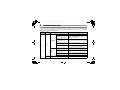
FR-A7NP
INSTRUCTION MANUAL
FR-A7NP
PROFIBUS-DP
communication function
PRE-OPERATION INSTRUCTIONS
1
INSTALLATION
2
WIRING
3
INVERTER SETTING
4
FUNCTIONS
5
PROFIBUS DEVICE DATA
6
PPO TYPE SUPPORT
7
PPO TYPE NON-SUPPORT
8
TROUBLESHOOTING
9
HEAD OFFICE: TOKYO BUILDING 2-7-3, MARUNOUCHI, CHIYODA-KU, TOKYO 100-8310, JAPAN
Printed in Japan
Specifications subject to change without notice.
INSTRUCTION MANUAL
IB(NA)-0600214ENG-C(1011) MEE
C
A7NP.book
1 ページ
2010年12月9日 木曜日 午前11時36分
Thank you for choosing this Mitsubishi Inverter plug-in option.
This Instruction Manual gives handling information and
precautions for use of this equipment. Incorrect handling might
cause an unexpected fault. Before using the equipment, please
read this manual carefully to use the equipment to its optimum.
Please forward this manual to the end user.
This section is specifically about
safety matters
Do not attempt to install, operate, maintain or inspect this
product until you have read through this Instruction Manual and
appended documents carefully and can use the equipment
correctly. Do not use this product until you have a full
knowledge of the equipment, safety information and
instructions.
In this Instruction Manual, the safety instruction levels are
classified into "WARNING" and "CAUTION".
WARNING
CAUTION
Incorrect
handling
may
cause
hazardous conditions, resulting in
death or severe injury.
Incorrect
handling
may
cause
hazardous conditions, resulting in
medium or slight injury, or may cause
only material damage.
CAUTION level may even lead to a serious
The
consequence according to conditions. Both instruction levels
must be followed because these are important to personal
safety.
SAFETY INSTRUCTIONS
1. Electric Shock Prevention
WARNING
• While power is ON or when the inverter is running, do not
open the front cover. You may get an electric shock.
• Do not run the inverter with the front cover or wiring cover
removed. Otherwise, you may access the exposed highvoltage terminals and charging part and get an electric shock.
• Even if power is OFF, do not remove the front cover except for
wiring or periodic inspection. You may accidentally touch the
charged inverter circuits and get an electric shock.
• Before wiring or inspection, power must be switched OFF. To
confirm that, LED indication of the operation panel must be
checked. (It must be OFF.) Any person who is involved in
wiring or inspection shall wait for at least 10 minutes after the
power supply has been switched OFF and check that there
are no residual voltage using a tester or the like. The
capacitor is charged with high voltage for some time after
power OFF, and it is dangerous.
• Any person who is involved in wiring or inspection of this
equipment shall be fully competent to do the work.
• The plug-in option must be installed before wiring. Otherwise,
you may get an electric shock or be injured.
• Do not touch the plug-in option or handle the cables with wet
hands. Otherwise you may get an electric shock.
• Do not subject the cables to scratches, excessive stress,
heavy loads or pinching. Otherwise you may get an electric
shock.
A-1
A7NP.book
2 ページ
2010年12月9日 木曜日 午前11時36分
2. Injury Prevention
3) Usage
WARNING
CAUTION
• The voltage applied to each terminal must be the ones
specified in the Instruction Manual. Otherwise burst, damage,
etc. may occur.
• The cables must be connected to the correct terminals.
Otherwise burst, damage, etc. may occur.
• Polarity must be correct. Otherwise burst, damage, etc. may
occur.
• While power is ON or for some time after power-OFF, do not
touch the inverter as they will be extremely hot. Doing so can
cause burns.
3. Additional Instructions
Also the following points must be noted to prevent an accidental
failure, injury, electric shock, etc.
1) Transportation and mounting
• Do not modify the equipment.
• Do not perform parts removal which is not instructed in this
manual. Doing so may lead to fault or damage of the inverter.
CAUTION
• When parameter clear or all parameter clear is performed, the
required parameters must be set again before starting operations
because all parameters return to the initial value.
• For prevention of damage due to static electricity, nearby
metal must be touched before touching this product to
eliminate static electricity from your body.
4) Maintenance, inspection and parts replacement
CAUTION
CAUTION
• Do not install or operate the plug-in option if it is damaged or
has parts missing.
• Do not stand or rest heavy objects on the product.
• The mounting orientation must be correct.
• Foreign conductive objects must be prevented from entering
the inverter. That includes screws and metal fragments or
other flammable substances such as oil.
2) Trial run
CAUTION
• Before starting operation, each parameter must be confirmed
and adjusted. A failure to do so may cause some machines to
make unexpected motions.
A-2
• Do not test the equipment with a megger (measure insulation
resistance).
5) Disposal
CAUTION
• This inverter plug-in option must be treated as industrial
waste.
6) General instruction
Many of the diagrams and drawings in this Instruction Manual
show the inverter without a cover or partially open for
explanation. Never operate the inverter in this manner. The
cover must be reinstalled and the instructions in the inverter
manual must be followed when operating the inverter.
A7NP.book
I ページ
2010年12月9日 木曜日 午前11時36分
⎯ CONTENTS ⎯
1
PRE-OPERATION INSTRUCTIONS
1.1
1.2
Inverter model ....................................................................................................................................1
Unpacking and product confirmation ..............................................................................................2
1.2.1
1.2.2
1.3
1.4
Product confirmation....................................................................................................................................... 3
Parts ............................................................................................................................................................... 4
Node address setting ........................................................................................................................5
Specifications.....................................................................................................................................6
1.4.1
1.4.2
2
Inverter option specifications .......................................................................................................................... 6
Communication specifications ........................................................................................................................ 6
INSTALLATION
2.1
2.2
2.3
3
4
17
Parameter list ...................................................................................................................................17
Operation mode setting...................................................................................................................18
4.2.1
4.2.2
4.3
11
Terminal block..................................................................................................................................11
Wiring................................................................................................................................................12
INVERTER SETTING
4.1
4.2
7
Pre-installation instructions .............................................................................................................7
Installation of the communication option LED display cover .......................................................8
Installation procedure .......................................................................................................................9
WIRING
3.1
3.2
1
Operation mode indicator ............................................................................................................................. 18
Operation mode switching and communication startup mode (Pr. 79, Pr. 340) ...........................................19
Start and speed command sources (Pr. 338, Pr. 339, Pr. 550) ....................................................22
I
A7NP.book
II ページ
4.3.1
4.4
5
Operation selection at communication error occurrence (Pr. 500 to Pr. 502) .............................................. 28
Fault and measures...................................................................................................................................... 32
Inverter reset ....................................................................................................................................34
FUNCTIONS
5.1
5.2
6
7
38
Device data (GSD file)......................................................................................................................38
Slave user parameter.......................................................................................................................42
PPO TYPE SUPPORT SPECIFICATION
7.1
7.2
7.3
7.4
7.5
7.6
7.7
36
Output from the inverter to the network ........................................................................................36
Input to the inverter from the network ...........................................................................................37
PROFIBUS DEVICE DATA
6.1
6.2
43
PROFIBUS profiles ..........................................................................................................................43
ID definitions ....................................................................................................................................44
Buffer memory map .........................................................................................................................45
Buffer memory configuration .........................................................................................................46
Buffer memory details .....................................................................................................................47
Outline of PNU..................................................................................................................................54
PROFIBUS PNU................................................................................................................................55
7.7.1
7.7.2
7.7.3
7.7.4
7.7.5
7.7.6
II
Communication EEPROM write selection (Pr. 342) .....................................................................................27
Operation at communication error occurrence ............................................................................28
4.4.1
4.4.2
4.5
2010年12月9日 木曜日 午前11時36分
Real-time monitor ......................................................................................................................................... 55
Parameter clear ............................................................................................................................................ 58
Operation mode read/write ........................................................................................................................... 58
Set frequency read ....................................................................................................................................... 58
Terminal input read....................................................................................................................................... 59
Inverter reset ................................................................................................................................................ 59
A7NP.book
III ページ
7.7.7
7.7.8
7.7.9
7.8
8
Node address read ....................................................................................................................................... 59
Fault records read ........................................................................................................................................ 60
PNU list read ................................................................................................................................................ 64
Standard parameters .......................................................................................................................65
PPO TYPE NON-SUPPORT SPECIFICATION
8.1
8.2
8.3
8.4
8.5
8.6
8.7
8.8
68
PROFIBUS profiles ..........................................................................................................................68
ID definitions ....................................................................................................................................69
Buffer memory map .........................................................................................................................69
Buffer memory configuration .........................................................................................................70
Buffer memory details .....................................................................................................................71
Outline of PNU..................................................................................................................................76
PROFIBUS PNU (module type A5NP).............................................................................................77
8.7.1
8.7.2
Real-time monitor area (IND=0000H (IND=00H, PP=00H)) ......................................................................... 77
System environment variable (sev) area (IND = 01PPH (IND = 01H, PP = 00H, 01H)) .............................. 79
Standard parameters .......................................................................................................................83
8.8.1
8.8.2
8.8.3
9
2010年12月9日 木曜日 午前11時36分
Normal parameter area (IND = 0200H (IND = 02H, PP = 00H)) .................................................................. 83
Pr. 900 to calibration parameter (frequency) area (IND=0300H (IND=03H, PP=00H))................................ 84
Pr. 900 to calibration parameter (%) area (IND=0400H (IND=04H, PP=00H)) ............................................ 85
TROUBLESHOOTING
86
III
A7NP.book
IV ページ
2010年12月9日 木曜日 午前11時36分
MEMO
IV
A7NP.book
1
1 ページ
2010年12月9日 木曜日 午前11時36分
PRE-OPERATION INSTRUCTIONS
1.1
Inverter model
The inverter model, 55K and 75K stated in this Instruction Manual differs according to -NA, -EC, -CH(T)
versions. Refer to the following correspondence table for each inverter model. (Refer to the instruction
manual of each inverter for the inverter model.)
For example, "for the 75K or higher" indicates "for the FR-A740-01440-NA or higher" in the case of FRA740 of NA version.
NA
F700
A700
A701
FR-F720(P)-55K
FR-F720(P)-75K
FR-F740(P)-55K
FR-F740(P)-75K
FR-A720-55K
FR-A720-75K
FR-A740-55K
FR-A740-75K
FR-A721-55K
FR-A741-55K
FR-F720-02330-NA
FR-F720-03160-NA
FR-F740-01160-NA
FR-F740-01800-NA
FR-A720-02150-NA
FR-A720-02880-NA
FR-A740-01100-NA
FR-A740-01440-NA
⎯
⎯
EC
⎯
⎯
FR-F740-01160-EC
FR-F740-01800-EC
⎯
⎯
FR-A740-01800-EC
FR-A740-02160-EC
⎯
⎯
CH
⎯
⎯
FR-F740-55K-CH(T)
FR-F740-S75K-CH(T)
⎯
⎯
FR-A740-55K-CHT
FR-A740-75K-CHT
⎯
⎯
1
1
A7NP.book
2 ページ
2010年12月9日 木曜日 午前11時36分
PRE-OPERATION INSTRUCTIONS
1.2
Unpacking and product confirmation
Take the plug-in option out of the package, check the product name, and confirm that the product is as you
ordered and intact.
This product is a plug-in option for the FR-A700/FR-F700P series inverter and the FR-F700 series inverter
assembled in and after December 2004.
Check the SERIAL number indicated on the rating plate or package.
z SERIAL number check
Refer to the inverter manual for the location of the rating plate.
Rating plate example
Symbol
4
Year
2
Month
{{{{{{
Control number
SERIAL (Serial No.)
The SERIAL consists of one symbol, two characters indicating production year and month,
and six characters indicating control number.
The last digit of the production year is indicated as the Year, and the Month is indicated by
1 to 9, X (October), Y (November), or Z (December).
2
A7NP.book
3 ページ
2010年12月9日 木曜日 午前11時36分
PRE-OPERATION INSTRUCTIONS
1.2.1
Product confirmation
Check the enclosed items.
Plug-in option
Mounting screw (M3 × 6mm) Hex-head screw for option
......................................... 1 ............ 2 (Refer to page 10.) mounting (5.5mm)
............. 1 (Refer to page 10.)
1
5.5mm
Communication option LED PROFIBUS® is a registered trademark of PROFIBUS User Organization.
display cover
.............. 1 (Refer to page 8.)
3
A7NP.book
4 ページ
2010年12月9日 木曜日 午前11時36分
PRE-OPERATION INSTRUCTIONS
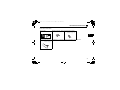
1.2.2
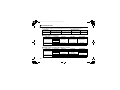
Parts
Switch for manufacturer setting
Do not change from
initially-set status (1, 2:OFF).
ON
1 2
Terminal block
Connect
the communication
cable. (Refer to page 11.)
Operation status indication LED
Lit/off of the LED indicate inverter operation status.
Mounting
hole
Front view
Rear view
LED1
STATUS
FR-A7NP
1 2
01
EF 2
01
EF 2
89
67 A
345
89
67 A
BCD
SW3
X16
BCD
SW2
ON
SW1
345
X1
Node address switch (Refer to page 5.)
Mounting hole
Connector
Mounting hole
Connect to the inverter option connector.
Mount on the inverter with an accessory mounting screw.
(Refer to page 8.)
Terminal
layout
Name
V+
D+
DD+
VFG
D+
DVDCNTR
FG
1 2
ON
01
EF 2
01
EF 2
89
67 A
89
67 A
BCD
SW3
345
BCD
SW2
345
Function
Set the inverter address within the range of 00H to
7DH.
OFF
Inverter power OFF
Operation status
A communication error with the master
Red is lit
indication LED
occurred
Green is lit During communication with the master
SW1
X16
4
Node address
switch
X1
A7NP.book
5 ページ
2010年12月9日 木曜日 午前11時36分
PRE-OPERATION INSTRUCTIONS
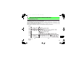
1.3 Node address setting
BCDE
BCDE
89
67 A
BCDE
F01
89
67 A
F01
45
23
89
67 A
X1
Node address 38 (26H):
Set the " ×" of X16(SW3) to "2" and the
"× " of X1(SW1) to "6".
45
23
89
67 A
X16
F01
45
23
F01
45
23
Node address 1:
Set the "× " of X16(SW3) to "0" and the
"× " of X1(SW1) to "1".
BCDE
•Setting with node address switch
Set the node address between "0H to 7DH" using node address switches on FR-A7NP (refer to page 3).
The setting is applied at the next power-ON.
Set the arrow (×) of the corresponding switches to a number or an alphabet to set a desired address.
•Setting example
X16
X1
CAUTION
BCDE
BCDE
89
67 A
5.
45
23
3.
4.
45
23
2.
Set the node address switch to the switch number (alphabet) position correctly.
Good
Bad
If the switch is set between numbers, normal data communication cannot be
example example
established.
F01
F01
Do not set the node addresses to 7EH through FFH. When these addresses are
set, they are recognized as 7DH.
The node addresses, 0H, 1H, 2H, 7CH, and 7DH, may not be available for some master modules.
You cannot set the same node address to other devices on the network. (Doing so disables proper
communication.)
Set the inverter node address before switching ON the inverter and do not change the setting while
power is ON. Otherwise you may get an electric shock.
89
67 A
1.
5
1
A7NP.book
6 ページ
2010年12月9日 木曜日 午前11時36分
PRE-OPERATION INSTRUCTIONS
1.4 Specifications
1.4.1
Inverter option specifications
Type
Inverter plug-in option type
Number of nodes occupied One inverter occupies one node.
Connection cable
Cable which supports 12.0Mbps communication (EIA-485(RS-485) standard)
1.4.2
Communication specifications
Communication speed
6
Wiring length 1200m or less
Wiring length 600m or less
Wiring length 200m or less
Wiring length 100m or less
9600bps, 19.2Kbps, 93.75Kbps
187.5Kbps
500Kbps, 1.5Mbps
3.0Mbps, 6.0Mbps, 12.0Mbps
A7NP.book
2
7 ページ
2010年12月9日 木曜日 午前11時36分
INSTALLATION
2.1
Pre-installation instructions
Make sure that the input power of the inverter is OFF.
CAUTION
With input power ON, do not install or remove the plug-in option. Otherwise, the inverter and
plug-in option may be damaged.
For prevention of damage due to static electricity, touch nearby metal before touching this
product to eliminate static electricity from your body.
2
7
A7NP.book
8 ページ
2010年12月9日 木曜日 午前11時36分
INSTALLATION
2.2
Installation of the communication option LED display cover
Mount the cover for displaying the operation status indication LED for the communication option on the
inverter front cover.
1)Cut off hooks on the rear of the inverter front
cover with nipper, etc. and open a window for
fitting the LED display cover.
2)Fit the communication option LED display
cover to the front of the inverter front cover
and push it into until fixed with hooks.
Cut off with a nipper, etc.
Fit it so that the position of
lenses is in the upper-right
of the LED display cover.
When fitted
Cut off with a nipper, etc.
CAUTION
Take care not to hurt your hand and such with portions left by cutting hooks of the rear of the
front cover.
8
A7NP.book
9 ページ
2010年12月9日 木曜日 午前11時36分
INSTALLATION
2.3
Installation procedure
1) Remove the inverter front cover.
1)
2) Mount the hex-head screw for option
mounting into the inverter screw hole
(on earth plate). (size 5.5mm,
tightening torque 0.56Nxm to 0.75Nxm)
Screw hole for
option mounting
Inverter side
option
connector
9
78
4
78
01
56
23
01
4
56
Hex-head screw
for option mounting
23
9
Screw hole for
option mounting
(on earth plate)
3)
2)
4) Mounting
3) Securely fit the connector of the plug-in
option to the inverter connector along
the guides.
4) Securely fix the both right and left sides
of the plug-in option to the inverter with
the accessory mounting screws.
(Tightening torque 0.45Nxm to
0.55Nxm)
If the screw holes do not line-up, the
connector may not have been plugged
securely. Check for loose plugging.
screws
REMARKS
• Remove a plug-in option after removing two screws on both left and right sides.
(The plug-in option is easily removed if the control circuit terminal block is removed before.)
9
2
A7NP.book
10 ページ
2010年12月9日 木曜日 午前11時36分
INSTALLATION
CAUTION
•
When using this option unit with the FR-A700 series inverter, mount it in the
"option connector 3 (lowermost connector)" of the inverter.
If it is fitted in option connector 1 or 2, "
" or "
" (option fault) is
displayed and the inverter will not operate. In addition, when the inverter cannot
recognize that the option is mounted due to improper installation, etc.,
•
•
•
Mounting
Position
Fault
Display
Connector 1
Connector 2
"
" (option fault) is displayed even if the option is fitted in the option
Connector 3
connector 3.
The FR-F700(P) series has one connection connector for the plug-in option. When the inverter cannot
recognize that the option unit is mounted due to improper installation, etc., "
" (option fault) is
displayed.
Take caution not to drop a hex-head screw for option mounting or mounting screw during mounting and
removal.
Pull out the option straight to remove. Otherwise, the connector may be damaged.
10
A7NP.book
3
11 ページ
2010年12月9日 木曜日 午前11時36分
WIRING
3.1 Terminal block
Terminal block layout
B
1
2
3
4
5
6
D+
DVDCNTR
FG
V+
D+
DD+
VFG
A
1
2
3
4
5
6
Terminal
Terminal Name
Definition
No.
Voltage output (approx. 5V to V-)
1-A
V+ (VP) *1
1-B
D+ (RXD/TXD-P) Sends and receives PROFIBUS signal+ (B-line)
2-A
D+ (RXD/TXD-P) Sends and receives PROFIBUS signal+ (B-line)
2-B
D+ (RXD/TXD-N) Sends and receives PROFIBUS signal- (A-line)
3-A
D+ (RXD/TXD-N) Sends and receives PROFIBUS signal- (A-line)
3-B
V- (DGND) *1
GND of D+/D4-A
D+ (RXD/TXD-P) *1 (To connect a terminating resistor)
4-B
D+ (RXD/TXD-N) *1 (To connect a terminating resistor)
5-A
V- (DGND) *1
GND of D+/D5-B
CNTR *2
Control signal (sending request from the inverter)
6-A
FG
(Connected to the earth of the inverter unit)
6-B
FG
(Connected to the earth of the inverter unit)
*1 Use this when connecting a terminating resistor.
*2 It may not be necessary depending on the master used.
11
3
A7NP.book
12 ページ
2010年12月9日 木曜日 午前11時36分
WIRING
3.2 Wiring
Use the network connection cable which supports 12.0Mbps communication.
(1) Strip off the sheath of the PROFIBUS communication dedicated cable and wind wires and shield cables
to use. If the length of the sheath pealed is too long, a short circuit may occur among neighboring wires.
If the length is too short, cables and shield cables might come off.
Cable stripping length
Approx 5mm
Wire the stripped cable after twisting it to prevent it from
becoming loose.
In addition, do not solder it.
Use a blade terminal as required.
REMARKS
yInformation on blade terminals...recommended product (as of January 2010)
Terminal Screw Size
M2
Cable Size
(mm2)
0.3 to 0.5
Blade Terminal Model
With insulation
Without insulation
sleeve
sleeve
Al 0,5-6WH
Blade terminal crimping tool: CRIMPFOX 6 (Phoenix Contact Co., Ltd.)
When using the blade terminal (without insulation sleeve),
use care so that the twisted wires do not come out.
12
A 0,5-6
Manufacturer
Phoenix Contact
Co.,Ltd.
A7NP.book
13 ページ
2010年12月9日 木曜日 午前11時36分
WIRING
(2) Loosen the terminal screw and insert the cable into the terminal.
Tighten each cable with fixing screws to the recommended tightening torque.
<Cable connection example>
<Connection example of multiple inverters>
To next inverter
D+ DV-
D+ D-
D+ DV-
V-
To master
Screw Size
Tightening Torque
Cable Size
Screwdriver
M2
0.22N•m to 0.25N•m
0.3mm2 to 0.75mm2
Small
flat-blade screwdriver
(Tip thickness: 0.4mm /tip width: 2.5mm)
CAUTION
Undertightening can cause cable disconnection or malfunction. Overtightening can cause a short circuit or
malfunction due to damage to the screw or unit.
13
3
A7NP.book
14 ページ
2010年12月9日 木曜日 午前11時36分
WIRING
(3) Terminating resistor
Connect terminating resistors to the both ends of a network if the both ends are FR-A7NP-mounted
inverters.
Connection example
Master station
Inverter
Inverter
PLC etc.
Terminating
resistor
Terminating
resistor
Power
supply
Motor Power
supply
Motor
PROFIBUS communication cable
R1=390Ω
R2=220Ω
R3=390Ω
2% 1/4W
2% 1/4W
2% 1/4W
To other inverter
(node)
14
R1
R2
V+
D+
DD+
VFG
D+
DVD- CNTR FG
R3
A7NP.book
15 ページ
2010年12月9日 木曜日 午前11時36分
WIRING
9
78
4
23
9
01
23
4
78
9
78
78
56
4
56
23
01
56
01
4
01
Cut off
with a
nipper,
etc.
23
9
(4) For wiring of the inverter which has one front cover, route wires between the control circuit terminal
block and front cover. If cables cannot be routed between the control circuit terminal block and front
cover (approx. 7mm), remove a hook of the front cover, and use the space became available.
For wiring of the inverter which has front cover 1 and 2, use the space on the left side of the control
circuit terminal block.
56
Front cover
Cut off a hook on the inverter
front cover side surface.
(Cut off so that no portion is left.)
Inverter which has one front cover
Front cover 1
Front cover 2
Control circuit
terminal block
Inverter which has front cover 1 and 2
* The inverter models of 22K and 30K of the FR-A700 series, 30K and 37K of the FR-F700 series in -NA, -EC versions are as
follows.
A700
F700
FR-A720-22K
FR-A740-22K
FR-A720-30K
FR-A740-30K
FR-F720(P)-30K
FR-F740(P)-30K
FR-F720(P)-37K
FR-F740(P)-37K
NA
EC
FR-A720-00900-NA
FR-A740-00440-NA
FR-A720-01150-NA
FR-A740-00570-NA
FR-F720-01250-NA
FR-F740-00620-NA
FR-F720-01540-NA
FR-F740-00770-NA
⎯
FR-A740-00620-EC
⎯
FR-A740-00770-EC
⎯
FR-F740-00620-EC
⎯
FR-F740-00770-EC
15
3
A7NP.book
16 ページ
2010年12月9日 木曜日 午前11時36分
WIRING
REMARKS
⋅ When the hook of the inverter front cover is cut off for wiring, the protective structure (JEM1030) changes to open
type (IP00).
CAUTION
When performing wiring using the space between the inverter front cover and control circuit
terminal block, take care not to subject the cable to stress.
After wiring, wire offcuts must not be left in the inverter. They may cause an error, failure or
malfunction.
16
A7NP.book
4
17 ページ
2010年12月9日 木曜日 午前11時36分
INVERTER SETTING
4.1 Parameter list
The following parameters are used for the communication option (FR-A7NP).
Set the values according to need.
Parameter
Number
79
338
339
340
342
349*1
500*1
501*1
502*1
550
*1
Name
Setting Range
Minimum
Setting
Increments
Initial
Value
Refer to page
Operation mode selection
Communication operation
command source
Communication speed
command source
Communication startup mode
selection
Communication EEPROM write
selection
Communication reset selection
Communication error execution
waiting time
Communication error
occurrence count display
Stop mode selection at
communication error
NET mode control source
selection
0 to 4, 6, 7
1
0
22
0, 1
1
0
25
0, 1, 2
1
0
25
0, 1, 2, 10, 12
1
0
22
0, 1
1
0
30
0, 1
1
0
38
0 to 999.8s
0.1s
0
31
0
1
0
32
0, 1, 2, 3
1
0
33
0, 1, 9999
1
9999
25
4
Parameters which can be displayed when the plug-in option (FR-A7NP) is mounted.
17
A7NP.book
18 ページ
2010年12月9日 木曜日 午前11時36分
INVERTER SETTING
4.2
Operation mode setting
The inverter mounted with a communication option has three operation modes.
(1) PU operation [PU].............. Controls the inverter from the keys of the operation panel on the inverter or
parameter unit (FR-DU07/FR-PU07).
(2) External operation [EXT] ... Controls the inverter by switching ON/OFF external signals connected to
the control circuit terminals of the inverter.
(The inverter is factory-set to this mode.)
(3) Network operation [NET] ... Controls the inverter with instructions from the network via the
communication option.
(The operation signal and running frequency can be entered from the
control circuit terminals depending on the Pr. 338 Communication operation
command source and Pr. 339 Communication speed command source settings.
Refer to page 23.)
4.2.1
Operation mode indicator
FR-DU07
Operation mode indicators
(The inverter operates according to the LED lit mode.)
PU: PU operation mode
EXT: External operation mode
NET: Network operation mode
18
A7NP.book
19 ページ
2010年12月9日 木曜日 午前11時36分
INVERTER SETTING
4.2.2
Operation mode switching and communication startup mode (Pr. 79, Pr. 340)
(1) Operation mode switching conditions
Before switching the operation mode, check that:
1) The inverter is at a stop;
2) Both the STF and STR signals are OFF; and
3) The Pr. 79 Operation mode selection setting is correct.
(Set with the operation panel of the inverter.)
Refer to the Inverter Manual for details of Pr. 79.
(2) Operation mode selection at power ON and at restoration from instantaneous power
failure
The operation mode at power ON and at restoration from instantaneous power failure can be selected.
Set a value other than "0" in Pr. 340 to select the Network operation mode.
After started in Network operation mode, parameter write from the network is enabled.
REMARKS
1. Change of the Pr. 340 setting is applied at power ON or an inverter reset.
2. Pr. 340 can be changed with the operation panel in any operation mode.
19
4
A7NP.book
20 ページ
2010年12月9日 木曜日 午前11時36分
INVERTER SETTING
Pr. 340
Setting
Pr. 79
Setting
Operation Mode at Power ON or Power
Restoration
Operation Mode Switchover
0 (initial
value)
1
Switching among the External, PU, and NET operation mode is
External operation mode
enabled *1
PU operation mode
PU operation mode fixed
Switching between the External and NET operation mode is enabled
2
External operation mode
0
Switching to the PU operation mode is disallowed
3, 4
External/PU combined operation mode
Operation mode switching is disallowed
(initial
Switching among the External, PU, and NET operation mode is
value)
6
External operation mode
enabled while running.
X12 (MRS) signal ON ..... External operation mode Switching among the External, PU, and NET operation mode is enabled *1
7
X12 (MRS) signal OFF ... External operation mode External operation mode fixed (Forcibly switched to External
operation mode.)
0
NET operation mode
1
PU operation mode
2
NET operation mode
3, 4
External/PU combined operation mode
Same as when Pr. 340 = "0"
1, 2 *2
NET operation mode
6 *4
X12 (MRS) signal ON .... NET operation mode
7
X12 (MRS) signal OFF ... External operation mode
0
NET operation mode
Switching between the PU and NET operation mode is enabled *3
1
PU operation mode
Same as when Pr. 340 = "0"
2
NET operation mode
NET operation mode fixed
10, 12 *2
3, 4
External/PU combined operation mode
Same as when Pr. 340 = "0"
6 *4
NET operation mode
Switching between the PU and NET operation mode is enabled while running *3
7
External operation mode
Same as when Pr. 340 = "0"
*1 Operation mode cannot be directly changed between the PU operation mode and Network operation mode.
*2 The Pr. 340 settings "2, 12" are mainly used for communication operation using the inverter RS-485 terminal.
When a value other than "9999" (selection of automatic restart after instantaneous power failure) is set in Pr. 57 Restart coasting time, the
inverter will resume the same operation state which was in before after power has been restored from an instantaneous power failure.
When Pr.340 = "1, 10", a start command turns OFF if power failure has occurred and then restored during a start command is ON.
*3 Operation mode can be changed between the PU operation mode and Network operation mode with
of the operation panel
(FR-DU07) and X65 signal.
*4 Pr. 79 = "6" and Pr. 128 to Pr. 134 (PID control) are not activated simultaneously. Switchover mode and PID control are made invalid, and
the inverter performs the same operation as when "0" is set in Pr. 79.
20
A7NP.book
21 ページ
2010年12月9日 木曜日 午前11時36分
INVERTER SETTING
(3) Operation mode switching method
When "0, 1, or 2" is set in Pr. 340
External operation
Switching from the PU
Switching from the network
Switch to the External
operation mode from
the network.
Press
Switch to the Network operation
mode from the network.
Press
the PU to light
Network operation
When "10 or 12" is set in Pr. 340
PU to light
of
of the
.
.
PU operation
4
Press of of the PU to light
.
Network operation
PU operation
Press of of the PU to light
.
For the switching method from the external terminal, refer to the Inverter Manual.
Refer to page 58 and 81 for a switching method from the network.
CAUTION
⋅ When starting the inverter in the Network operation mode at power ON or an inverter reset, set a value other than
"0" in Pr. 340. (Refer to page 19)
⋅ When setting a value other than "0" in Pr. 340, make sure that the initial settings of the inverter are correct.
21
A7NP.book
22 ページ
2010年12月9日 木曜日 午前11時36分
INVERTER SETTING
4.3
Start and speed command sources (Pr. 338, Pr. 339, Pr. 550)
(1) Select command source for the Network operation mode (Pr. 550)
A control location for the Network operation mode can be selected from either the inverter RS-485
terminals or a communication option.
When using a communication option, set "0 or 9999 (initial value)" in Pr. 550.
Parameter
Number
Name
Initial Value
Setting
Range
0
1
550
NET mode operation
command source selection
9999
9999
Refer to the Inverter Manual for details.
22
Description
Command source is at a
communication option
(Command source is not at inverter
RS-485 terminals)
Command source is at inverter RS485 terminals
(Command source is not at a
communication option)
Automatic recognition of the
communication option
Normally, command source is at RS485 terminals. When a
communication option is mounted,
the command source is at a
communication option.
A7NP.book
23 ページ
2010年12月9日 木曜日 午前11時36分
INVERTER SETTING
(2) Selection of command source for the Network operation mode (Pr. 338, Pr. 339)
⋅ There are two command types: the start command, which controls the signals related to the inverter
start command and function selection, and the speed command, which controls signals related to
frequency setting.
⋅ In Network operation mode, commands from the external terminals and communication are as listed
below.
Control
Location
Selection
Fixed
functions
(Functions
equivalent
to
terminals)
7
8
REX 15-speed selection
Pr. 178 to Pr. 189 settings
1
2
3
4
5
6
0:NET
9
X9 Third function *1
10 X10 Inverter run enable signal
1:External
1:
2:
1:
2:
0:NET External External 0:NET External External
NET
⎯
NET
NET
⎯
NET
⎯
External
⎯
⎯
External
⎯
⎯
External
⎯
External
Terminal 1
operation command/
RL Low-speed
remote setting clear
Middle-speed operation command/
RM remote setting deceleration
RH High-speed operation command/
remote setting acceleration
RT Second function selection
AU Terminal 4 input selection
JOG Jog operation selection
Automatic restart after
CS instantaneous power failure
selection
OH External thermal relay input
0
Selective functions
Pr. 338 Communication operation
command source
Pr. 339 Communication speed
command source
Running frequency from communication
Terminal 2
Terminal 4
Remarks
Compensation
NET
External
NET
External
NET
External
NET
External
External
NET
NET
⎯
NET
Combined
⎯
⎯
External
Pr. 59 = "0"
(multi-speed)
Pr. 59 = "1, 2"
(remote)
External
Combined
External
External
External
NET
External
NET
NET
External
Pr. 59 = "0"
(multi-speed)
External
External
23
4
A7NP.book
24 ページ
2010年12月9日 木曜日 午前11時36分
INVERTER SETTING
Control
Location
Selection
11 X11
12 X12
13 X13
14 X14
15 BRI
16 X16
Pr. 178 to Pr. 189 settings
Selective functions
17 X17
18 X18
19 X19 *1
20 X20 S-pattern acceleration/deceleration
C switching terminal *1
22 X22 Orientation command *1, *2
23 LX Pre-excitation *1
Output stop
24 MRS
25
26
27
28
37
42
43
44
24
Pr. 338 Communication operation
command source
Pr. 339 Communication speed
command source
FR-HC connection, instantaneous
power failure detection
PU operation external interlock
External DC injection brake
operation is started *3
PID control valid terminal
Brake opening completion signal *1
PU-External operation switchover
Load pattern selection forward
rotation reverse rotation boost *1
V/F switchover *1
Load torque high speed frequency
STOP
MC
TL
X28
X37
X42
X43
X44
0:NET
Remarks
External
External
NET
NET
External
NET
External
NET
External
External
External
NET
External
NET
External
NET
External
NET
External
NET
NET
Combined
External
External
External
PU operation interlock
Start self-holding selection
Control mode switchover *1
Torque limit selection *1
Start time tuning *1
Traverse function selection *4
Torque bias selection 1 *1, *2
Torque bias selection 2 *1, *2
P/PI control switchover *1
1:External
1:
2:
1:
2:
0:NET
0:NET
External External
External External
External
⎯
NET
NET
NET
NET
NET
NET
NET
External
External
External
External
External
External
External
External
Pr. 79 ≠ "7"
Pr. 79 = "7"
When the X12 signal
is not assigned
A7NP.book
25 ページ
2010年12月9日 木曜日 午前11時36分
INVERTER SETTING
Pr. 338 Communication operation
command source
Pr. 339 Communication speed
command source
Control
Location
Selection
Pr. 178 to Pr. 189 settings
Selective functions
50
60
61
62
63
SQ Sequence start *5
STF
STR
RES
PTC
64 X64
65 X65
66 X66
67 X67
68
NP
69 CLR
70 X70
71 X71
74 X74
*1
*2
*3
*4
*5
Forward rotation command
Reverse rotation command
Reset
PTC thermistor selection
PID forward rotation action
switchover
PU/NET operation switchover
External/NET operation switchover
Command source switchover
Conditional position pulse train
sign *1, *2
Conditional position droop pulse
clear *1, *2
DC feeding operation permission *1
DC feeding cancel *1
Magnetic flux decay output shutoff
signal
0:NET
1:External
1:
2:
1:
2:
0:NET
0:NET
External External
External External
External and NET*
External
NET
NET
External
External
Remarks
* The signal is valid
when there are
inputs from external
terminals and NET.
External
External
NET
External
NET
External
External
External
External
4
External
External
NET
NET
External
External
NET
External
Setting can be made only for the FR-A700 series.
Available only when used with the FR-A7AP.
For the FR-F700 series, setting can be made only for the EC and NA versions.
Setting can be made only for the EC and CH versions.
Setting can be made only for the FR-A700 series NA and EC versions.
25
A7NP.book
26 ページ
2010年12月9日 木曜日 午前11時36分
INVERTER SETTING
[Explanation of table]
External
:Control by signal from external terminal is only valid.
NET
:Control from network is only valid
Combined
:Operation from either external terminal or communication is valid.
⎯
:Operation from either external terminal or computer is invalid.
Compensation :Control by signal from external terminal is only valid if Pr. 28 Multi-speed input compensation setting is "1".
REMARKS
The Pr. 338 and Pr. 339 settings can be changed while the inverter is running when Pr. 77 = 2. Note that the setting
change is applied after the inverter has stopped. Until the inverter has stopped, communication operation command
source and communication speed command source before the setting change are valid.
26
A7NP.book
27 ページ
2010年12月9日 木曜日 午前11時36分
INVERTER SETTING
4.3.1
Communication EEPROM write selection (Pr. 342)
When parameter write is performed from the communication option, write to RAM is enabled. Set when
frequent parameter changes are necessary.
Parameter
Number
342
Name
Communication EEPROM write
selection
Initial
Value
Setting
Range
0
0
1
Description
Parameter values written by
communication are written to the
EEPROM and RAM.
Parameter values written by
communication are written to the RAM.
⋅ When changing the parameter values frequently, set "1" in Pr. 342 to write them to the RAM.
Performing frequent parameter write with "0 (initial value)" (EEPROM write) set will shorten the life of the
EEPROM.
REMARKS
When "1" (write to RAM only) is set in Pr. 342, powering OFF the inverter will erase the changed parameter values.
Therefore, the parameter values available when power is switched ON again are the values stored in EEPROM
previously.
27
4
A7NP.book
28 ページ
2010年12月9日 木曜日 午前11時36分
INVERTER SETTING
4.4
Operation at communication error occurrence
4.4.1
Operation selection at communication error occurrence (Pr. 500 to Pr. 502)
You can select operations at communication error occurrences by setting Pr. 500 to Pr. 502 under network operation.
(1) Waiting time for the communication line error output after a communication error
Waiting time for the communication error output after a communication line error occurrence can be
set.
Parameter
Number
Name
Setting Range
Minimum Setting
Increments
Initial Value
500
Communication error
execution waiting time
0 to 999.8s
0.1s
0
Communication line status
Communication error
(E.OP1, E.OP3)
Alarm signal(LF)
(Pr. 502 = 3)
Normal
Error
Normal
Error
Recognition
Pr. 500
setting time
Pr. 500
setting time
ON
When a communication line error occurs and lasts longer than the time set in Pr. 500, it is recognized
as a communication error.
If the communication returns to normal within the time, it is not recognized as a communication error,
and the operation continues.
28
A7NP.book
29 ページ
2010年12月9日 木曜日 午前11時36分
INVERTER SETTING
(2) Displaying and clearing the communication error count
The cumulative count of communication error occurrences can be displayed.
Write "0" to clear this cumulative count.
Parameter
Number
Name
Setting Range
Minimum Setting
Increments
Initial Value
501
Communication error
occurrence count display
0
1
0
Count timing depending on
communication line status
Normal
Error
Normal
Incremented by 1
Error
Incremented by 1
At the point of communication line error occurrence, Pr. 501 Communication error occurrence count
display is incremented by 1.
4
CAUTION
Communication error count is temporarily stored in the RAM. The error count is stored in EEPROM only once
per hour. If power reset or converter reset is performed, Pr. 501 setting will be the one that is last stored to
EEPROM depending on the reset timing.
29
A7NP.book
30 ページ
2010年12月9日 木曜日 午前11時36分
INVERTER SETTING
(3) Inverter operation at a communication error occurrence
How the inverter operates at a communication line error or an option unit fault can be set.
Parameter
Number
Name
Setting Range
Minimum Setting
Increments
Initial Value
502
Stop mode selection at
communication error
0, 1, 2, 3
1
0
About setting
zOperation at an error occurrence
Fault record
Communication line
Communication
option itself
Pr. 502 Setting
0
1
2
3
0, 3
1, 2
Operation
Indication
Fault Output
Continued *
Normal indication *
Not provided *
Coast to stop
Decelerated to stop
E. 1 or E. 3 lit
E. 1 or E. 3 lit after stop
Provided
Provided after stop
* When the communication returns to normal within the time period set in Pr. 500, the communication option error (E.OP1 or
E.OP3) does not occur.
zOperation at error recognition after elapse of Pr. 500 time
Fault record
Communication line
Communication
option itself
30
Pr. 502 Setting
Operation
Indication
Fault Output
0
1
2
3
0, 3
1, 2
Coast to stop
E.OP1 or E.OP3 lit
Decelerated to stop
E.OP1 or E.OP3 lit
after stop
Provided
Provided after stop
Continued
Coast to stop
Decelerated to stop
Normal indication
E. 1 or E.3 lit
E. 1 or E.3 lit after stop
Not provided
Provided
Provided after stop
A7NP.book
31 ページ
2010年12月9日 木曜日 午前11時36分
INVERTER SETTING
zOperation at error removal
Fault record
Pr. 502 Setting
Communication line
0
1
2
3
Communication
option itself
0, 3
1, 2
Operation
Indication
Fault Output
Kept stopped
E.OP1 or E.OP3 kept lit
Kept provided
Restart
Continued
Normal indication
Not provided
Kept stopped
E. 1 or E.3 kept lit
Kept provided
CAUTION
1.
2.
3.
4.
5.
6.
7.
Communication line error [E.OP1 (fault data: HA1) or E.OP3 (fault data: HA3)] is an error that occurs on
the communication line. Communication option error [E. 1 (fault data: HF1) or E. 3 (fault data: HF3)] is an
error that occurs in the communication circuit inside the option.
Fault output indicates the fault output signal (ALM signal) and fault bit output.
When the fault output setting is active, fault records are stored in the faults history.
When the fault output setting is not active, fault record is overwritten to the faults history temporarily but
not stored.
After the error is removed, the fault indication is reset, changing the display back to normal, and the last
fault is displayed in the faults history.
When the Pr. 502 setting is "1" or "2", the deceleration time is the normal deceleration time setting
(e.g. Pr. 8, Pr. 44, Pr. 45).
The acceleration time at a restart is the normal acceleration time setting (e.g. Pr. 7, Pr. 44).
When the Pr. 502 setting is "2", the operation/speed command at a restart is the one given before the error
occurrence.
When a communication line error occurs at the Pr. 502 setting of "2", removing the error during deceleration
causes acceleration to restart at that point. (Acceleration is not restarted if the error is that of the option unit itself.)
31
4
A7NP.book
32 ページ
2010年12月9日 木曜日 午前11時36分
INVERTER SETTING
4.4.2
Fault and measures
(1) The inverter operates as follows at fault occurrences.
Fault
Location
Inverter
Status
Inverter operation
Data communication
Communication Inverter operation
line
Data communication
Communication Inverter
operation
option
connection
Data
error
communication
Communication
option
Inverter
Error of
operation
communication
Data
option itself
communication
32
Network
Operation
Inverter trip
Continued
Inverter trip
(depends on
the Pr. 502 setting)
Stop
Inverter trip
(depends on
the Pr. 502 setting)
Operation Mode
External
Operation
PU Operation
Inverter trip
Continued
Inverter trip
Continued
Continued
Continued
Stop
Inverter trip
(depends on
the Pr. 502 setting)
Stop
Inverter trip
(depends on
the Pr. 502 setting)
Continued
Continued
Continued
Inverter trip
(depends on
the Pr. 502 setting)
Continued
Continued
Stop
Stop
Stop
A7NP.book
33 ページ
2010年12月9日 木曜日 午前11時36分
INVERTER SETTING
(2) Measures at error occurrences
Fault Indication
E.OP1, E.OP3
E.1, E.2, E.3
Error Definition
Communication line
error
Option fault
Measures
Check the LED status of the option unit and remove the cause of the
alarm. (Refer to page 3 for LED indication status)
Check the other nodes on the network.
Inspect the master.
Check the connection between the inverter and option unit for poor
contact, etc. and remove the cause of the error.
For the FR-A700 series, fit the communication option in the option
connector 3.
When faults other than the above are displayed, refer to the inverter manual and remove the cause of the error.
4
33
A7NP.book
34 ページ
2010年12月9日 木曜日 午前11時36分
INVERTER SETTING
4.5
Inverter reset
(1) Operation conditions of inverter reset
Which resetting method is allowed or not allowed in each operation mode is described below.
Resetting Method
Network
Operation
Allowed
Operation Mode
External
PU
Operation
Operation
Disallowed
Disallowed
Allowed
Allowed
Disallowed
Disallowed
Enabled
Enabled
Enabled
Enabled
Enabled
Enabled
Enabled
Enabled
Inverter reset (Refer to page 59) *1
Reset from the
Error reset (STW(bit7))at inverter fault Pr.349 = 0
network
Allowed
(Refer to page 49) *2
Pr.349 = 1
Turn ON the inverter terminal RES (RES signal)
Enabled
Switch OFF inverter power
Enabled
Enabled
Reset from the Inverter reset
PU/DU
Reset at inverter fault
Enabled
*1 Inverter reset can be made any time.
*2 Reset can be made only when the protective function of the inverter is activated. (Available with PPO type 1 to 5 only)
CAUTION
1.
2.
3.
34
When a communication line error has occurred, reset cannot be made from the network.
The inverter is set to the External operation mode if it has been reset in Network operation mode in the
initial status.
To resume the network operation, the inverter must be switched to the Network operation mode again.
Set a value other than "0" in Pr. 340 to start in the Network operation mode. (Refer to page 19.)
The inverter cannot be controlled for about 1s after release of a reset command .
A7NP.book
35 ページ
2010年12月9日 木曜日 午前11時36分
INVERTER SETTING
(2) Error reset operation selection at inverter fault
When used with the communication option (FR-A7NP), an error reset command* from network can be
invalid in the External operation mode or PU operation mode.
Parameter
Number
349
Name
Communication reset
selection
Initial
Value
Setting
Range
0
0
1
Function
Error reset* is enabled independently of
operation mode
Error reset* is enabled only in the Network
operation mode
* An error reset command (STW (bit7)) at inverter fault is available with PPO type 1 to 5. (Refer to page 49.)
4
35
A7NP.book
5
36 ページ
2010年12月9日 木曜日 午前11時36分
FUNCTIONS
5.1 Output from the inverter to the network
Main items to be output from the inverter (FR-A7NP) to the network and their descriptions are explained
below.
Item
Inverter monitor
Parameter read
Inverter status
Operation mode read
Set frequency read
Terminal input read
Node address read
Alarm definition read
PNU list read
Description
Monitor various items such as inverter output frequency
and output current.
Read parameter settings of the inverter.
Monitor output signal of the inverter.
Read the operation mode of the inverter.
Read the frequency set in the inverter.
Read the analog value of terminal 2, 4, 1.
Read node address of the inverter.
Monitor alarm history occurred in the inverter and
energization time, output frequency, output current and
output voltage at alarm occurrence are monitored.
Read the available PNU number.
Refer to Page
PPO Type
PPO Type
Support
Non-Support
Specification Specification
51, 55
77
47, 65
50
50, 58
58
59
59
71, 83
74
⎯
81
81
⎯
60
82
64
⎯
REMARKS
Refer to the inverter manual for functions controllable from the network in each operation mode.
36
A7NP.book
37 ページ
2010年12月9日 木曜日 午前11時36分
FUNCTIONS
5.2 Input to the inverter from the network
Main items which can be commanded from the network to the inverter and their descriptions are explained
below.
Item
Frequency setting
Operation mode write
Description
Set the running frequency of the inverter.
Set the operation mode of the inverter.
Set the control input command such as forward operation
Run command
signal (STF) and reverse rotation signal (STR).
Inverter reset
Reset the inverter.
Parameter write
Set parameters of the inverter.
Parameter clear
Return parameters to the initial values.
Input terminal function Use the function of the inverter input terminal.
Refer to page
PPO Type
PPO Type
Support
Non-Support
Specifications Specifications
51
58
81
81
49
80
49, 59
47, 65
58
52
79
71, 83
79
80
5
REMARKS
Refer to the inverter manual for functions controllable from the network in each operation mode.
37
A7NP.book
6
38 ページ
2010年12月9日 木曜日 午前11時36分
PROFIBUS DEVICE DATA
6.1 Device data (GSD file)
melc08fa.gsd is a GSD file designed to recognize the features and functions of the PROFIBUS-DP devices
of the FR-A7NP. You can obtain it from us.
GSD file can be downloaded from Mitsubishi Electric FA Network Service
MELFANS web: http://www.MitsubishiElectric.co.jp/melfansweb or obtained from your sales representative.
When editing this file, use a text editor.
For installation instructions, refer to the instruction manual of the PROFIBUS-DP Configuration Software.
Although this product complies with PPO type specification, it includes specifications which do not support
PPO type specification (FR-A5NP intercompatibility protocol). This manual states the section supporting
PPO type specification as PPO type support specification and the section not supporting PPO type as PPO
type non-support specification.
CAUTION
You cannot use the device data which does not include PPO supporting specification (data for the FR-A5NP).
<melc08fa.gsd>
Parameter
#Profibus_DP
GSD_Revision
Vendor_Name
Model_Name
Revision
Ident_Number
Protocol_Ident
Station_Type
FMS_Supp
38
Value
1
"Mitsubishi Electric"
"FR-A7NP"
"Revision 1.00"
08FAH
0
0
0
Description *1
File header
ID version of GSD file
Manufacturer name *2
Product name
Product version
Device number obtained from Profibus Nutzer Organization
PROFIBUS-DP is 0 fixed.
DP slave is 0 fixed.
FMS (Field-Bus Message Specifications) not supported.
A7NP.book
39 ページ
2010年12月9日 木曜日 午前11時36分
PROFIBUS DEVICE DATA
Parameter
Value
Hardware_Release
Software_Release
9.6_supp
19.2_supp
93.75_supp
187.5_supp
500_supp
1.5M_supp
3M_supp
6M_supp
12M_supp
MaxTsdr_9.6
MaxTsdr_19.2
"BC101B376"
"7732"
1
1
1
1
1
1
1
1
1
15
15
MaxTsdr_93.75
15
MaxTsdr_187.5
15
MaxTsdr_500
MaxTsdr_1.5M
MaxTsdr_3M
MaxTsdr_6M
15
25
50
100
MaxTsdr_12M
200
Description *1
Hardware version
Software version
Communication speed 9600bps support
Communication speed 19.2Kbps support
Communication speed 93.75Kbps support
Communication speed 187.5Kbps support
Communication speed 500Kbps support
Communication speed 1.5Mbps support
Communication speed 3.0Mbps support
Communication speed 6.0Mbps support
Communication speed 12.0Mbps support
Longest time 15 bit times at communication speed 9600bps
Longest time 15 bit times at communication speed 19.2Kbps
Longest time 15 bit times at communication speed
93.75Kbps
Longest time 15 bit times at communication speed
187.5Kbps
Longest time 15 bit times at communication speed 500Kbps
Longest time 25 bit times at communication speed 1.5MKbps
Longest time 50 bit times at communication speed 3.0Mbps
Longest time 100 bit times at communication speed 6.0Mbps
Longest time 200 bit times at communication speed
12.0Mbps
39
6
A7NP.book
40 ページ
2010年12月9日 木曜日 午前11時36分
PROFIBUS DEVICE DATA
Parameter
Value
Redundancy
Repeater_Ctrl_Sig
0
2
24V_Pins
0
Freeze_Mode_supp
Sync_Mode_supp
Auto_Baud_supp
Set_Slave_Add_supp
Min_Slave_Intervall
Modular_Station
Max_Module
Max_Input_Len
Max_output_Len
Max_Data_Len
Fail_Safe
Max_Diag_Data_Len
Slave_Family
PrmText
Text(0)
Text(1)
EndPrmText
ExtUserPrmData
1
1
1
0
1
1
1
28
28
56
0
6
1
1
"No byte swapping"
"Byte swapping"
Bit(0) 0 0-1
40
1 "Byte swapping"
Description *1
Redundancy not supported.
Installed as TTL level via RTS signal from module.
24V power supply for maintenance device connection is not
used.
Freeze mode supported.
Synchronous mode supported.
Automatic baud rate detection support
Slave address is not set.
100 μs interval between 2 polling cycles
Modular device specified.
Maximum number of modules:1
Input data: Maximum 28 bytes
Output data: Maximum 28 bytes
Input and output data: Maximum 28 + 28 = 56 bytes
Failsafe not supported
Diagnostic data of 6 bytes secured (no external diagnosis)
Drives defined as function class (Main Family)
Text selection 1 registration
If Bit 0 = 0, "No byte swapping"
If Bit 0 = 1, "Byte swapping"
Byte swapping selection 1 registration on text base
Bit 0 = default 0, range 0 to 1
A7NP.book
41 ページ
2010年12月9日 木曜日 午前11時36分
PROFIBUS DEVICE DATA
Parameter
Prm_Text_Ref
EndExtUserPrmData
Max_User_Prm_Data_Len
Ext_User_Prm_Data_Const(0)
Ext_User_Prm_Data_Const(1)
Ext_User_Prm_Data_Ref(1)
Module
EndModule
Module
EndModule
Module
EndModule
Module
EndModule
Module
EndModule
Module
EndModule
*1
*2
Value
1
Description *1
Text selection 1 is used.
2
01H
00H
User parameter of 2 bytes secured
Initial value of user parameter's 1 byte
Initial value of user parameter's 2 byte
Byte swapping selection 1 is used on text base in user
1
parameter's 2 byte.
"PPO type 1" F3H, F1H PPO type 1 selection
"PPO type 2" F3H, F5H PPO type 2 selection
"PPO type 3" F1H
PPO type 3 selection
"PPO type 4" F5H
PPO type 4 selection
"PPO type 5" F3H, F9H PPO type 5 selection
"500 series" 75H
6
FR-A5NP intercompatibility protocol selection
Description is not included in the ASCII file itself.
Use "Mitsubishi" if the maximum number of characters of the vendor-name of the master used is 10.
41
A7NP.book
42 ページ
2010年12月9日 木曜日 午前11時36分
PROFIBUS DEVICE DATA
6.2 Slave user parameter
By changing the slave user parameter value, you can use the byte swapping function (byte inversion
function).
Setting "1" at Address 1H (Bit 0) makes the byte swapping function valid.
Since "-" is an unused bit, set "0".
Address
Functions
0H
1H
Example
7
Bit
6
Bit
⎯
⎯
For manufacturer setting (Always set "1".)
5
4
3
2
1
0
Bit
Bit
Bit
Bit
Bit
Bit
0:Byte swapping invalid
⎯
⎯
⎯
⎯
⎯
1:Byte swapping valid
● Byte swapping invalid (When address 1H (Bit0)=0)
Command request
Master
WORD
01H 02H
WORD
03H 04H
Command response
slave
Master
WORD
05H 06H
WORD
07H 08H
slave
● Byte swapping valid (When address 1H (Bit0)=1)
Command request
Master
WORD
02H 01H
WORD
04H 03H
Command response
WORD
06H 05H
slave
Master
WORD
08H 07H
slave
The data is byte swapped in the slave to be a receiving/sending data.
42
A7NP.book
7
43 ページ
2010年12月9日 木曜日 午前11時36分
PPO TYPE SUPPORT SPECIFICATION
7.1 PROFIBUS profiles
The option unit operates as a "slave of the PROFIBUS DP master" or a "controller equivalent to
PROFIBUS DP master class 1 on an RS-485 network".
The PROFIBUS profile (data buffer) can be selected from among six different types, "PPO type1" to "PPO
type5", and "A5NP". This chapter expalins the profile of module type "PPO type1" to "PPO type5". For the
module type "A5NP" profile, refer to page 68.
Module type is changed with the slave module setting. For details, refer to the instruction manual of the
Network Master Configuration Software. The configuration of PPO type is as follows.
Module
type
PPO
type1
PKE
IND
PWE
STW /
ZSW
HSW /
HIW
Input Data : 6 Words
Output Data : 6 Words
PPO
type2
PKE
IND
PWE
STW /
ZSW
HSW /
HIW
ECW / Reserved Reserved
Reserved
ESW
PPO
type3
STW /
ZSW
HSW /
HIW
Input Data : 2 Words
Output Data : 2 Words
PPO
type4
STW /
ZSW
HSW /
HIW
ECW /
Reserved Reserved Reserved
ESW
STW /
ZSW
HSW /
HIW
ECW / Reserved Reserved Reserved Reserved Reserved Reserved Reserved
ESW
PPO
type5
PKE
IND
PWE
Input Data : 10 Words
Output Data : 10 Words
Input Data : 6 Words
Output Data : 6 Words
7
Input Data : 14 Words
Output Data : 14 Words
PKW
PZD
1 Word
43
A7NP.book
44 ページ
2010年12月9日 木曜日 午前11時36分
PPO TYPE SUPPORT SPECIFICATION
7.2 ID definitions
ID
Definition
PKE
IND
PNU number (PNU) and task or response Id (AK)
Sub-Index number and reserved area for extension
PKW
Set 0 since high bits (Bits 16 to 31) are not used.
PWE
Low bits (Bits 0 to 15): Parameter value
STW: Control Word
STW/ZSW (Command request)*
ZSW: Status Word (command response)*
HSW: Set frequency (command request)*
HSW/HIW
HIW: Output frequency (command response)*
PZD
ECW: Extended Control Word
(Command request)*
ECW/ESW
ECW: Extended Status Word
(Command response)*
Reserved
Reserved area for extension
*Command request: Message from the master to the slave
Command response: Message from the slave to the master
44
A7NP.book
45 ページ
2010年12月9日 木曜日 午前11時36分
PPO TYPE SUPPORT SPECIFICATION
7.3 Buffer memory map
The following shows the buffer memory map of the PPO type1 to PPO type5 PROFIBUS profiles.
Module
type
1Word
2Word
PPO
type1
PKE
IND
PPO
type2
PKE
IND
PPO
type3
STW /
ZSW
HSW /
HIW
PPO
type4
STW /
ZSW
HSW /
HIW
PPO
type5
PKE
IND
3Word
4Word
5Word
6Word
PWE
STW /
ZSW
HSW /
HIW
PWE
STW /
ZSW
HSW /
HIW
7Word
8Word
9Word 10Word 11Word 12Word 13Word 14Word
ECW / Reserved Reserved
Reserved
ESW
ECW /
Reserved Reserved Reserved
ESW
PWE
STW /
ZSW
HSW /
HIW
ECW / Reserved Reserved Reserved Reserved Reserved Reserved Reserved
ESW
7
45
A7NP.book
46 ページ
2010年12月9日 木曜日 午前11時36分
PPO TYPE SUPPORT SPECIFICATION
7.4 Buffer memory configuration
The buffer memory configuration is shown below.
Master
PKE
AK
bit
SPM Not support
AK
bit
SPM Not support
15 14 13 12 11 10 9 8 7 6 5 4 3 2 1 0
IND
Reserved
Sub-Index
0 0 0 0 0 0 0 0 0 0 0 0 0 0 0 0
0 0 0 0 0 0 0 0 0 0 0 0 0 0 0 0
PWE 15 14 13 12 11 10 9 8 7 6 5 4 3 2 1 0 bit
PWE 15 14 13 12 11 10 9 8 7 6 5 4 3 2 1 0 bit
PWE(read value)
PWE(setting)
15 14 13 12 11 10 9 8 7 6 5 4 3 2 1 0
0 0
RAM/EEPROM
MRS
RT
STR
STF
1 1 1
CS
AU
JOG
HIW
For buffer memory details, refer to page 47.
46
bit
1 1 1
HIW(output frequency)
15 14 13 12 11 10 9 8 7 6 5 4 3 2 1 0
ESW
RH
RM
RL
0 1 1
Not support
Fault
Not support
Power-on inhibit
Alarm
Not support
Control request
15 14 13 12 11 10 9 8 7 6 5 4 3 2 1 0 bit
bit
0 0
1 0
Busy
NET mode
REW
FWD
RUN
FU
bit
HSW(set frequency)
Command count
15 14 13 12 11 10 9 8 7 6 5 4 3 2 1 0
ZSW
Not support
Control enable
Not support
Fault reset
Not support
PZD enable
15 14 13 12 11 10 9 8 7 6 5 4 3 2 1 0
ECW
bit
1 1 1
15 14 13 12 11 10 9 8 7 6 5 4 3 2 1 0
HSW
bit
Reserved
31 30 29 28 27 26 25 24 23 22 21 20 19 18 17 16 bit
31 30 29 28 27 26 25 24 23 22 21 20 19 18 17 16 bit
STW
bit
PNU(parameter number)
Response
15 14 13 12 11 10 9 8 7 6 5 4 3 2 1 0
Sub-Index
15 14 13 12 11 10 9 8 7 6 5 4 3 2 1 0
PKE
PNU(parameter number)
Task
IND
Slave Master (command response)
Slave (command request)
15 14 13 12 11 10 9 8 7 6 5 4 3 2 1 0
Command count
bit
0 0 0 0 0
IPF
SU
OL
A7NP.book
47 ページ
2010年12月9日 木曜日 午前11時36分
PPO TYPE SUPPORT SPECIFICATION
7.5 Buffer memory details
The following indicates the buffer memory details of the Profibus profiles.
Name
PNU
SPM
PKE
AK
PKW
IND
Bit
Definition
0 to 10 PNU number
11
Not used (0 is set)
[Command request]
0
: No task
1
: Parameter value is requested (read request)
2
: Parameter value (word) is changed (write request)
3 to 5 : Non-supported
6
: Parameter value (array) is requested (read request)
7
: Parameter value (array word) is changed (write request)
8 to 15 : Non-supported
12 to 15
[Command response]
0
: No response (Busy status)
1
: Parameter value (word) is transferred.
2 to 3 : Non-supported
4
: Parameter value (array word) is transferred.
5 to 6 : Non-supported
7
: Command execution error (error number is stored into PWE)
8 to 15 : Non-supported
0 to 7 Reserved area for extension (0 is set)
Sub-Index number
8 to 15
At command request, set this number when AK =6, 7.
7
47
A7NP.book
48 ページ
2010年12月9日 木曜日 午前11時36分
PPO TYPE SUPPORT SPECIFICATION
Name
Bit
Definition
PNU read value/write value
When command response AK = 7 (command execution error), PWE definition is
as follows.
Error Definition
PKW
PWE
0 to 15
0
1
2
3
4
11
18
Invalid PNU
Parameter value unchangeable (This error also occurs when Pr.77=1)
Outside setting range
Invalid Sub-Index number
Without array
No parameter change right
Other error *
* Error Definition
⋅ Outside AK number range
⋅ Write data error
⋅ External operation error
⋅ Without option error
⋅ Instruction code error
⋅ With STF error
⋅ With STF error
⋅ With operation mode specification error
⋅ Outside AK number range
⋅ Outside AK number range
⋅ Parameter calibration error (Pr. 900 and later)
⋅ Reset disabled error (per Pr. 75 reset input specification)
16 to 31 Not used (0 is set)
48
A7NP.book
49 ページ
2010年12月9日 木曜日 午前11時36分
PPO TYPE SUPPORT SPECIFICATION
Name
⎯
Control
enable
⎯
PZD
STW
Bit
0 to 2
3
4 to 6
Fault reset
(Reset)
7
⎯
8 to 9
PZD
enable
10
STF signal
STR signal
RT
terminal
11
12
13
Definition
Not used (1 is set)
0: Inverter output shutoff
1: Inverter output shutoff is cancelled
Not used (1 is set)
[At inverter error]
0: No action
1: When Pr. 349=0, error reset can be made in any operation mode.
When Pr. 349=1, error reset is enabled only in NET operation mode.
[When inverter is normal]
No action
Not used (0 is set)
0: Command request of PZD is not processed.*1
1: Command request of PZD is processed.
⋅ At power-on or inverter reset, set 1 once.
0: OFF 1: ON (forward rotation command)
0: OFF 1: ON (reverse rotation command)
0: OFF 1: ON
⋅ Functions are changed according to the Pr. 183 setting.
0: OFF
1: ON (output is shut off)
⋅ Functions are changed according to the Pr.187 setting. However, do not change
the factory-set value "6".
0: Set frequency (HSW) is written to RAM (Power-on reset returns the changed
RAM/
15
set frequency to the setting before it was written to RAM.).
EEPROM
1: Set frequency (HSW) is written to EEPROM.
*1 PZD enable and command count request can be executed.
MRS
terminal
14
49
7
A7NP.book
50 ページ
2010年12月9日 木曜日 午前11時36分
PPO TYPE SUPPORT SPECIFICATION
Name
PZD
50
ZSW
⎯
Bit
0 to 2
Fault
3
⎯
Power-on
inhibit
4 to 5
Alarm
7
⎯
Control
request
8
Command execution normal
Command execution error
Not used (0 is returned)
9
1 is returned
FU signal
10
RUN
signal
11
FWD
12
REW
13
NET mode
14
6
Definition
Not used (1 is returned)
0: Inverter normal
1: Inverter alarm occurrence
Not used (1 is returned)
0 is returned
0: OFF
1: ON (output frequency being detected) (Refer to Pr. 42 and Pr. 43 in the inverter
manual.)
0: OFF
1: ON (inverter running)
0: Other than forward running (during stop, reverse running)
1: Forward running
0: Other than reverse running (during stop, forward running)
1: Reverse running
0: Other than network operation mode
1: Network operation mode
A7NP.book
51 ページ
2010年12月9日 木曜日 午前11時36分
PPO TYPE SUPPORT SPECIFICATION
Name
ZSW
Bit
BUSY
15
Definition
0: Ready status
1: Busy status *
* If it takes time to perform slave side processing, slave side busy status is
announced since reply to the master will be delayed. During busy status, other
response data are unfixed values. When the slave side is busy, request from
the master is invalid. Therefore, the same request must be sent again. The
response data of the FR-A7NP during Busy status is as follows.
During Busy status and inverter
reset
During Busy status and other than
inverter rest
PKW
0
All 0 when AK=0
Reply data when AB ≠ 0
PZD
ZSW Bit15=1
Other error Bit=0
ZSW Bit15=1
Other error Bit=inverter status data
PZD
HSW
HIW
0 to 15 Set frequency (0.01 Hz increments)
Output frequency (0.01 Hz increments) *
* When a value other than 9999 is set in Pr.430 Pulse monitor selection under
0 to 15
position control (Pr.800 = 3, 4), pulse monitor is selected. (Refer to the inverter
manual for pulse monitor.)
7
51
A7NP.book
52 ページ
2010年12月9日 木曜日 午前11時36分
PPO TYPE SUPPORT SPECIFICATION
Name
Terminal
RH
Terminal
RM
Terminal
RL
Terminal
ECW JOG
Terminal
AU
Terminal
CS
PZD
⎯
Command
count
ESW
Definition
0
High speed operation command*
1
Middle-speed operation command*
2
Low-speed operation command*
3
Jog operation command*
4
Current input selection*
5
Selection of automatic restart after
instantaneous power failure*
6 to 7
Functions assigned to terminal RH, RM,
RL, JOG, AU and CS are activated.
*Signal names are initial values. Using Pr.180
to Pr.182, Pr. 184 to Pr .186, you can change
output signal functions.
Refer to the inverter manual for details of Pr.
180 to Pr.182, Pr. 184 to Pr. 186.
Not used (0 is set)
8 to 15 Used by the master to recognize the command response.
SU signal
0
OL signal
1
IPF signal
2
⎯
Command
count
Reserved
52
Bit
3 to 7
0: OFF
1: ON (up to frequency)
0: OFF
1: ON (overload alarm)
0: OFF
1: ON (an instantaneous power failure or undervoltage occurs)
Not used (0 is set)
8 to 15 Echo back of the command request.
0 to 15 Not used (0 is set, 0 is returned)
A7NP.book
53 ページ
2010年12月9日 木曜日 午前11時36分
PPO TYPE SUPPORT SPECIFICATION
CAUTION
Only when the contents of the command request (request for changing the inverter setting: PKW, HSW, STW/
ECW) from the master changed, the inverter processes the request. If the contents of the command request
are identical with those of the last request, the inverter does not process the request. (The received request is
cleared.)
For instance, while the master keeps sending the "network operation mode enabled" command, changing the
mode to the PU operation mode with switchover function does not allow the "network operation mode
enabled" command to be executed due to the same contents as that sent last time. Therefore, the operation
mode remains the PU operation mode without changing to the Network operation mode.
In this case, send another command as "PU operation mode enabled" from the master once, then send the
"network operation mode enabled" command again.
7
53
A7NP.book
54 ページ
2010年12月9日 木曜日 午前11時36分
PPO TYPE SUPPORT SPECIFICATION
7.6 Outline of PNU
You can use the PNU to make inverter settings from the network.
The data used with the network is denoted PNU(P) to differentiate it from the parameter (Pr.).
This chapter explains the module type "PPO type 1" to "PPO type 5".
CAUTION
Parameter definitions differ according to the module type selected. When using "A5NP", refer to page 76.
(1) PNU data definition
P1902.1
Sub-Index Number
PNU Number
When the data type is "with array",
the Sub-Index number is included in the PNU.
(2) PNU data type
The PNU has the data types of "Array Unsigned 16"and "Unsigned 16".
Array Unsigned 16 :(AUs16)
With array
P1902.1
Sub-Index Number
Unsigned 16 :(Us16)
Without array
P1240
54
CAUTION
When the data type is "with array", include the sub-index
number in the PNU.
A7NP.book
55 ページ
2010年12月9日 木曜日 午前11時36分
PPO TYPE SUPPORT SPECIFICATION
7.7 PROFIBUS PNU
7.7.1 Real-time monitor
The following items can be monitored from the master.
PNU
Item
P1.1 Output frequency *9
P1.2 Output current
P1.3
P1.5
P1.6
P1.7
P1.8
P1.9
Output voltage
Frequency setting
Running speed
Motor torque *2
Converter output voltage
Regenerative brake duty
Electronic thermal relay
P1.10
function load factor
P1.11 Output current peak value
P1.12 Converter output voltage peak value
P1.13 Input power
P1.14 Output power
P1.15 Input terminal status *4
P1.16 Output terminal status *5
P1.17 Load meter
P1.18 Motor excitation current *2
Increments Data
Type
0.01Hz
0.01A/
0.1A *1
0.1V
0.01Hz
1r/min
0.1%
0.1V
0.1%
AUs16
0.1%
AUs16
0.01A/
0.1A *1
0.1V
0.01kW/
0.1kW *1
0.01kW/
0.1kW *1
⎯
⎯
0.1%
0.01A/
0.1A *1
AUs16
AUs16
AUs16
AUs16
AUs16
AUs16
AUs16
AUs16
PNU
Item
P1.19
P1.20
P1.22
P1.23
P1.24
P1.25
P1.32
P1.33
Position pulse *2, *3
Cumulative energization time
Orientation status *2, *3
Actual operation time
Motor load factor
Cumulative power
Torque command *2
Torque current command *2
P1.34 Motor output *2
P1.35 Feedback pulse *2, *3
P1.50 Power saving effect
AUs16
AUs16
P1.51 Cumulative saving power
AUs16
P1.52
P1.53
P1.54
P1.58
P1.59
P1.60
AUs16
AUs16
AUs16
AUs16
PID set point
PID measurement value
PID deviation
Option input terminal status1 *2, *6
Option input terminal status2 *2, *7
Option output terminal status *2, *8
Increments Data
Type
⎯
1h
1
1h
0.1%
1kWh
0.1%
0.1%
0.01kW/
0.1kW *1
⎯
Differ
according
to Pr.
Differ
according
to Pr.
0.1%
0.1%
0.1%
⎯
⎯
⎯
AUs16
AUs16
AUs16
AUs16
AUs16
AUs16
AUs16
AUs16
AUs16
AUs16
AUs16
AUs16
AUs16
AUs16
AUs16
AUs16
AUs16
AUs16
55
7
A7NP.book
56 ページ
2010年12月9日 木曜日 午前11時36分
PPO TYPE SUPPORT SPECIFICATION
PNU
P1.65
P1.66
P1.77
P1.78
P1.79
P1.80
*1
*2
*3
*4
Output power
(with regenerative display)*10
Cumulative regenerative
power*10
32-bit cumulative power
(lower 16 bits)*11
32-bit cumulative power
(upper 16 bits)*11
32-bit cumulative power
(lower 16 bits)*11
32-bit cumulative power
(upper 16 bits)*11
0.1kW
AUs16
1kWh
AUs16
1kWh
AUs16
1kWh
AUs16
0.01kWh/
AUs16
0.1kWh*1
0.01kWh/
AUs16
0.1kWh*1
The setting depends on the inverter capacity. (55K or lower / 75K or higher)
(The inverter model, 55K and 75K differ according to -NA and -EC versions. Refer to page 1.)
These items can be monitored with the FR-A700 series only.
Available only when the FR-A7AP is mounted.
Input terminal monitor details
b15
—
*5
Data
Increments Type
Item
—
—
—
CS
RES STOP MRS JOG
RH
RM
RL
RT
AU
STR
b0
STF
Functions of each terminal are assigned using Pr.178 to Pr.189. (Refer to the inverter manual for details.)
Output terminal monitor details
b15
—
—
—
—
—
—
—
—
—
ABC2 ABC1
FU
OL
IPF
SU
b0
RUN
Functions of each terminal are assigned using Pr.190 to Pr.196. (Refer to the inverter manual for details.)
56
A7NP.book
57 ページ
2010年12月9日 木曜日 午前11時36分
PPO TYPE SUPPORT SPECIFICATION
*6
Details of option input terminal monitor 1 (input terminal status of FR-A7AX)
— all terminals are OFF when an option is not fitted.
b15
X15
*7
X13
X12
X11
X10
X9
X8
X7
X6
X5
X4
X3
X2
X1
b0
X0
—
—
b0
DY
Y1
b0
Y0
Details of option input terminal monitor 2 (input terminal status of FR-A7AX)
— all terminals are OFF when an option is not fitted.
b15
—
*8
X14
—
—
—
—
—
—
—
—
—
—
—
—
Details of option output terminal monitor (output terminal status of FR-A7AY/A7AR)
— all terminals are OFF when an option is not fitted.
b15
—
—
—
—
—
—
RA3
RA2
RA1
Y6
Y5
Y4
Y3
Y2
*9
When a value other than 9999 is set in Pr.430 Pulse monitor selection under position control (Pr.800 = 3, 4), pulse
monitor is selected. (Refer to the inverter manual for pulse monitor.)
*10 This can be monitored only for the FR-A701 series.
*11 This can be monitored only for the FR-F700P series.
7
57
A7NP.book
58 ページ
2010年12月9日 木曜日 午前11時36分
PPO TYPE SUPPORT SPECIFICATION
7.7.2
Parameter clear
Parameter clear can be performed from the master.
PNU
Item
Data Definition
P2.2
P2.3
Parameter clear
All parameter clear
965AH
P2.5
P2.6
P2.8
Parameter clear *1
All parameter clear *1
Error history clear
5A96H
Data Type
AUs16
AUs16
AUs16
AUs16
AUs16
99AAH
AA99H
0000H
*1 Communication parameters (Pr. 117 to Pr. 124, Pr. 331 to Pr. 341, Pr. 343, Pr. 349, Pr. 549 to Pr. 551) are not cleared.
7.7.3
Operation mode read/write
Read/write of the operation mode can be performed from the master.
PNU
P3
Item
Operation mode read/write
7.7.4
Data Definition
External operation mode:10 H
PU operation mode: 11H (Pr.79="6")
Network operation mode:14H
Data Type
Us16
Set frequency read
The frequency set to the inverter can be read from the master.
PNU
P4.1
P4.2
58
Item
Set frequency (RAM) read
Set frequency (EEPROM) read
Data Definition
Set frequency (RAM) is read.
Set frequency (EEPROM) is read.
Data Type
AUs16
AUs16
A7NP.book
59 ページ
2010年12月9日 木曜日 午前11時36分
PPO TYPE SUPPORT SPECIFICATION
7.7.5
Terminal input read
Analog input values of terminals 2, 4, and 1 can be read.
PNU
P5.1
P5.2
P5.3
Item
Terminal 2 input value read
Terminal 4 input value read
Terminal 1 input value read
7.7.6
Data Definition
Terminal 2 input value (%) is read.
Terminal 4 input value (%) is read.
Terminal 1 input value (%) is read.
Data Type
AUs16
AUs16
AUs16
Inverter reset
The inverter can be reset from the master.
PNU
P6
Item
Inverter reset
Data Definition
Data Type
The inverter is reset after the data was written
from the master.
Us16
⋅ The inverter maintains the resetting status while reset is requested.
⋅ When Pr.75 ≠ "0, 2, 14, 16", reset is enabled only during an inverter error.
7.7.7
Node address read
The node address of the inverter can be read.
PNU
P918
Item
Node address read
Data Definition
Set node address is read.
Data Type
Us16
7
59
A7NP.book
60 ページ
2010年12月9日 木曜日 午前11時36分
PPO TYPE SUPPORT SPECIFICATION
7.7.8
Fault records read
(1) Fault records of past eight faults occurred in the inverter can be read. (Refer to page 61 for error number.)
PNU
Item
P947.1 to P947.8
Latest fault is read
P947.9 to P947.16
Second fault in past is read
P947.17 to P947.24 Third fault in past is read
P947.25 to P947.32 Forth fault in past is read
P947.33 to P947.40 Fifth fault in past is read
P947.41 to P947.48 Sixth fault in past is read
P947.49 to P947.56 Seventh fault in past is read
P947.57 to P947.64 Eighth fault in past is read
60
Data Definition
P947.1
P947.2 to P947.8
P947.9
P947.10 to P947.16
P947.17
P947.18 to P947.24
P947.25
P947.26 to P947.32
P947.33
P947.34 to P947.40
P947.41
P947.42 to P947.48
P947.49
P947.50 to P947.56
P947.57
P947.58 to P947.64
:error number
:all 0
:error number
:all 0
:error number
:all 0
:error number
:all 0
:error number
:all 0
:error number
:all 0
:error number
:all 0
:error number
:all 0
Data Type
AUs16
AUs16
AUs16
AUs16
AUs16
AUs16
AUs16
AUs16
A7NP.book
61 ページ
2010年12月9日 木曜日 午前11時36分
PPO TYPE SUPPORT SPECIFICATION
<Fault data>
Error Number
Definition
Error Number
Definition
Error Number
Definition
00H
10H
11H
12H
20H
21H
22H
30H
31H
40H
50H
51H
52H
60H
61H
70H
80H
81H
90H
No fault present
E.OC1
E.OC2
E.OC3
E.OV1
E.OV2
E.OV3
E.THT
E.THM
E.FIN
E.IPF
E.UVT
E.ILF
E.OLT
E.SOT*4
E.BE
E.GF
E.LF
E.OHT
91H
A0H
A1H
A3H
B0H
B1H
B2H
B3H
C0H
C1H
C2H
C4H
C5H
C6H
C7H
C8H
D0H
D1H
D2H
E.PTC
E.OPT
E.OP1 *3
E.OP3 *1
E.PE
E.PUE
E.RET
E.PE2
E.CPU
E.CTE
E.P24
E.CDO
E.IOH
E.SER
E.AIE
E.USB *1
E.OS *2
E.OSD *2
E.ECT *2
D3H
D5H
D6H
D7H
D8H
D9H
DAH
DBH
DCH
E6H
F1H
F2H
F3H
F5H
F6H
F7H
FBH
FDH
E.OD *2
E.MB1 *1
E.MB2 *1
E.MB3 *1
E.MB4 *1
E.MB5 *1
E.MB6 *1
E.MB7 *1
E.EP *2
E.PID *4
E. 1
E. 2 *1
E. 3 *1
E. 5
E. 6
E. 7
E. 11 *1
E. 13
*1
*2
Displayed only for the FR-A700 series.
Appears when the FR-A7AP (option) is fitted.
*3
*4
7
Displayed on the FR-F700(P) series.
Displayed on the FR-F700P series.
Refer to the inverter manual for details of alarm definitions.
61
A7NP.book
62 ページ
2010年12月9日 木曜日 午前11時36分
PPO TYPE SUPPORT SPECIFICATION
(2) Energization time (fault monitor) for past eight alarms at the inverter alarm occurrence can be read.
PNU
P948.1 to P948.8
P948.9 to P948.16
P948.17 to P948.24
P948.25 to P948.32
P948.33 to P948.40
P948.41 to P948.48
P948.49 to P948.56
P948.57 to P948.64
62
Item
Latest fault monitor energization
time read
Energization time of second
fault monitor in past read
Energization time of third fault
monitor in past read
Energization time of forth fault
monitor in past read
Energization time of fifth fault
monitor in past read
Energization time of sixth fault
monitor in past read
Energization time of seventh
fault monitor in past read
Energization time of eighth fault
monitor in past read
Data Definition
P948.1
P948.2 to P948.8
P948.9
P948.10 to P948.16
P948.17
P948.18 to P948.24
P948.25
P948.26 to P948.32
P948.33
P948.34 to P948.40
P948.41
P948.42 to P948.48
P948.49
P948.50 to P948.56
P948.57
P948.58 to P948.64
:energization time
:all 0
:energization time
:all 0
:energization time
:all 0
:energization time
:all 0
:energization time
:all 0
:energization time
:all 0
:energization time
:all 0
:energization time
:all 0
Data Type
AUs16
AUs16
AUs16
AUs16
AUs16
AUs16
AUs16
AUs16
A7NP.book
63 ページ
2010年12月9日 木曜日 午前11時36分
PPO TYPE SUPPORT SPECIFICATION
(3) Output frequency, output current and output voltage for past eight alarms at the inverter alarm
occurrence can be read.
PNU
Item
Data Definition
Data Type
P949.1 to P949.8
Latest fault monitor frequency,
current and voltage read
P949.1
P949.2
P949.3
P949.4 to P949.8
:output frequency
:output current
:output voltage
:all 0
AUs16
P949.9 to P949.16
Second fault monitor frequency,
current and voltage in past read
P949.9
P949.10
P949.11
P949.12 to P949.16
:output frequency
:output current
:output voltage
:all 0
AUs16
P949.17 to P949.24
Third fault monitor frequency,
current and voltage in past read
P949.17
P949.18
P949.19
P949.20 to P949.24
:output frequency
:output current
:output voltage
:all 0
AUs16
P949.25 to P949.32
Forth fault monitor frequency,
current and voltage in past read
P949.25
P949.26
P949.27
P949.28 to P949.32
:output frequency
:output current
:output voltage
:all 0
AUs16
P949.33 to P949.40
Fifth fault monitor frequency,
current and voltage in past read
P949.33
P949.34
P949.35
P949.36 to P949.40
:output frequency
:output current
:output voltage
:all 0
AUs16
P949.41 to P949.48
Sixth fault monitor frequency,
current and voltage in past read
P949.41
P949.42
P949.43
P949.44 to P949.48
:output frequency
:output current
:output voltage
:all 0
AUs16
P949.49 to P949.56
Seventh fault monitor frequency,
current and voltage in past read
P949.49
P949.50
P949.51
P949.52 to P949.56
:output frequency
:output current
:output voltage
:all 0
AUs16
P949.57 to P949.64
Eighth fault monitor frequency,
current and voltage in past read
P949.57
P949.58
P949.59
P949.60 to P949.64
:output frequency
:output current
:output voltage
:all 0
AUs16
7
63
A7NP.book
64 ページ
2010年12月9日 木曜日 午前11時36分
PPO TYPE SUPPORT SPECIFICATION
7.7.9
PNU list read
The usable PNU numbers can be read.
PNU
P980.1 to 116
P981.1 to 116
P982.1 to 116
P983.1 to 116
P984.1 to 116
P985.1 to 116
P986.1 to 116
P987.1 to 116
P988.1 to 116
P989.1 to 116
Item
PNU list read
Data Definition
Data Type
Usable PNU numbers are read in sorted status.
AUs16
PNU list read example
*1
64
···
1
2
3
P980.116
P981.1
P981.2
1000
1001
1002
···
P980.1
P980.2
P980.3
···
Usable PNU number
···
PNU
P982.111
0*1
When 0 is stored, read is terminated.
REMARKS
Inverter command parameter
Inverter standard parameter
A7NP.book
65 ページ
2010年12月9日 木曜日 午前11時36分
PPO TYPE SUPPORT SPECIFICATION
7.8 Standard parameters
You can use the PNU to make parameter settings from the network.
The table below lists PNU numbers corresponding to parameter numbers.
Standard parameter examples are introduced below. Refer to the examples and make parameter settings.
Refer to the inverter manual for details of the parameters.
Representation of the PNU for standard parameters (Example: Pr.902)
P1902.1
Sub-Index Number
1000+Parameter Number
Example of parameter list
Decimal
Hexadecimal
Data
Type
0 to 30
0 to 120
0 to 120
0 to 400
0 to 400
0 to 400
0 to 400
0 to 12C
0 to 2EE0
0 to 2EE0
0 to 9C40
0 to 9C40
0 to 9C40
0 to 9C40
Us16
Us16
Us16
Us16
Us16
Us16
Us16
···
···
0.1%
0.01Hz
0.01Hz
0.01Hz
0.01Hz
0.01Hz
0.01Hz
Setting Range
···
Torque boost
Maximum frequency
Minimum frequency
Base Frequency
Multi-speed setting (high speed)
Multi-speed setting (middle speed)
Multi-speed setting (low speed)
Minimum
Setting
Increments
···
P1000
P1001
P1002
P1003
P1004
P1005
P1006
Name
···
0
1
2
3
4
5
6
···
PNU
···
Parameter
Number
CAUTION
Write to Pr. 77 and Pr. 79 is not allowed from the network with FR-A7NP. (Read is allowed.)
65
7
A7NP.book
66 ページ
2010年12月9日 木曜日 午前11時36分
PPO TYPE SUPPORT SPECIFICATION
The following parameters require the sub-index number for the PNU.
Parameter
Number
900
901
902
903
904
905
917 *1
918 *1
919 *1
920 *1
930 *3
931 *3
932 *1
933 *1
66
PNU
Name
P1900.1
P1901.1
P1902.1
P1902.2
P1903.1
P1903.2
P1904.1
P1904.2
P1905.1
P1905.2
P1917.1
P1917.2
P1918.1
P1918.2
P1919.1
P1919.2
P1920.1
P1920.2
P1930.1
P1930.2
P1931.1
P1931.2
P1932.1
P1932.2
P1933.1
P1933.2
FM terminal calibration *2
AM terminal calibration
Terminal 2 frequency setting bias frequency
Terminal 2 frequency setting bias
Terminal 2 frequency setting gain frequency
Terminal 2 frequency setting gain
Terminal 4 frequency setting bias frequency
Terminal 4 frequency setting bias
Terminal 4 frequency setting gain frequency
Terminal 4 frequency setting gain
Terminal 1 bias frequency (speed)
Terminal 1 bias (speed)
Terminal 1 gain frequency (speed)
Terminal 1 gain (speed)
Terminal 1 bias command (torque/magnetic flux)
Terminal 1 bias (torque/magnetic flux)
Terminal 1 gain command (torque/magnetic flux)
Terminal 1 gain (torque/magnetic flux)
Current output bias signal
Current output bias current
Current output gain signal
Current output gain current
Terminal 4 bias command (torque/magnetic flux)
Terminal 4 bias (torque/magnetic flux)
Terminal 4 gain command (torque/magnetic flux)
Terminal 4 gain (torque/magnetic flux)
Minimum
Setting
Increments
⎯
⎯
0.01Hz
0.1%
0.01Hz
0.1%
0.01Hz
0.1%
0.01Hz
0.1%
0.01Hz
0.1%
0.01Hz
0.1%
0.1%
0.1%
0.1%
0.1%
0.1%
0.1%
0.1%
0.1%
0.1%
0.1%
0.1%
0.1%
Setting Range
Decimal
⎯
⎯
0 to 400
0 to 300
0 to 400
0 to 300
0 to 400
0 to 300
0 to 400
0 to 300
0 to 400
0 to 300
0 to 400
0 to 300
0 to 400
0 to 300
0 to 400
0 to 300
0 to 100
0 to 100
0 to 100
0 to 100
0 to 400
0 to 300
0 to 400
0 to 300
Hexadecimal
⎯
⎯
0 to 9C40
0 to BB8
0 to 9C40
0 to BB8
0 to 9C40
0 to BB8
0 to 9C40
0 to BB8
0 to 9C40
0 to BB8
0 to 9C40
0 to BB8
0 to 9C40
0 to BB8
0 to 9C40
0 to BB8
0 to 3E8
0 to 3E8
0 to 3E8
0 to 3E8
0 to 9C40
0 to BB8
0 to 9C40
0 to BB8
Data
Type
AUs16
AUs16
AUs16
AUs16
AUs16
AUs16
AUs16
AUs16
AUs16
AUs16
AUs16
AUs16
AUs16
AUs16
AUs16
AUs16
AUs16
AUs16
AUs16
AUs16
AUs16
AUs16
AUs16
AUs16
AUs16
AUs16
A7NP.book
67 ページ
2010年12月9日 木曜日 午前11時36分
PPO TYPE SUPPORT SPECIFICATION
*1
*2
*3
These parameters can be set for the FR-A700 series only.
For the NA (FR-F700 series), EC and CH versions, the terminal name is CA terminal calibration.
These parameters can be set for the NA (FR-F700 series), EC and CH versions only.
7
67
A7NP.book
8
68 ページ
2010年12月9日 木曜日 午前11時36分
PPO TYPE NON-SUPPORT SPECIFICATION
8.1 PROFIBUS profiles
The option unit operates as a "slave of the PROFIBUS DP master" or a "controller equivalent to
PROFIBUS DP master class 1 on an RS-485 network".
The PROFIBUS profile (data buffer) can be selected from among six different types, "PPO type1" to "PPO
type5", and "A5NP".
This chapter explains the module type "A5NP" profile. For the module type "PPO type1" to "PPO type5"
profiles, refer to page 43.
Module type is changed with the slave module setting. For details, refer to the instruction manual of the
Network Master Configuration Software.
REMARKS
The "A5NP" profile is compatible with the FR-A5NP profile.
Use "A5NP" profile when replacing the FR-A5NP with FR-A7NP, etc.
The configuration of the "A5NP" is as follows.
Module
type
A5NP
PKE
PWE
IND
PKW
1 Word
68
Reserved / Reserved /
HIW
ZSW
PZD
Input Data : 6 Words
Output Data : 6 Words
A7NP.book
69 ページ
2010年12月9日 木曜日 午前11時36分
PPO TYPE NON-SUPPORT SPECIFICATION
8.2 ID definitions
ID
PKW
PKE
IND
PWE
PZD
ZSW
HIW
Definition
PNU number (PNU) and task or response Id (AK)
Index number
Set 0 since high bits (Bits 16 to 31) are not used.
Lower (Bits 16 to 31): Parameter value
Bits 0 to 7: Inverter status
(Command response)
Bits 8 to 14: Command count
(command request/response)
Reserved area for extension
*Command request: Message from the master to the slave
Command response: Message from the slave to the master
8.3 Buffer memory map
The following shows the buffer memory map of the A5NP PROFIBUS profiles.
Module 1 Word 2 Word 3 Word 4 Word 5 Word 6 Word
type
A5NP
PKE
IND
PWE
ZSW
HIW
8
69
A7NP.book
70 ページ
2010年12月9日 木曜日 午前11時36分
PPO TYPE NON-SUPPORT SPECIFICATION
8.4 Buffer memory configuration
Master
PKE
bit
SPM Not support
15 14 13 12 11 10 9 8 7 6 5 4 3 2 1 0
IND
PP
Parameter index
Page index
15 14 13 12 11 10 9 8 7 6 5 4 3 2 1 0
PKE
PNU(parameter number)
AK
Task
IND
Slave Master (command response)
Slave (command request)
15 14 13 12 11 10 9 8 7 6 5 4 3 2 1 0
AK
Response
bit
PNU(parameter number)
SPM Not support
31 30 29 28 27 26 25 24 23 22 21 20 19 18 17 16 bit
bit
0 0 0 0 0 0 0 0 0 0 0 0 0 0 0 0
PWE 15 14 13 12 11 10 9 8 7 6 5 4 3 2 1 0 bit
PWE(read value)
15 14 13 12 11 10 9 8 7 6 5 4 3 2 1 0
31 30 29 28 27 26 25 24 23 22 21 20 19 18 17 16 bit
bit
ZSW 0 Command count
0 0 0 0 0 0 0 0 0 0 0 0 0 0 0 0
PWE 15 14 13 12 11 10 9 8 7 6 5 4 3 2 1 0 bit
PWE(setting)
Not support
RUN
FWD
REV
ABC
FU
IPF
SU
OL
15 14 13 12 11 10 9 8 7 6 5 4 3 2 1 0
bit
HIW 0 0 0 0 0 0 0 0 0 0 0 0 0 0 0 0
For buffer memory details, refer to page 71.
70
15 14 13 12 11 10 9 8 7 6 5 4 3 2 1 0
HIW 0 0 0 0 0 0 0 0 0 0 0 0 0 0 0 0
bit
A7NP.book
71 ページ
2010年12月9日 木曜日 午前11時36分
PPO TYPE NON-SUPPORT SPECIFICATION
8.5 Buffer memory details
The following indicates the buffer memory details of the PROFIBUS profiles.
Name
Bit
PNU
SPM
PKW PKE
AK
Definition
PNU number (Together, the PNU and the IND define which data word is being
accessed.)
11
Not used (0 is set)
[Command request]
0
: No task
1
: Parameter value is requested (read request)
2
: Parameter value (word) is changed (write request)
3 to 15: Non-supported
[Command response]
12 to 15
0
: No response (Busy status)
1
: Inverter can accept data (Ready status)
2 to 6 : Not-used
7
: Command execution error (error number is stored into PWE)
8
: No operation change rights
9 to 15: Not used
0 to 10
8
71
A7NP.book
72 ページ
2010年12月9日 木曜日 午前11時36分
PPO TYPE NON-SUPPORT SPECIFICATION
Name
Bit
PP
PKW
IND
IND
72
0 to 7
8 to 15
Definition
Page Index :
If IND = 01 (system environment variables(sev)), the PP values specify different
blocks of sev's:
PP = 0 : sev_I, block I
PP = 1 : sev_II, block II (alarm history)
PP = 2 : sev_III, block III
(For details, refer to page 79.)
If IND is other than 01, set PP to 0.
Parameter Index :
Specifies the area from which Parameter Number (PNU) is being accessed.
(For details, refer to page 77.)
IND = 0: real-time monitor area
IND = 1: system environment variable(sev) area (3 blocks)
IND = 2: normal parameter area
IND = 3: Pr. 900 to frequency parameter area
IND = 4: Pr. 900 to % parameter area
A7NP.book
73 ページ
2010年12月9日 木曜日 午前11時36分
PPO TYPE NON-SUPPORT SPECIFICATION
Name
Bit
Definition
PNU read value/write value
When command response AK = 7 (command execution error), PWE definition
is as follows.
Error Definition
PNU
PKW
PWE
0 to 15
0H
1H
2H
3H
6H
41H
42H
43H
Without error
Unsupported task (includs writing)
Invalid Index (IND)
Invalid PNU
Invalid page index (PP)
Mode error
Instruction code error
Data setting range error
16 to 31 Not used (0 is set)
8
73
A7NP.book
74 ページ
2010年12月9日 木曜日 午前11時36分
PPO TYPE NON-SUPPORT SPECIFICATION
Name
PZD
ZSW
Bit
RUN signal
0
FWD signal
1
REV signal
2
SU signal
3
OL signal
4
IPF signal
5
FU signal
6
ABC signal
7
Command
count
8 to 14
⎯
HIW
74
15
0 to 15
Definition
0 : OFF
1 : ON (inverter running)
0 : OFF
1 : ON (forward rotation operation
being performed)
0 : OFF
For master-to-slave messages (command
1 : ON (reverse rotation operation
request), bits 0 to 7 are not used and must
being performed)
be set to 0. The bit-wise data here do not
0 : OFF
reflect Pr.190 to Pr. 196 (output terminal
1 : ON (up to frequency)
function selection).
0 : OFF
At command response, signals are the
1 : ON (overload alarm)
same. Signals are not affected by settings
0 : OFF
of Pr.190 to Pr.196 (output terminal function
1 : ON (an instantaneous power
failure or undervoltage occurs) selection).
0 : OFF
1 : ON (output frequency being
detected)
0 : Inverter normal
1 : Inverter alarm occurrence
Command count
The command count is an optional feature maintained by the PROFIBUS
master and can range from 00H to 7FH.
The option unit copies the command count from the command it receives to the
same byte offset in the response it sends. The master may use this to
synchronize commands and responses.
Not used (0 is set)
Not used (0 is set)
A7NP.book
75 ページ
2010年12月9日 木曜日 午前11時36分
PPO TYPE NON-SUPPORT SPECIFICATION
CAUTION
Only when the contents of the command request (request for changing the inverter setting: PKW) from the
master changed, the inverter processes the request. If the contents of the command request are identical with
those of the last request, the inverter does not process the request. (The received request is cleared.)
For instance, while the master keeps sending the "network operation mode enabled" command, changing the
mode to the PU operation mode with switchover function does not allow the "network operation mode
enabled" command to be executed due to the same contents as that sent last time. Therefore, the operation
mode remains the PU operation mode without changing to the Network operation mode.
In this case, send another command as "PU operation mode enabled" from the master once, then send the
"network operation mode enabled" command again.
8
75
A7NP.book
76 ページ
2010年12月9日 木曜日 午前11時36分
PPO TYPE NON-SUPPORT SPECIFICATION
8.6 Outline of PNU
You can use the PNU to make inverter settings from the network.
The data used with the network is denoted PNU(P) to differentiate it from the parameter (Pr.).
This chapter explains the module type "A5NP".
CAUTION
Parameter definitions differ according to the module type selected. When using "PPO type1" to "PPO type5",
refer to page 54.
76
A7NP.book
77 ページ
2010年12月9日 木曜日 午前11時36分
PPO TYPE NON-SUPPORT SPECIFICATION
8.7 PROFIBUS PNU (module type A5NP)
8.7.1
Real-time monitor area (IND=0000H (IND=00H, PP=00H))
The following items can be monitored from the master.
IND PNU
0000H
0000H
0000H
0000H
0000H
0000H
0000H
0000H
0H
1H
2H
4H
5H
6H
7H
8H
0000H
9H
0000H AH
0000H BH
0000H
0000H
0000H
0000H
0000H
0000H
0000H
0000H
0000H
0000H
0000H
CH
DH
EH
FH
10H
11H
12H
13H
15H
16H
17H
Item
Increments
IND PNU
0000H
Output frequency *9
0.01Hz
Output current
0.01A/0.1A *3 0000H
0000H
Output voltage
0.1V
0000H
Frequency setting
0.01Hz
0000H
Running speed
1r/min
Motor torque *1
0.1%
0000H
Converter output voltage
0.1V
0000H
Regenerative brake duty
0.1%
Electronic thermal relay
0000H
0.1%
function load factor
0000H
Output current peak value
0.01A/0.1A *3
0000H
Converter output voltage peak
0.1V
0000H
value
Input power
0.01kW/0.1kW *3 0000H
Output power
0.01kW/0.1kW *3 0000H
Input terminal status *4
⎯
0000H
Output terminal status *5
⎯
0000H
Load meter
0.1%
Motor excitation current *1
0.01A/0.1A *3
0000H
Position pulse *1, *2
⎯
Cumulative energization time
1Hr
0000H
Orientation status *1, *2
1
Actual operation time
1Hr
0000H
Motor load factor
0.1%
18H
1FH
20H
21H
22H
Item
Cumulative power
Torque command *1
Torque current command *1
Motor output *1
Feedback pulse *1, *2
31H Power saving effect
32H Cumulative saving power
33H
34H
35H
39H
3AH
3BH
40H
PID set point
PID measured value
PID deviation
Option input terminal status1 *1, *6
Option input terminal status2 *1, *7
Option output terminal status *1, *8
Output power
(with regenerative display) *10
Cumulative regenerative power
41H *10
32-bit cumulative power
4CH
(lower 16 bits) *11
32-bit cumulative power
4DH
(upper 16 bits) *11
32-bit cumulative power
4EH
(lower 16 bits) *11
Increments
0.01kWh
0.1%
0.1%
0.01kW/0.1kW *3
⎯
Differ according
to Pr.
Differ according
to Pr.
0.1%
0.1%
0.1%
⎯
⎯
⎯
0.1kW
1kWh
1kWh
1kWh
8
0.01kWh/
0.1kWh
77
A7NP.book
78 ページ
2010年12月9日 木曜日 午前11時36分
PPO TYPE NON-SUPPORT SPECIFICATION
IND PNU
0000H 4FH
*1
*2
*3
*4
—
CS
RES STOP MRS JOG
RH
RM
RL
RT
AU
STR
b0
STF
—
—
—
—
—
—
—
—
ABC2 ABC1
FU
OL
IPF
SU
b0
RUN
X14
X13
X12
X11
X10
X9
X8
X7
X6
X5
X2
X1
b0
X0
—
—
b0
DY
Y1
b0
Y0
X4
X3
—
—
—
—
—
—
—
—
—
—
—
—
Details of option output terminal monitor (output terminal status of FR-A7AY/A7AR)
— all terminals are OFF when an option is not fitted.
b15
—
*9
—
Details of option input terminal monitor 2 (input terminal status of FR-A7AX)
— all terminals are OFF when an option is not fitted.
b15
—
*8
—
Details of option input terminal monitor 1 (input terminal status of FR-A7AX)
— all terminals are OFF when an option is not fitted.
b15
X15
*7
0.01kWh/
0.1kWh
Output terminal monitor details
b15
—
*6
Increments
These items can be monitored with the FR-A700 series only.
Available only when the FR-A7AP is mounted.
The setting depends on the inverter capacity. (55K or less / 75K or more)
(The inverter model, 55K and 75K differ according to -NA and -EC versions. Refer to page 1.)
Input terminal monitor details
b15
—
*5
Item
32-bit cumulative power
(upper 16 bits) *11
—
—
—
—
—
RA3
RA2
RA1
Y6
Y5
Y4
Y3
Y2
When a value other than 9999 is set in Pr.430 Pulse monitor selection under position control (Pr.800 = 3, 4), pulse monitor is
selected. (Refer to the inverter manual for pulse monitor. )
*10 This can be monitored only for the FR-A701 series.
*11 This can be monitored only for the FR-F700P series.
78
A7NP.book
79 ページ
2010年12月9日 木曜日 午前11時36分
PPO TYPE NON-SUPPORT SPECIFICATION
8.7.2
System environment variable (sev) area (IND = 01PPH (IND = 01H, PP = 00H, 01H))
SEV Interface (IND = 01H, PP = 00H, SEV_I, Block I)
(1) Parameter clear
Parameter clear can be performed from the master.
IND
PNU
0100H
1H
0100H
2H
0100H
3H
0100H
5H
0100H
6H
*1
Item
Inverter reset
Parameter clear
All parameter clear
Parameter clear *1
All parameter clear *1
Data Definition
WriteVal = 965AH
WriteVal = 99AAH
WriteVal = 5A96H
WriteVal = AA99H
Communication parameters (Pr. 117 to Pr. 124, Pr. 331 to Pr.341, Pr.343, Pr. 349, Pr.549 to Pr.551) are not cleared.
8
79
A7NP.book
80 ページ
2010年12月9日 木曜日 午前11時36分
PPO TYPE NON-SUPPORT SPECIFICATION
(2) Inverter status/operation command
The inverter status can be monitored and operation command can be given from the master.
IND
PNU
Item
Inverter status
Refer to page 74 for details.
Run command
0100H
AH
Name
Bit
Definition
⎯
Terminal STF
Terminal STR
Terminal RH
Terminal RM
0
1
2
3
4
Terminal RL
Terminal JOG
Terminal RT
Terminal AU
5
6
7
8
Reserved (0 is set)
Forward rotation command
Reverse rotation command
High-speed operation command *
Functions assigned to the
Middle-speed operation command * terminals RH, RM, RL, JOG, RT,
AU, CS and MRS are activated.
Low-speed operation command *
JOG operation selection *
Second function selection *
Terminal 4 input selection *
Restart after instantaneopus power
Terminal CS
9
failure selection *
Terminal MRS
10
Inverter output shut off *
⎯
11 to 15 Not used (0 is set)
80
*Signal names are initial values.
Using Pr. 180 to Pr .187, you can
change output signal functions.
Refer to the inverter manual for
details of Pr. 180 to Pr.187.
A7NP.book
81 ページ
2010年12月9日 木曜日 午前11時36分
PPO TYPE NON-SUPPORT SPECIFICATION
(3) Operation mode write
Write of the operation mode can be performed from the master.
IND
PNU
0100H
BH
Item
Operation mode
Data Definition
External operation mode:10H
PU operation mode:11H (When Pr.79 = "6")
Network operation mode:14H
(4) Set frequency read/write
The frequency set to the inverter can be read/written from the master.
IND
PNU
0100H
DH
0100H
EH
*1
*2
Item
Set frequency (RAM) *1
Set frequency (EEPROM) *1,2
Data Definition
Set frequency (RAM) is read or written.
Write set frequency to EEPROM.
Writing to PNU = DH or PNU = EH can be read out from PNU = DH.
To change the running frequency consecutively, always write data to the inverter RAM.
(5) Terminal input read
The analog input values of terminals 2, 4, and 1 can be read.
IND
PNU
0100H
0100H
0100H
FH
10H
11H
Name
Terminal 2 input value read
Terminal 4 input value read
Terminal 1 input value read
Minimum
Setting
Increments
0.1%
0.1%
0.1%
8
81
A7NP.book
82 ページ
2010年12月9日 木曜日 午前11時36分
PPO TYPE NON-SUPPORT SPECIFICATION
Faults History (IND = 01H, PP = 01H, SEV_II, Block II)
The past eight inverter fault records can be read.
IND
PNU
0101H
0101H
0101H
0101H
0H
1H
2H
3H
*1
Item
Latest fault *1
Second fault in past is read
Third fault in past is read
Forth fault in past is read
IND
PNU
0101H
0101H
0101H
0101H
4H
5H
6H
7H
Item
Fifth fault in past is read
Sixth fault in past is read
Seventh fault in past is read
Eighth fault in past is read
Writing a value of 0000H to this parameter resets all fault history. All other parameters at this index are read only.
<Fault data>
Error
Number
Definition
Error
Number
Definition
Error
Number
Definition
Error
Number
Definition
00H
10H
11H
12H
20H
21H
22H
30H
31H
40H
50H
51H
52H
60H
No fault present
E.OC1
E.OC2
E.OC3
E.OV1
E.OV2
E.OV3
E.THT
E.THM
E.FIN
E.IPF
E.UVT
E.ILF
E.OLT
61H
70H
80H
81H
90H
91H
A0H
A1H
A3H
B0H
B1H
B2H
B3H
C0H
E.SOT *4
E.BE
E.GF
E.LF
E.OHT
E.PTC
E.OPT
E.OP1 *3
E.OP3 *1
E.PE
E.PUE
E.RET
E.PE2
E.CPU
C1H
C2H
C4H
C5H
C6H
C7H
C8H
D0H
D1H
D2H
D3H
D5H
D6H
D7H
E.CTE
E.P24
E.CDO
E.IOH
E.SER
E.AIE
E.USB *1
E.OS *2
E.OSD *2
E.ECT *2
E.OD *2
E.MB1 *1
E.MB2 *1
E.MB3 *1
D8H
D9H
DAH
DBH
DCH
E6H
F1H
F2H
F3H
F5H
F6H
F7H
FBH
FDH
E.MB4 *1
E.MB5 *1
E.MB6 *1
E.MB7 *1
E.EP *2
E.PID *4
E. 1
E. 2 *1
E. 3 *1
E. 5
E. 6
E. 7
E. 11 *1
E. 13
*1
*2
Displayed only for the FR-A700 series.
Appears when the FR-A7AP (option) is fitted.
*3
*4
Refer to the inverter manual for details of alarm definitions.
82
Displayed on the FR-F700(P) series.
Displayed on the FR-F700P series.
A7NP.book
83 ページ
2010年12月9日 木曜日 午前11時36分
PPO TYPE NON-SUPPORT SPECIFICATION
8.8 Standard parameters
8.8.1
Normal parameter area (IND = 0200H (IND = 02H, PP = 00H))
You can use the PNU to make parameter settings from the network.
The table below lists PNU numbers corresponding to parameter numbers.
Standard parameter examples are introduced below. Refer to the examples and make parameter settings.
Refer to the inverter manual for details of the parameters.
Example of parameter list
0.1%
0.01Hz
0.01Hz
0.01Hz
0.01Hz
0.01Hz
0.01Hz
Decimal
Hexadecimal
0 to 30
0 to 120
0 to 120
0 to 400
0 to 400
0 to 400
0 to 400
0 to 12C
0 to 2EE0
0 to 2EE0
0 to 9C40
0 to 9C40
0 to 9C40
0 to 9C40
···
3H
4H
5H
6H
Torque boost
Maximum frequency
Minimum frequency
Base Frequency
Multi-speed setting (high speed)
Multi-speed setting (middle speed)
Multi-speed setting (low speed)
Setting Range
···
0200H
0
1
2
3
4
5
6
Minimum
Setting
Increments
···
0H
1H
2H
Name
···
Parameter
Number
···
PNU
···
IND
CAUTION
Write to Pr. 77 and Pr. 79 is not allowed from the network with FR-A7NP. (Read is allowed.)
8
83
A7NP.book
84 ページ
2010年12月9日 木曜日 午前11時36分
PPO TYPE NON-SUPPORT SPECIFICATION
8.8.2
Pr. 900 to calibration parameter (frequency) area (IND=0300H (IND=03H, PP=00H))
The following parameters can be set with IND=0300H.
IND
PNU
Parameter
Number
Name
Minimum
Setting
Increments
0300H
0300H
0300H
0300H
0300H
0300H
0300H
0300H
0300H
0300H
0300H
0300H
0300H
0300H
0H
1H
2H
3H
4H
5H
11H
12H
13H
14H
1EH
1FH
20H
21H
900
901
902
903
904
905
917 *1
918 *1
919 *1
920 *1
930 *3
931 *3
932 *1
933 *1
FM terminal calibration
AM terminal calibration *2
Terminal 2 frequency setting bias frequency
Terminal 2 frequency setting gain frequency
Terminal 4 frequency setting bias frequency
Terminal 4 frequency setting gain frequency
Terminal 1 bias frequency (speed)
Terminal 1 gain frequency (speed)
Terminal 1 bias command (torque/magnetic flux)
Terminal 1 gain command (torque/magnetic flux)
Current output bias signal
Current output gain signal
Terminal 4 bias command (torque/magnetic flux)
Terminal 4 gain command (torque/magnetic flux)
1
1
0.01Hz
0.01Hz
0.01Hz
0.01Hz
0.01Hz
0.01Hz
0.1%
0.1%
0.1%
0.1%
0.1%
0.1%
*1
*2
*3
84
Setting Range
Decimal
0 to 8191
0 to 8191
0 to 400
0 to 400
0 to 400
0 to 400
0 to 400
0 to 400
0 to 300
0 to 300
0 to 100
0 to 100
0 to 300
0 to 300
These parameters can be set for the FR-A700 series only.
For the NA (FR-F700 series), EC and CH versions, the terminal name is CA terminal calibration.
These parameters can be set for the NA (FR-F700 series), EC and CH versions only.
Hexadecimal
0 to 1FFF
0 to 1FFF
0 to 9C40
0 to 9C40
0 to 9C40
0 to 9C40
0 to 9C40
0 to 9C40
0 to BB8
0 to BB8
0 to 3E8
0 to 3E8
0 to BB8
0 to BB8
A7NP.book
85 ページ
2010年12月9日 木曜日 午前11時36分
PPO TYPE NON-SUPPORT SPECIFICATION
8.8.3
Pr. 900 to calibration parameter (%) area (IND=0400H (IND=04H, PP=00H))
The following parameters can be set with IND=0400H.
IND
PNU
Parameter
Number
0400H
0400H
0400H
0400H
0400H
0400H
0400H
0400H
0400H
0400H
0400H
0400H
2H
3H
4H
5H
11H
12H
13H
14H
1EH
1FH
20H
21H
902
903
904
905
917 *1
918 *1
919 *1
920 *1
930 *2
931 *2
932 *1
933 *1
*1
*2
Name
Terminal 2 frequency setting bias
Terminal 2 frequency setting gain
Terminal 4 frequency setting bias
Terminal 4 frequency setting gain
Terminal 1 bias (speed)
Terminal 1 gain (speed)
Terminal 1 bias (torque/magnetic flux)
Terminal 1 gain (torque/magnetic flux)
Current output bias current
Current output gain current
Terminal 4 bias (torque/magnetic flux)
Terminal 4 gain (torque/magnetic flux)
Minimum
Setting
Increments
0.1%
0.1%
0.1%
0.1%
0.1%
0.1%
0.1%
0.1%
0.1%
0.1%
0.1%
0.1%
These parameters can be set for the FR-A700 series only.
These parameters can be set for the NA (FR-F700 series), EC and CH versions only.
8
85
A7NP.book
9
86 ページ
2010年12月9日 木曜日 午前11時36分
TROUBLESHOOTING
When a fault occurs where the inverter trips itself and the option unit, check the inverter's operation panel, the
LED on the option unit, and the following checkpoints to identify the cause, then take appropriate
countermeasures. If the fault does not correspond to any of the following faults or if you have any other problem,
please contact your sales representative.
Operation
LED on
Panel Display
FR-A7NP
on the Inverter
Possible Cause
Checkpoint / Troubleshooting
The option unit is not mounted properly. Check if the option unit is mounted properly.
PROFIBUS communication is not
established with the master.
(Incorrect node address setting)
Set the same node address with the master on A7NP
using the node address switches.
(Turn OFF, then ON the power supply after changing the
node address setting on A7NP.)
PROFIBUS communication is not
established with the master.
The option unit
(Incorrect GSD file has been
is not operating.
registered.)
Register the correct GSD file with a configuration
software, and set the network configuration to the master.
PROFIBUS communication is not
established with the master.
(Incorrect wiring)
Off
0.00
⎯
The network is
unstable.
Check the wiring of the option unit.
D+ PROFIBUS transmitting/receiving data+ (B line)
D- PROFIBUS transmitting/receiving data- (A line)
Reset the inverter.
Perform all parameter clear to initialize all parameter
settings, then turn ON the inverter power again.
The network cables are not
connected correctly.
Check if the network cables are connected properly
between the nodes.
The PROFIBUS communication is
not established with the master.
(Unstable bus line)
Connect a terminating resistor. If a terminating resistor
has been already connected, check if it is connected
properly.
The network setting is incorrect.
Check the network setting with the PROFIBUS-DP
network configuration software.
The inverter is affected by the other nodes. Check if any network error has occurred in the other nodes.
Lit in red
86
No master is present in the network, or the master is
not properly operating.
Check the connection and the operation of the
PROFIBUS-DP master.
A7NP.book
87 ページ
2010年12月9日 木曜日 午前11時36分
TROUBLESHOOTING
Operation
LED on
Panel Display
FR-A7NP
on the Inverter
E.OP
*
Lit in red
Possible Cause
Checkpoint / Troubleshooting
The PROFIBUS communication had been
established (the green LED had been lit), but the
master stopped transmitting data to the option unit
during an inverter stop.
Check the connection and the wiring of the
communication cable.
Communication errors occurred consecutively after
the PROFIBUS communication had been established
(green LED had been ON).
Connect a terminating resistor. If a terminating resistor
has been already connected, check if it is connected
properly.
The PROFIBUS communication had been
established (the green LED had been lit), but the
master stopped transmitting data to the option unit
during an inverter stop.
Check the master ladder, etc., and remove the causes
that disconnect the data transmission between the
master and the option unit.
* Varies by inverter model.
87
9
A7NP.book
88 ページ
2010年12月9日 木曜日 午前11時36分
REVISIONS
*The manual number is given on the bottom left of the back cover.
Print Date
*Manual Number
Revision
Nov. 2004
IB(NA)-0600214ENG-A First edition
Oct. 2005
IB(NA)-0600214ENG-B
Nov. 2010
IB(NA)-0600214ENG-C
IB(NA)-0600214ENG-C
Addition
Compatible with the FR-A700 series
Addition
Compatible with the FR-F700P series
INVERTER
INVERTER
Plug-in option
INVERTER
FR-A7NP
INSTRUCTION MANUAL
FR-A7NP
PROFIBUS-DP
communication function
PRE-OPERATION INSTRUCTIONS
1
INSTALLATION
2
WIRING
3
INVERTER SETTING
4
FUNCTIONS
5
PROFIBUS DEVICE DATA
6
PPO TYPE SUPPORT
7
PPO TYPE NON-SUPPORT
8
TROUBLESHOOTING
9
HEAD OFFICE: TOKYO BUILDING 2-7-3, MARUNOUCHI, CHIYODA-KU, TOKYO 100-8310, JAPAN
Printed in Japan
Specifications subject to change without notice.
INSTRUCTION MANUAL
IB(NA)-0600214ENG-C(1011) MEE
C