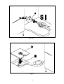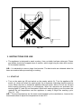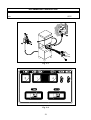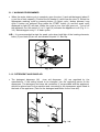
1
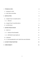
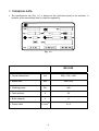
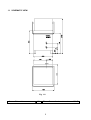
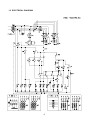
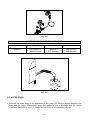
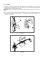
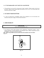
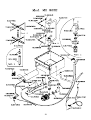
REV.00 15/07/05 COD.6000276.00
INSTRUCTIONS BOOKLET FOR
INSTALLATION-MAINTENANCE
OPERATION
FOR DISH-WASHERS
MS 900E
73/23 - 93/68 - 89/336
Always switch off the appliance at the end of the
work cycle, turn off the water and disconnect the
power supply.
INTRODUCTION
1) Read the instructions in this booklet carefully as they provide important information, use
and maintenance. Keep the booklet to hand in a safe place so that it can be consulted by
other operators.
2) After removing the packing material, check that all the equipment is present and intact.
If there is any doubt, do not use it and contact qualified personnel. The packing elements
(plastic bags, foam polystyrene, nails, etc.) should be kept away from children, because
they are dangerous.
3) Before switching the equipment on, make sure that the model plate data conforms to
that of the electrical and water distribution network.
4) Installation should be carried out by qualified personnel according to the manufacturer’s
instructions.
5) This equipment must be destined to the use which it has been conceived for. Any other
application should be considered improper and consequently dangerous.
6) The equipment should be used by personnel trained for its use only.
7) Do not leave the machine in an environment at temperatures lower than 0°C.
8) The protection of the machine is IPX4, therefore it should not be washed with high
pressure and directed water jets.
9) Qualified personnel only can access the control panel, after having disconnected the
machine from the primary current supply.
2
1. TECHNICAL DATA
4
1.1 SCHEMATIC VIEW
5
1.2 ELECTRICAL DIAGRAM
6
2. INSTALLATION
8
2.1 CONNECTION TO POWER SUPPLY
8
2.1.1 GROUND
8
2.2 CONNECTION TO WATER SUPPLY
9
2.3 WATER DRAIN
10
3. INSTRUCTIONS FOR USE
12
3.1 START UP
12
3.1.1 WASHING PROGRAMMES
14
3.1.2 DETERGENT AND RINSE AID
14
3.2 CLEANING
15
3.3 IF THE DISHWASHER IS NOT USED FOR LONG PERIODS
16
4. IN CASE OF MALFUNCTIONS
16
5. SERVICEABILITY
16
3
1. TECHNICAL DATA
• The specifications tag (Fig. 1-1) is placed on the right-hand panel of the machine. It
contains all the neccessary data to install the appliance.
Fig. 1-1
MS 900E
• Overall dimensions
mm
650 x 710 x 1460
• Basket size
mm
500 x 500
• Washing power
P/h
900
• Tank capacity
lt
34
• Boiler capacity
lt
11
n x mm2
3x4
• Power cable
4
1.1 SCHEMATIC VIEW
Fig. 1-2
A
•
Water drain
∅ 30
• Connection to water mains
B
5
3/4’ G
1.2 ELECTRICAL DIAGRAM
6
Rif.
Description
C1
Suppression filter
CB
Boiler contactor
CL
Power supply contactor
CR-CR1
Relays contactor
CR2 (optional)
Relays contactor
CV
Tank contactor
DB (optional)
Electric additive distributor
DD (optional)
Electric detergent distributor
EB
Boiler solenoid valve
IG
Main switch
M
Terminal board
MP
Door microswitch
PL
Washing pump
PS (optional)
Drainage pump
PV
Tank pressureswitch
R-R1
Relays
R2 (optional)
Relays
RB
Boiler heating element
RV
Tank heating element
SB
Boiler pilot lamp
SC
Start pilot lamp
SCV
Cycle selector
SL
Power pilot lamp
ST
Start
SV
Tank pilot lamp
T
Timer
T1
Timer ciclo1
T2
Timer ciclo2
TB
Boiler thermostat
TPL
Washing pump contactor
TSB
Boiler safety Thermostat
TV
Tank thermostat
7
2. INSTALLATION
• Installation, initial start-up and maintenance of the appliance must be carried out by
qualified personnel only. All hydraulic and electrical connections must be carried out in
compliance with current safety norms. The manufacturer accepts no responsibility for
malfunctions arising from incorrect connection of the appliance. When installing, ensure
that the appliance is perfectly level. Turn the adjustable feet clockwise or anticlockwise to
level the appliance.
The following norms must be observed when installing the appliance:
1. current accident -prevention regulations
2. CE standards
3. water board regulations
2.1 CONNECTION TO POWER SUPPLY
• The electrical panel is located on the front of the appliance. The connection to power
supply is on the back side of the appliance. The power cable (G) must have a rating of at
least H05VVF, and each wire must have a section of 2.5 mm².
N.B. : In accordance with international standards, a cut-out switch (A), provided with
amperage-adequate fuses (see technical specification), must be installed between the
mains electricity supply and appliance. The contacts must have an aperture of at least 3
mm.The main switch (A) should be positioned in the immediate vicinity of the appliance
and should be easily accessible.
Fig. 2-1
2.1.1 GROUND
• The appliance must be grounded. The ground terminal screw is located on the rear panel
of the appliance, and marked by the symbol
.
N.B. : The manufacturer accepts no responsibility or warranty obligations in case of
damage arising from non-compliance with this requirement or from incorrect installation.
8
2.2 CONNECTION TO WATER SUPPLY
•
The appliance is designed for connection to the cold or hot water supply (max. 50 55°C)
at a mains pressure with the valve open as shown in Table 2-1 and a minimum output of
10 litres/min. If pressure exceeds the maximum, fit a pressure reducer. If pressure is
lower than the minimum, fit a pressure booster pump of max. 0.5 HP, with an output of
20 litres/min. and a head of 15÷20 metres. Pressure must be measured at the solenoid
valve inlet (see fig. 2-4). The water pipes must have an internal diameter of at least
16/18 mm (see fig. 2-5). Connect the appliance water supply pipe to a cut-out tap (B),
preferably placed close to the appliance, fitting the special filter provided (B1)
(see fig. 2-2). We recommend fitting a water softener (C) (not provided) upstream from
the machine solenoid valve (see fig.2-3).
Tab. 2-1
Temperature
Pressure
max 50-55 °C
1.5 - 3 bar
Fig. 2-2
Fig. 2-3
INLET WATER PRESSURE
1.5 - 2 bar
2 - 2.5 bar
2.5 - 3 bar
minimum
good
very good
9
Fig. 2-4
WATER/CYCLE DRAIN FOR MAINS RINSE
2.5 litri
2.5 - 3 litri
2.5 - 3 litri
3 - 4 litri
minimum
very good for
glass-washers
good for
dish-washers
very good for
dish-washers
Fig. 2-5
2.3 WATER DRAIN
• Connect the drain hose of the appliance to the outlet (D), fitting a siphon between the
hose and the outlet. Alternatively, place the appliance over a drainage well (E), which
should be fitted with a cover (F) to prevent the build-up of unpleasant odours.
10
Fig. 2-6
Fig. 2-7
11
Fig. 2-8
3. INSTRUCTIONS FOR USE
• The appliance is designed to wash crockery. Use a suitable low-foam detergent. Plates
and dishes should be scraped clean of residue, which might clog the drain and nozzles.
Fill the basket carefully.
N.B. : It is advisable to remove large food remains. The best results are obtained when the
items are washed after pre-washing or soaking.
3.1 START UP
• Turn on the water tap (B) and switch on the master switch (A). Turn the appliance ON
switch (1), which will cause the warning light (A) to illuminate, indicating that the machine
is live. When the door is closed the appliance fills with water. When it is full, the tub and
boiler heating elements come on automatically. When the elements are activated, the
warning lights (C) and (B) are illuminated. When both warning lights go out the water has
reached the set temperature and the appliance is ready to begin the washing cycle.
(Fig. 3-1 - 3-2)
N.B. : The set temperatures are the ones recommended by the manufacturer, however the
thermostats allow to adjust the temperature at max 90°C
12
RECOMMENDED TEMPERATURE
boiler
90°C
tub
60°C
Fig. 3-1
Fig. 3-2
13
3.1.1 WASHING PROGRAMMES
• When the water intake cycle is complete, open the door (I) and add detergent (about 2
g. per litre of tank capacity). Position the full basket (L) and close the door (I). Select the
appropriate washing cycle by pressing button (3) (short cycle I button pressed, long
cycle II button not pressed. Now press the START button (4) and the wash cycle
displayed by light (D) will start. When the cycle is over, this light goes out. To turn off
the appliance, turn the switch (1) to 0. Light (A) indicates the appliance is off (Fig. 3-1 ÷
3-3). Add detergent every 5 - 6 wash cycles.
N.B. : It is recommended ta start the wash cycle when both litgh of the heating elements,
boiler (C) and tank (B) are off, as indicated at point 3.1 Start up.
Fig. 3-3
3.1.2 DETERGENT AND RINSE AID
• The detergent dispenser (M)
rinse aid dispenser
(N) are regulated by the
manufacturer. If the setting needs to be changed, turn the regulating screw on the
dispensers. The detergent and rinse aid containers (if not provided with the appliance)
should be placed next to the machine and connected to the transparent pipes fitted to
the back of the appliance (Tank for the detergent and Boiler for the rinse aid).
Fig. 3-4
14
3.2 CLEANING
• Cleaning is extremely important for proper operation of the appliance. We recommend
cleaning at the end of each work cycle. Turn off the 0-I switch, wash all the removable parts
in running water and replace them with care.
WARNING : Before removing the filters (S) clean residual foreign matter from the bottom of
the tub.
N.B. : Turn off the master switch (A) before cleaning the outer coating, without using direct or
high pressure water jets. Wash all parts of the appliance with neutral detergents (not
corrosive or aggressive).
Fig. 3-5
Fig. 3-6
15
3.3 IF THE DISHWASHER IS NOT USED FOR LONG PERIODS
• If the machine is not used for a long period, clean it carefully. Wash and dry the tub and
the filters. Leave the door open while the machine is not in use. Turn off the water and
disconnect the power supply.
4. IN CASE OF MALFUNCTIONS
• In case of malfunctions, immediately switch off the appliance, turn off the water and
disconnect the power supply. Call a service technician.
5. SERVICEABILITY
IMPORTANT
QUALIFIED PERSONNEL ONLY
• The electrical control panel features all the appliance’s components except : pump,
heating elements, rinse-aid dispenser and solenoid valves. These components can be
accessed by removing the lower front panel.
N.B. : Before any technical service, disconnect the machine from the mains.
(Fig. 5-1)
Fig. 5-1
16
17
18
19
Unit 7, Church Park, Lowfield Heath, Crawley, West Sussex RH11 0PW
Sales: 01293 571199 ▪ Fax: 01293 571133
Email: [email protected] ▪ www.mpswholesale.co.uk
20