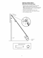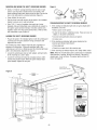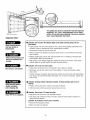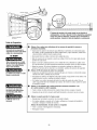
1
Owner's Manual/ManualDel Propietario
CRFIFTSMRN°
GARAGEDOOROPENER
ABRIDORDE PUERTADE COCHERA
ForResidentialUse 0nly/S61opara usoresidencial
Model/Modelo 139.53918D
I"11
z
I"11
'13
;Z=,
Z_
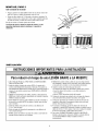
Read andfollow all safetyrules and
operatinginstructionsbeforefirst use of this
product.
Leer y seguirtodas las reglasde seguridady
las instruccionesde operaci6n antesde usar
este productopor primeravez.
Guardareste manual cercade la puerta de la
Fastenthe manual near the garagedoorafter cochera.
installation.
Se debenrealizar revisionesperi6dicas del
Periodic checksof the opener are requiredto abridorde puertas para asegurarsu
operaci6n segura.
ensuresafe operation.
cQus
Sears, Roebuck and Co., Hoffman Estates, IL 60179 U.S.A
www.sears.com/craftsman
TABLE
OF CONTENTS
Introduction
2-7
Safety symbol review and signal word review ...............
2
Preparing your garage door .............................
Tools needed ........................................
3
3
Planning ..........................................
4-5
Adjustment
27-29
Program the travel limits ..............................
Set the force ........................................
27
28
Test the safety reversal system..........................
29
Test The Protector System® ............................
29
Carton inventory ......................................
6
Operation
Hardware inventory....................................
7
Operation safety instructions ...........................
30
Using your garage door opener .........................
30
Using the wall-mounted door control .....................
31
Care of your opener ..................................
32
To open the door manually .............................
32
Battery backup ......................................
33
Having a problem (Troubleshooting) .....................
34
Diagnostic chart .....................................
35
Smart Control Panel¢ messages.........................
36
Assembly
8-11
Assemble the rail and install the trolley ....................
Fastenthe rail to the motor unit ..........................
8
9
Install the idler pulley ..................................
9
Install the belt and attach the belt cap retainer..............
10
Set the tension ......................................
11
Installation
11-26
30-36
Installation safety instructions ..........................
11
Determine the header bracket location ....................
12
Install the header bracket ..............................
13
To add or reprogram a hand-held remote control ...........
37
Attach the rail to the header bracket......................
14
Position the opener...................................
15
To erase all codes from motor unit memory ...............
3-Button remotes ....................................
37
37
Hang the opener .....................................
Install the door control ................................
16
17
To add, reprogram or change a
Keyless Entry PIN ....................................
38
Install the battery ....................................
18
Programming
Repair Parts
37-38
39-40
Rail assembly parts ..................................
39
39
Install the lights .....................................
18
Attach the emergency release rope and handle .............
18
Installation parts .....................................
Electrical requirements ................................
19
Motor unit assembly parts .............................
40
Accessories
41
Warranty
41
Install The Protector System® .......................
Fastenthe door bracket ............................
20-22
23-24
Connect the door arm to the trolley ...................
25-26
Repair Parts & Service
Back Cover
INTRODUCTION
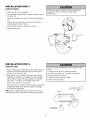
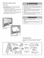
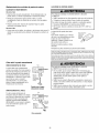
Safety SymbolReviewand Signal WordReview
This garage door opener has been designed and tested to offer safe service provided it is installed, operated, maintained and tested in
strict accordancewith the instructions and warnings contained in this manual.
Mechanical
Electrical
When you see these Safety Symbols and Signal Words on the
following pages, they will alert you to the possibility of serious
injury or death if you do not comply with the warnings that
accompany them. The hazard may come from something
mechanical or from electric shock. Readthe warnings carefully.
When you see this Signal Word on the following pages, it will
alert you to the possibility of damageto your garage door and/or
the garage door opener if you do not comply with the cautionary
statements that accompany it. Readthem carefully.
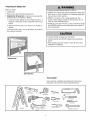
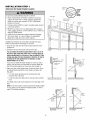
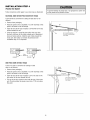
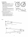
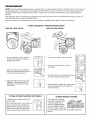
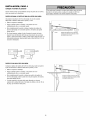
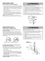
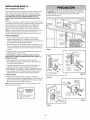
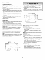
Preparingyour garage door
Before you begin:
• Disable locks.
To prevent possible SERIOUSINJURYor DEATH:
• ALWAYScall a trained door systems technician if garage door
binds, sticks, or is out of balance. An unbalanced garage door
may not reverse when required.
• Removeany ropes connected to garage door.
• Complete the following test to make sure your garage door
is balancedand is not sticking or binding:
• NEVERtry to loosen, move or adjust garage door, door
springs, cables, pulleys, brackets or their hardware, ALL of
which are under EXTREMEtension.
1. Lift the door about halfway as shown. Releasethe door. If
balanced, it should stay in place, supported entirely by its
springs.
• DisableALL locks and remove ALL ropes connected to garage
door BEFOREinstalling and operating garage door opener to
avoid entanglement.
2. Raise and lower the door to see if there is any binding or
sticking.
If your door binds, sticks, or is out of balance, call a trained
door systems technician.
To prevent damage to garage door and opener:
• ALWAYSdisable locks BEFOREinstalling and operating the
opener.
• ONLY operate garage door opener at 120V, 60 Hz to avoid
malfunction and damage.
Sectional Door
One-Piece Door
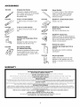
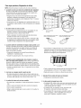
Tools needed
During assembly, installation and adjustment of the opener,
instructions will call for hand tools as illustrated below.
Level (optional)
Pencil
Hack Saw
Tape Measure
Claw Hammer
Drill
3/16", 5/16"
_1
Stepladder
8_
Wire Cutters
Screwdriver
and 5/32"
_/°2c'
_e5t/s8
"a,
7d/lW6
"r,e
;/clh"
Pliers
Adjustable End Wrench
and 1/4"
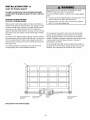
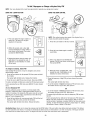
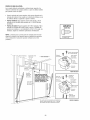
P_nnmg
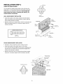
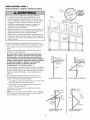
Identify the type and height of your garage door. Survey your
garage area to see if any of the conditions below apply to your
installation. Additional materials may be required. You may find it
helpful to refer back to this page and the accompanying
illustrations as you proceed with the installation of your opener.
Doyou have an access door in addition to the garage door? If
not, Model 139.53702 Emergency Key Releaseis required. See
Accessories page.
Look at the garage door where it meets the floor. Any gap
between the floor and the bottom of the door must not exceed
1/4" (6 mm). Otherwise, the safety reversal system may not
work properly. See Adjustment Step 3. Floor or door should be
repaired.
Depending on your requirements, there are several installation
steps which may call for materials or hardware not included in
the carton.
• Installation Step 1 - Look at the wall or ceiling above the
garage door. The header bracket must be securely fastened to
structural supports.
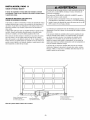
SECTIONALDOORINSTALLATION
• Doyou have a steel, aluminum, fiberglass or glass panel door?
If so, horizontal and vertical reinforcement is required
(Installation Step 12).
• Installation Step 5 - Do you have a finished ceiling in your
garage? If so, a support bracket and additional fastening
hardware may be required.
• The opener should be installed above the center of the door. If
there is a torsion spring or center bearing plate in the way of
the header bracket, it may be installed within 4 feet (1.22 m)
to the left or right of the door center. See Installation Steps 1
and 12.
• Installation Step 11 - Dependingupon garage construction,
extension brackets or wood blocks may be needed to install
sensors.
• Installation Step 11 - Alternate floor mounting of the safety
reversing sensor will require hardware not provided.
• If your door is more than 7 feet (2.13 m) high, see rail
extension kits listed on Accessories page.
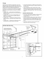
SECTIONALDOOR INSTALLATION
FINISHED CEILING
Support bracket &
fastening hardware
is required.
See page 16.
Horizontal and vertical reinforcement
is needed for lightweight garage doors
(fiberglass, steel, aluminum, door with
glass panels, etc.). See page 23 for details.
Rail
Header Wall
tor unit
Extension Spring
OR
Torsion Spring
Wallmounted
Door
Control
Access Door
0
CLOSEDPOSITION
Header
Bracket
Gap between floor
and bottom of door
Reversing Sensor
Trolley
Stop Bolt
Safety
Reversing
Sensor
Trolley
Belt
mustnot exceed1/4"(6 mm).
Emergency Release
Rope & Handle
Curved
Door
Arm
Header
Wall
Garage
Door
Bracket
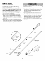
Planning(Continued)
ONE-PIECEDOOR INSTALLATIONS
• Generally, a one-piece door does not require reinforcement. If
your door is lightweight, refer to the information relating to
sectional doors in Installation Step 12.
• Dependingon your door's construction, you may need
additional mounting hardware for the door bracket (Step 12).
ONE-PIECEDOORWITHOUTTRACK
Without a properly working safety reversal system, persons
(particularly small children) could be SERIOUSLYINJUREDor
KILLEDby a closing garage door.
• The gap between the bottom of the garage door and the floor
MUST NOT exceed 1/4" (6 mm). Otherwise, the safety
reversal system may not work properly.
• The floor or the garage door MUST be repaired to eliminate
the gap.
FINISHEDCEILING
Support bracket
& fastening
hardware is required.
See page 16.
Rail
Header Wall
Motor Unit
Wall-Mounted
Door Control
J
Access
Door
CLOSEDPOSITION
Trolley Stop Bolt
,_
o
Belt
r uracKet
Trolley
I
_
J/
I
Sensor
SafetyReversing
Sensor
Gap between floor
and bottom of door must
not exceed 1/#' (6 mm).
it liirght
_
Garage
_,_
Door
ii_e
d _
CLOSED POSITION
Belt
Trolley
Access
Door
Header
Wall
Rail
ol
Door
Bracket
Garage
Door
Safety
Reversing Sensor
Gap between floor
and bottom of door
must not exceed
1/4" (6 mm).
Safety
Reversing Sensor
Straight
Door
Arm
Rope & Handle
°
ONE-PIECEDOORWITH TRACK
Trolley Stop Bolt
Emergency
I-- Release
Safety Reversing
Release
Rope &
Handle
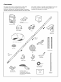
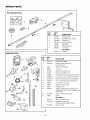
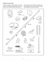
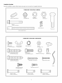
CartonInventory
Your garage door opener is packaged in one carton which
contains the motor unit and all parts illustrated below.
Accessories will depend on the model purchased. If anything is
missing, carefully check the packing material. Parts may be stuck
in the foam. Hardwarefor assembly and installation is shown on
the next page. Savethe carton and packing material until
installation and adjustment is complete.
SECURITY+ ®
3 Function Remote Control (2)
Battery
Smart Control Panel®
Belt Cap Retainer
Trolley
SECURITY+®
Keyless Entry
Rail
Center/Back
Sections
Io
i
Motor Unit with 2 Light Lenses
1°
_PI,,
Io
Io
%
Idler Pulley
Hanging Brackets
Belt
Rail
Front (header)
Section
Curved Door
Arm Section
Header Bracket
Door Bracket
2-Conductor Bell Wire
White & White/Red
Safety Reversing
Sensor Bracket (2)
The Protector System ®
(2) Safety Reversing Sensors
(1 Sending Eye and 1 Receiving Eye)
with 2-Conductor White & White/Black
Bell Wire attached
Safety Labels
and
Literature
Straight Door
Arm Section
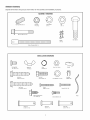
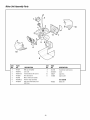
HardwareInventory
Separateall hardware and group as shown below for the assembly and installation procedures.
ASSEMBLYHARDWARE
Spring/Trolley Nut (1)
Lock Nut
1/4"-20 (2)
Lock Washer
3/8" (1)
Nut
3/8" (1)
Idler Bolt (1)
Master
Link (2)
I©
Trolley Threaded Shaft (1)
INSTALLATIONHARDWARE
©
Carriage Bolt
1/4"-20xl/2" (2)
Wing Nut
1/4"-20 (2)
Ring
Fastener (3)
Handle
Nut 5/16"-18 (4)
1111111111_
Lag Screw
5/16"-9xl -5/8" (2)
111111111111_>
Hex Bolt
5/16"-18x7/8" (4)
Lock Washer 5/16" (5)
_ IIlllllllllllMlllllIlllll_
Lag Screw
5/16"-18xl-7/8" (2)
_ IIIIIIIIIIIIIIIIIIlll
Screw
6ABx1-1/4" (2)
Self-Threading Screw
1/4"-14x5/8" (2)
Insulated
Staples (30)
Screw 6-32x1" (2)
Rope
Drywall Anchors (2)
on
Clevis Pin
5/16"x1-1/2" (1)
Clevis Pin
5/16"x1" (1)
Clevis Pin
5/16"x1-1/4"(1)
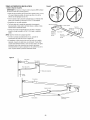
ASSEMBLY
STEP
1
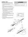
Assemble the Rail and Install the Trolley
To prevent INJURY from pinching, keep hands and fingers
away from the joints while assembling the rail.
To avoid installation difficulties, do not run the garage door
opener until instructedto do so.
The front rail has a cut out "window" at the door end
(see illustration). The hole above this windowis larger on the
top of the raft than on the bottom. A smaller hole 3-1/2" (8.9 cm)
away is close to the rail edge. Rotate the back rail so it has a
similar hole close to the opposite edge,about 4-3/4" (12 cm)
from the far end.
1. Removethe straight door arm and hanging bracket
packaged inside the front rail and set aside for Installation
Steps 5 and 12.
NOTE: To prevent INJURY while unpacking the rail carefully
remove the straight door arm stored within the rail section.
3. Placethe motor unit on packing material to protect the cover,
and rest the back end of the rail on top. For convenience, put a
support under the front end of the rail.
4. As a temporary stop, insert a screwdriver into the hole
10" (25 cm) from the front end of the rail, as shown.
5. Checkto be sure there are 4 plastic wear pads inside the inner
trolley. If they became loose during shipping, check all packing
material. Snap them back into position as shown.
6. Slide the trolley assembly along the rail from the back end to
the screwdriver.
2. Align the rail sections on a flat surface as shown and slide the
tapered ends into the larger ones. Tabs along the side will lock
into place.
Trolley
)ered
End
)ered
End
E3ack
Rails
(TO MOTOR UNIT)
)ered
End
_ered
End
rewdrive_
"11
Window
O
Cut-Ou_
///
Idler
Pulley
Hole
_,//_._'/
_
i
///
InnerTrolley
Tabs
///
Front Rail
(TO DOOR)
v
_ WearPads
__
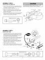
ASSEMBLY
STEP 2
Fastenthe Rail to the Motor Unit
To avoid SERIOUSdamageto garage door opener, use ONLY
those bolts/fasteners mounted in the top of the opener.
• Insert a 1/4"-20xl-3/4 bolt into the cover protection bolt hole
on the back end of the rail as shown. Tighten securely with a
1/4"-20 lock nut. DO NOTovertighten.
• Removethe two bolts from the top of the motor unit.
• Placethe "U" bracket, flat side down, on the motor unit and
align the bracket holes with the bolt holes. Fastenwith the
previously removed bolts.
Bolts _
Belt Pulley
Unit
"U" Bracket
• Align the rail assembly with the top of the motor unit. Slide the
rail end onto the "U" bracket, all the way to the stops that
protrude on the top and sides of the bracket.
Bolt
I
Cover
Protection
Bolt Hole X
HARDWARESHOWN ACTUALSIZE
SLIDE RAIL TO STOPS
ON TOP AND SIDES
OF BRACKET
@ Lock Nu
Bolt 1/4"-20xl-3/4"
ASSEMBLY
STEP
Lock Nut I
1/4"-20
3
Install the Idler Pulley
• Laythe belt beside the rail, as shown. Graspthe end with the
hooked trolley connector and pass approximately 12" (30 cm)
of belt through the window. Keepthe ribbed side toward the
rail, and allow it to hang until Assembly Step 5.
• Removethe tape from the idler pulley. The inside center should
be pre-greased. If dry, regreaseto ensure proper operation.
• Placethe idler pulley into the window as shown.
• Insert the idler bolt from the top through the rail and pulley.
Tighten with a 3/8" lock washer and nut underneaththe rail
until the lock washer is compressed.
Bolt
• Rotatethe pulley to be sure it spins freely.
• Insert a 1/4"-20xl-3/4 bolt into the trolley stop hole in the front
of the rail as shown. Tighten securely with a 1/4"-20 lock nut.
_ _.
Grease
Pulley
Inside
__
- _
Idler Pulley
Lock Washer 3/8"-_
Nut 3/8"
I
Trolley
Connector
Idler _
Pulley ,
HARDWARESHOWN ACTUALSIZE
Idler Bo_
_]
Bolt 1/4"-20xl-3/4"
Lock Nut 1/4"-20
Nut 3/8"
Lock Washer 3/8"
Lock
Nut
ASSEMBLY
STEP
4
Insta// the Be/t and Attach the Be/t Cap Retainer
To avoid possible SERIOUSINJURYto fingers from moving
garage door opener:
• ALWAYS keep hand clear of belt pulley while operating
opener.
• Securely attach belt pulley cover BEFOREoperating.
1. Pull the belt around the idler pulley and toward the trolley.
Theribbed side must contact the pufley.
2. Hook the trolley connector into the retaining slot on the trolley
as shown.
3. With the trolley against the screwdriver, dispense the
remainder of the belt along the rail length toward the motor
unit and around the sprocket. The sprocket teeth must engage
the belt.
4. Checkto make sure the belt is not twisted and the FLAT side
of the trolley threaded shaft is facing the rail. Connect the
trolley threaded shaft with the master link, as illustrated:
• Push pins of master link bar through holes in end of belt
and trolley threaded shaft.
• Push master link cap over pins and past pin notches.
• Slide clip-on spring over cap and onto pin notches until
both pins are securely locked in place.
5. Insert the trolley threaded shaft through the hole in the trolley.
Be sure the belt is not twisted and the FLAT side of the trolley
threaded shaft faces the rail.
HARDWARESHOWN ACTUALSIZE
6. Hold the belt at the trolley shaft as you thread the spring nut
by hand onto the shaft until finger tight against the trolley.
DONOT use any tools.
7. Removethe screwdriver.
Hex Screw 8x3/8"
Spring/Trolley Nut
8. Position the belt cap retainer over the motor unit sprocket as
shown and fasten to the mounting plate with 8x3/8" hex
screws provided.
Master Link
Clip-On Spring
Master Link Cap
Pin
Trolley
Threaded
Shaft
._
Notch|
Master
Link Bar
Hole
HexScrews
#8x3/8"
Retaining
Trolley
Slot
Connector
Idler Pulley
Belt Cap
Retainer
Motor Unit
Belt Pulley
Plate
10
ASSEMBLY
STEP
Set the Tension
5
• Insert a screwdriver tip into one of the nut ring slots and brace
it firmly against the trolley.
f
f
• Place a 7/16" open end wrench on the square end. Rotate the
nut about 1/4 turn until the spring releasesand snaps the nut
ring against the trolley.
This sets the spring to optimum belt tension.
Youhave now finishedassemblingyour garage door opener.
P/ease read the following warningsbeforeproceedingto the
insta//ation section.
-- Nut Ring Slot
Square End
Trolley
Square
End
Nut Rinc
(2.5 cm)
Nut Rin,
ER RELEASE
1-1/4"
(3.18 cm)
INSTALLATION
IMPORTANTINSTALLATIONINSTRUCTIONS
To reducethe risk of SEVEREINJURYor DEATH:
1. READAND FOLLOWALL INSTALLATIONWARNINGS
AND INSTRUCTIONS.
8. NEVERwear watches, rings or loose clothing while
installing or servicing opener. They could be caught in
garage door or opener mechanisms.
2. Install garage door opener ONLYon properly balanced
and lubricated garage door. An improperly balanced door
may not reversewhen required and could result in
SEVEREINJURYor DEATH.
9. Install wall-mounted garage door control:
• within sight of the garage door.
• out of reachof children at minimum height of
5 feet (1.5 m).
3. ALL repairs to cables, spring assemblies and other
hardware MUST be made by a trained door systems
technician BEFOREinstalling opener.
4. Disable ALL locks and remove ALL ropes connected to
garage door BEFOREinstalling opener to avoid
entanglement.
5. Install garage door opener 7 feet (2.1 m) or more above
floor.
• away from ALL moving parts of the door.
10. Place entrapment warning label on wall next to garage
door control.
11. Placemanual release/safety reverse test label in plain view
on inside of garage door.
12. Upon completion of installation, test safety reversal
system. Door MUST reverse on contact with a
1-1/2" (3.8 cm) high object (or a 2x4 laid flat) on the
floor.
6. Mount emergency releasehandle 6 feet (1.8 m) above
floor.
7. NEVERconnect garage door opener to power source
until instructed to do so.
13. To avoid SERIOUSPERSONALINJURYor DEATHfrom
electrocution, disconnect ALL electric and battery power
BEFOREperforming ANY service or maintenance.
11
INSTALLATION
STEP 1
Determine the HeaderBracketLocation
Unfinished
Ceiling
To prevent possible SERIOUSINJURYor DEATH:
• Headerbracket MUST be RIGIDLY fastened to structural
support on header wall or ceiling, otherwise garage door
might not reversewhen required. DO NOT install header
bracket over drywall.
• Concrete anchors MUST be used if mounting header bracket
or 2x4 into masonry.
• NEVERtry to loosen, move or adjust garage door, springs,
cables, pulleys, brackets, or their hardware, ALL of which are
under EXTREMEtension.
OPTIONAL
CEILING
MOUNT
!FOR
HEADER
BRACKET
HeaderWall
Vertical Centerline
of Garage Door
2x4
Structural
Supports
• ALWAYScall a trained door systems technician if garage
door binds, sticks, or is out of balance. An unbalanced
garage door might not reverse when required.
Installation procedures vary according to garage door types.
Follow the instructions which apply to your door.
1. Close the door and mark the inside vertical centerline of the
garage door.
2. Extend the line onto the header wall above the door.
You can fasten the header bracketwithin 4 feet (1.22 m) of
the left or right of the doorcenter only if a torsion springor
center bearingplate is in the way; or you can attach it to the
ceiling (see page 13) when clearance is minimal. (It may be
mountedon the wall upsidedown if necessary,to gain
approximately1/2" (1 cm).)
Header Wall
Track
If you need to install the header bracket on a 2x4 (on wall or
ceiling), use lag screws (not provided) to securely fasten the
2x4 to structural supports as shown here and on page 13.
HeaderWall
Track
Highest Point
of Travel
Y
Door
3. Open your door to the highest point of travel as shown. Draw
an intersecting horizontal line on the header wall above the
high point:
t
e"
T
• 2" (5 cm) above the high point for sectional door and
one-piece door with track.
• 8" (20 cm) above the high point for one-piece door without
track.
Sectional door with curvedtrack
One-piece door with horizontal track
This height will provide travel clearance for the top edge of the
door.
NOTE:If the total number of inches exceedsthe height available
in your garage, use the maximum height possible, or refer to
page 13 for ceiling installation.
Header Wall
:-
all
"
_Highest
Door
8" (20 cm)
-;"
I_#..-;"
41-:-_'_/I
._-"
", Highest
,', Point
',',
of Travel
',
Hardware
One-piece
doorwithouttrack:
jambhardware
12
One-piece door without track:
pivot hardware
INSTALLATION
STEP
Install the Header Bracket
2
Wall Mount
You can attach the header bracket either to the wall above the
garage door, or to the ceiling. Follow the instructions which will
work best for your particular requirements. Do not install the
header bracket over drywall. If installing into masonry, use
concreteanchors(not provided).
Optional
Mounting Holes
WALL HEADERBRACKETINSTALLATION
• Center the bracket on the vertical centerline with the bottom
edge of the bracket on the horizontal line as shown (with the
arrow pointing toward the ceiling).
-
• Mark the vertical set of bracket holes. Drill 3/16" pilot holes and
fasten the bracket securely to a structural support with the
hardware provided.
Vertical
Centerline
of Garage Door
Header Wall -
2x4
Structural
SuppoR
_
Lag
Screws
5/16"-9xl
-5/8"
Door Spring
J
1
HARDWARESHOWN ACTUALSIZE
Horizontal
Line
-
i
Highest Point of
Garage Door Travel
Lag Screw
5/16"-9xl -5/8"
Garage Door -
Vertical
Centerline
of Garage Door
CEILINGHEADERBRACKETINSTALLATION
• Extend the vertical centerline onto the ceiling as shown.
• Center the bracket on the vertical mark, no more than
6" (15 cm) from the wall. Make sure the arrow is pointing away
from the wall. The bracket can be mounted flush against the
ceiling when clearance is minimal.
• Mark the side holes. Drill 3/16" pilot holes and fasten bracket
securely to a structural support with the hardware provided.
- FinishedCeilingVerticalCenterline
of GarageDoor
i
Bracket
6" (15 cm) M
Ceiling Mounting Holes
Door
Spring
"
Lag Screws
5/16"-9xl -5/8"
Header Wall -
13
INSTALLATION
STEP 3
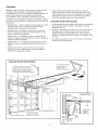
Attachthe Rail to the HeaderBracket
• Position the opener on the garage floor below the header
bracket. Use packing material as a protective base.
NOTE: If the door spring is in the way, you will need help. Have
someone hold the opener securely on a temporary support to
allow the rail to clear the spring.
• Position the rail bracket against the header bracket.
• Align the bracket holes and join with a clevis pin as shown.
• Insert a ring fastener to secure.
Header Wall
Header Bracket
Idler Pulley
Ring
Fastener
Clevis Pin
Mounting
Hole
__
Garage
Door
--
HARDWARESHOWN ACTUALSIZE
ol
ClevisPin5/16"x1-1/2"
14
©
Ring Fastener
Opener Carton or
Temporary
Support
INSTALLATION
STEP
4
Positionthe Opener
To prevent damage to garage door, rest garage door opener rail
on 2x4 placed on top section of door.
Follow instructions which apply to your door type as illustrated.
SECTIONALDOOROR ONE-PIECEDOORWITH TRACK
A 2x4 laid flat is convenient for setting an ideal door-to-rail
distance.
• Removefoam packaging.
Rail
• Raisethe opener onto a stepladder. You will need help at this
point if the ladder is not tall enough.
• Open the door all the way and place a 2x4 laid flat on the top
section beneath the rail.
• If the top section or panel hits the trolley when you raise
the door, pull down on the trolley releasearm to disconnect
inner and outer sections. Slide the outer trolley toward the
motor unit. The trolley can remain disconnected until
Installation Step 12 is completed.
2x4 is used to determine
the correct mounting height
from ceiling.
Door
Iley
ReleaseAml -ENGAGED
RELEASED
_
J
_j
ONE-PIECEDOORWITHOUTTRACK
A 2x4 on its side is convenient for setting an ideal
door-to-rail distance.
• Removefoam packaging.
• Raisethe opener onto a stepladder. You will need help at this
point if the ladder is not tall enough.
L_
• Open the door all the way and place a 2x4 on its side on the
top section of the door beneath the rail.
• The top of the door should be level with the top of the motor
unit. Do not position the opener more than 4" (10 cm) above
this point.
15
Header
INSTALLATION
STEP
5
Hang the Opener
To avoid possible SERIOUSINJURYfrom a falling garage door
opener, fasten it SECURELYto structural supports of the
garage. Concrete anchors MUST be used if installing ANY
brackets into masonry.
Three representative installations are shown. Yours may be
different. Hanging brackets should be angled (Figure 1) to provide
rigid support. On finished ceilings (Figures 2 and 3), attach a
sturdy metal bracket to structural supports before installing the
opener. This bracket and fastening hardware are not provided.
1. Measure the distance from each side of the motor unit to the
structural support.
Figure1
2. Cut both pieces of the hanging bracket to required lengths.
)orts
3. Drill 3/16" pilot holes in the structural supports.
4. Attach one end of each bracket to a support with
5/16"-18xl -7/8" lag screws.
Measure
Distance
5. Fastenthe opener to the hanging brackets with
5/16"-18x7/8" hex bolts, lock washers and nuts.
',
Lag Screws
5/16"-18xl -7/8"
Bolt 5/16"-18x7/8"
Lock Washer 5/16"
Nut 5/16"-18
6. Checkto make sure the rail is centered over the door (or in line
with the header bracket if the bracket is not centered above
the door).
7. Removethe 2x4. Operatethe door manually. If the door hits
the rail, raise the header bracket.
NOTE: DONOT connect power to opener at this time.
Figure 2
Hidden
Bracket
(Not Provided)
Support
---"
1''
. -. -_"
_
*"
._
._----
- _- L - _L__--
_
- __
_--_
_-_-
.....
FINISHED CEILING
Lag Screws
-722_
....
_\_
__(Not
_-- -_\o_ - - - - -j---- - Bolt 5/
.--'_'_'--
\_'_&
\_\
Provided)
j_/_/"'_
SoIt 5/16"-18x7/8"
LIo/
Lock Washer 5/16"
Ilol
_/_
NutR5/16"-116,,_18X7/8,
HARDWARESHOWN ACTUALSIZE
N°uCt
k5W_qeer5/16'
_J_'"__(___
__
@
Hex Bolt
5/16"-18x7/8"
Nut 5/16"-18
Figure3
Lag Screws
5/16"-18xl -7/8"
Lock Washer 5/16"
FINISHED CEILING
Bolt 5/16"-18x7/8"
Lock Washer 5/16"
Nut 5/16"-18
16
(Not Provided)
Bolt 5/16"-18x7/8"
Lock Washer 5/16"
Nut 5/16"-18
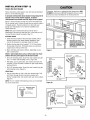
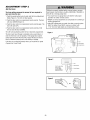
INSTALLATION
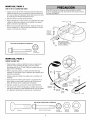
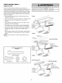
STEP
Install the Door Control
6
To prevent possible SERIOUSINJURYor DEATHfrom
electrocution:
Locate door control within sight of door, at a minimum height of
5 feet (1.5 m) where small children cannot reach, away from
moving parts of door and door hardware. If installing into drywall,
drill 5/32" holes and use the anchors provided. For pre-wired
installations (as in new home construction), it may be mounted to
a single gang box (Figure 2).
• DisconnectALL electric and battery power BEFORE
performing ANY service or maintenance.
• Connect ONLYto 24 VOLT low voltage wires.
To prevent possible SERIOUSINJURYor DEATHfrom a closing
garage door:
1. Strip 7/16" (11 mm) of insulation from one end of bell wire and
connect to the two screw terminals on back of door control by
color: white wire to 2 and white/red wire to the 1.
• Install door control within sight of garage door, out of reach
of children at a minimum height of 5 feet (1.5 m), and away
from ALL moving parts of door.
2. Removecover by gently prying at slot in top of the cover
with a small flat head screwdriver. Fastenwith 6ABx1-1/4"
self-tapping screws (drywall installation) or 6-32x1" machine
screws (into gang box) as follows:
• NEVERpermit children to operate or play with door control
push buttons or remote controls.
• Activate door ONLYwhen it can be seen clearly, is properly
adjusted, and there are no obstructions to door travel.
• ALWAYS keep garage door in sight until completely closed.
NEVERpermit anyone to cross path of closing garage door.
• Install bottom screw, allowing 1/8" (3 mm) to protrude above
wall surface.
• Position bottom of door control on screw head and slide
down to secure. Adjust screw for snug fit.
Outside KeylockAccessoryConnections
• Drill and install top screw with care to avoid cracking plastic
housing. DO NOT overtighten.
To opener quick-connect terminals: white to white;
white/red to red.
• Insert top tabs and snap on cover.
3. (For standard installation only} Run bell wire up wall and
across ceiling to motor unit. Use insulated staples to secure
wire in several places. Do not pierce wire with a staple,
creating a short or open circuit.
HARDWARESHOWN ACTUALSIZE
_
(std installation)
4. Strip 7/16" (11 mm) of insulation from end of bell wire.
Connect bell wire to the quick-connect terminals as follows:
white to white and white/red to red.
(pre-wired)
Insulated
Staples
Drywall Anchors
5. Position the antenna wire as shown.
6. Use tacks or staples to permanently attach entrapment warning
label to wall near door control, and manual release/safety
reversetest label in a prominent location on inside of garage
door.
Insert Top
NOTE: DONOT connect power and operate opener at this time.
The trolley will travel to the furl open position but will not return
to the close position until the sensor beam is connected and
properly aligned.
To
Replace
Push
Bar Cover
. ..
ueu
Wire
_Top
_1+
|1
H
DoorControlConnections
--
+1 ) Mounting
I | Hole
I_ '
__Terminal
II
I_
"
Figure 1
REMOVE & REPLACECOVER
' "
(BACK VIEW)
I Wire
To release or insert wire,
_ush in tab with screwdriver tip
Strip wire 7/16" (11 mm)
_7/16"
TI/
(11 ram)
screws
Bottom
\
:led White Grey
Mounting
Hole
17
Figure2
PRE-WIRED INSTALLATION
INSTALLATION
STEP
7
Install the Battery
•
Make sure motor unit is unplugged.
•
Using a Phillips head screwdriver, remove the battery cover on
the motor unit.
•
Partially insert battery into motor unit with terminals facing
out.
•
Oonnect the red (+) and black (-) wires from motor unit to
corresponding terminals on battery.
•
Verify the battery wires are seated in the channel.
•
Replace battery cover.
ALWAYSwear protective gloves and eye protection when
changing the battery or working around the battery
compartment.
_i_e
INSTALLATION
STEP
ry Cover
8
Install the Lights
To prevent possible OVERHEATINGof the endpanel or light
socket:
• Press the releasetabs on both sides of lens. Gently rotate lens
back and downward until the lens hinge is in the fully open
position. Do not remove the lens.
• DONOT use short neck or specialty light bulbs.
• DONOT use halogen bulbs. Use ONLY incandescent.
To prevent damage to the opener:
• Install up to a 100 watt maximum light bulb in each socket.
Light bulb size should be A19, standard neck only. The lights
will turn ON and remain lit for approximately 4-1/2 minutes
when power is connected. Then the lights will turn OFF.
• DONOT use bulbs larger than IOOW.
• ONLY use A19 size bulbs.
• Reversethe procedure to close the lens.
• If the bulbs burn out prematurely due to vibration, replacewith
a garage door opener bulb. Use A19, standard neck garage
door opener for replacement.
1O0 Watt
Standard Light Bulb
NOTE: Use only standard light bulbs. The use of short neck or
speciality light bulbs may overheat the endpanel or light socket.
Release Tab
Hinge
100 Watt (Max)_'_
Standard Light Bulb
18
/
_...._
INSTALLATION
STEP
9
Attachthe EmergencyRelease Ropeand Handle
• Thread one end of the rope through the hole in the top of the
red handle so "NOTICE"reads right side up as shown. Secure
with an overhand knot at least 1" (2.5 cm) from the end of the
rope to prevent slipping.
• Thread the other end of the rope through the hole in the release
arm of the outer trolley.
• Adjust rope length so the handle is 6 feet (1.83 m) above the
floor. Ensurethat the rope and handle clear the tops of all
vehicles to avoid entanglement. Secure with an overhand knot.
To prevent possible SERIOUSINJURYor DEATHfrom a falling
garage door:
• If possible, use emergency releasehandle to disengage
trolley ONLYwhen garage door is CLOSED.Weak or broken
springs or unbalanceddoor could result in an open door
falling rapidly and/or unexpectedly.
• NEVERuse emergency releasehandle unless garage doorway
is clear of persons and obstructions.
• NEVERuse handle to pull door open or closed. If rope knot
becomes untied, you could fall.
NOTE:If it is necessary to cut the rope, heat seal the cut end with
a match or lighter to prevent unraveling.
Trolley
I
Release
Handle
Emergency
_
INSTALLATION
STEP
,_verhandnot
10
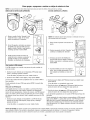
Electrical Requirements
To prevent possible SERIOUSINJURYor DEATHfrom
electrocution or fire:
To avoid installation difficulties, do not run the opener at this
time.
• DisconnectALL electric and battery power BEFORE
performing ANY service or maintenance.
• Garage door installation and wiring MUST be in compliance
with ALL local electrical and building codes.
• NEVERuse an extension cord, 2-wire adapter, or change
plug in ANY way to make it fit outlet. Be sure the opener
is grounded.
To reduce the risk of electric shock, your garage door opener has
a grounding type plug with a third grounding pin. This plug will
only fit into a grounding type outlet. If the plug doesn't fit into the
outlet you have, contact a qualified electrician to install the proper
outlet.
PERMANENTWIRING
CONNECTION
If permanent wiring is required by your local code, refer to the
following procedure.
Ground Tab
Green
Ground Screw
To make a permanent connection through the 7/8" hole in the top
of the motor unit:
Ground Wire
Wire
• Removethe motor unit cover screws and set the cover aside.
• Removethe attached 3-prong cord.
• Connect the black (line) wire to the screw on the brass
terminal; the white (neutral) wire to the screw on the silver
terminal; and the ground wire to the green ground screw.
The opener must be grounded.
• Reinstallthe cover.
White Wire
To avoid installation difficulties, do not run the opener at this
time.
19
Black Wire
INSTALLATION
STEP
11
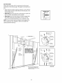
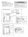
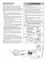
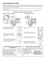
Install The ProtectorSystem®
Be sure power is not connected to the garage door opener
BEFOREinstalling the safety reversing sensor.
The safety reversingsensormust be connectedand aligned
correctlybefore the garage door opener will move in the down
direction.
To prevent SERIOUSINJURY or DEATHfrom a closing garage
door:
• Correctly connect and align the safety reversing sensor. This
required safety device MUST NOT be disabled.
IMPORTANTINFORMATIONABOUT
THE SAFETYREVERSINGSENSOR
When properly connected and aligned, the sensor will detect an
obstacle in the path of its electronic beam. The sending eye (with
an amber indicator light) transmits an invisible light beam to the
receiving eye (with a green indicator light). If an obstruction
breaks the light beam while the door is closing, the door will stop
and reverseto full open position, and the opener lights will flash
10 times.
The units must be installed inside the garage so that the sending
and receiving eyes face each other across the door, no more than
6" (15 cm) above the floor. Either can be installed on the left or
right of the door as long as the sun never shines directly into the
receiving eye lens.
The mounting brackets are designed to clip onto the track of
sectional garage doors without additional hardware.
I
I
I
I
Safety Reversing Sensor
6" (15 cm) max.
above floor
• Install the safety reversing sensor so beam is NO HIGHER
than 6" (15 cm) above garage floor.
If it is necessaryto mount the units on the wall, the brackets
must be securely fastened to a solid surface such as the wall
framing. Extension brackets (see accessories) are available if
needed. If installing in masonry construction, add a piece of wood
at each location to avoid drilling extra holes in masonry if
repositioning is necessary.
The invisible light beam path must be unobstructed. No part of
the garage door (or door tracks, springs, hinges, rollers or other
hardware) may interrupt the beam while the door is closing.
I
I
I
I
Safety Reversing Sensor
6" (15 cm) max,
above floor
Invisible Light Beam
Protection Area
Facing the doorfrom inside the garage
2O
INSTALLINGTHE BRACKETS
Be sure power to the opener is disconnected.Installand align
the brackets so the sensors will face each other across the garage
door, with the beam no higher than 6" (15 cm) above the floor.
They may be installed in one of three ways, as follows.
DOORTRACK MOUNT (RIGHT SIDE)
1
,oure
oo
r Ik
]Track
1I:
Garage doortrack installation (preferred):
L,p
• Slip the curved arms over the rounded edge of each door track,
with the curved arms facing the door. Snap into place against
the side of the track. It should lie flush, with the lip hugging the
back edge of the track, as shown in Figure 1.
If your door track will not support the bracket securely, wall
installation is recommended.
Safety
__ . Reversing
_i
_--_
:::
Indicator
_..,.%('_" Sensor
"_
Waft installation (Figures2 and 3):
• Placethe bracket against the wall with curved arms facing the
door. Be sure there is enough clearancefor the sensor beam to
be unobstructed.
Bracket
WALL MOUNT (RIGHT SIDE)
Figure2
Fasten Wood Block to Wall with
• If additional depth is needed,an extension bracket
(see Accessories) or wood blocks can be used.
Screws (not provided)
Indicator
Light
• Use bracket mounting holes as a template to locate and drill
(2) 3/16" diameter pilot holes on the wall at eachside of the
door, no higher than 6" (15 cm) above the floor.
• Attach brackets to wall with lag screws (not provided).
• If using extension brackets or wood blocks, adjust right and
left assemblies to the same distance out from the mounting
surface. Make sure all door hardware obstructions are cleared.
_
Safety
Reversing
Sensor
Bracket
Lag Screws
(not provided)
Lens ......
Floor installation (Figure 4):
WALL MOUNT (RIGHT SIDE)
• Use wood blocks or extension brackets (see Accessories) to
elevate sensor brackets so the lenses will be no higher than
6" (15 cm) abovethe floor.
Figure3
.........
_tj i
:
• Carefully measure and place right and left assemblies at the
same distance out from the wall. Be sure all door hardware
obstructions are cleared.
Extension Bracket
(SeeAccessories)
I..,
(Provided with
_1
Extension Bracket)
• Fastento the floor with concrete anchors as shown.
(Provided with
Extension Bracket)_"'_
I_?,-
__
_/._
_
_.
_
I
Lens
"
Indicator
Light
Reversing
Sensor
_racKe[
FLOORMOUNT (RIGHT SIDE)
Figure4
HARDWARESHOWN ACTUALSIZE
-i
ttach with
Concrete Anchors
(not provided)
Indicator
Carriage Bolt
1/4"-20xl/2"
Wing Nut
1/4"-20
Staples
Light
J
21
Reversing
Sensor
Bracket
MOUNTINGAND WIRING THE SAFETYREVERSINGSENSORS
Figure 5
Wing Nut
• Slide a 1/4"-20xl/2" carriage bolt head into the slot on each
sensor. Use wing nuts to fasten sensors to brackets, with
lenses pointing toward each other across the door. Be sure the
lens is not obstructed by a bracket extension (Figure 5).
• Finger tighten the wing nuts.
Carriage Bolt _
1/4"-20xl/2"
• Run the wires from both sensors to the opener. Use insulated
staples to secure wire to wall and ceiling.
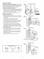
TROUBLESHOOTING
THE SAFETYREVERSINGSENSORS
• Strip 7/16" (11 mm) of insulation from each set of wires.
Separatewhite and white/black wires sufficiently to connect to
the opener quick-connect terminals. Twist like colored wires
together. Insert wires into quick-connect holes: white to white
and white/black to grey (Figure 6).
1. If the sending eyeindicator light does not glow steadily after
installation, check for:
• Electric power to the opener.
• A short in the white or white/black wires. These can occur at
staples, or at opener connections.
ALIGNINGTHE SAFETYREVERSINGSENSORS
• Incorrect wiring between sensors and opener.
• A broken wire.
• Plug in the opener. The indicator lights in both the sending and
receiving eyes will glow steadily if wiring connections and
alignment are correct.
2. If the sending eye indicator light glows steadily but the
receiving eyeindicator light doesn't:
The sending eye amber indicator light will glow regardless of
alignment or obstruction. If the green indicator light in the
receiving eye is off, dim, or flickering (and the invisible light beam
path is not obstructed), alignment is required.
• Checkalignment.
• Checkfor an open wire to the receiving eye.
3. If the receiving eye indicator light is dim, realign either sensor.
NOTE: When the invisible beam path is obstructed or misaligned
while the door is closing, the door will reverse. If the door is
already open, it will not close. The opener lights will blink 10
times. See page 20.
• Loosenthe sending eyewing nut and readjust, aiming directly
at the receiving eye. Lock in place.
• Loosenthe receiving eye wing nut and adjust sensor until it
receivesthe sender's beam. When the green indicator light
glows steadily, tighten the wing nut.
Connect Wire to
Quick-Connect Terminals
Figure 6
Bell Wire
\
Bell Wire
1. Strip wire 7/16"
(11 mm)
17/16"(11 ram) I
2. Twist like colored
wires together
3. To insert or release
wire, push in tab with
screwdriver tip
White Grey
Safety
Reversing
Sensor
Invisible Light Beam
Protection Area
Safety
Reversing
Sensor
Quick-Connect Terminals
22
INSTALLATION
STEP
Fastenthe Door Bracket
12
Fiberglass, aluminum or lightweight steel garage doors WILL
REQUIREreinforcement BEFOREinstallation of door bracket.
Contact your door manufacturer for reinforcement kit.
Follow instructions which apply to your door type as illustrated
below or on the following page.
A horizontal reinforcementbrace shouldbe long enoughto be
securedto two or three vertical supports,A vertical
reinforcementbrace shouldcover the height of the top panel,
Figure 1 shows one piece of angle iron as the horizontal brace.
For the vertical brace, 2 pieces of angle iron are used to create a
U-shaped support. The best solution is to check with your
garage door manufacturer for an opener installation door
reinforcement kit.
NOTE:Many door reinforcement kits provide for direct
attachment of the clevis pin and door arm. In this caseyou will
not need the door bracket, proceed to Step 13.
SECTIONAL
DOORS
1. Center the door bracket on the previously marked vertical
centerline used for the header bracket installation. Note
correct UP placement, as stamped inside the bracket.
Vertical
Centerline of
Garage Door
2. Position the top edge of the bracket 2"-4" (5-10 cm) below
the top edge of the door, OR directly below any structural
support across the top of the door.
3. Mark, drill holes and install as follows, depending on your
door's construction:
HORIZONTALAND VERTICAL
REINFORCEMENTIS NEEDEDFOR
LIGHTWEIGHTGARAGEDOORS
(FIBERGLASS, ALUMINUM, STEEL,
DOORS WITH GLASSPANEL, ETC.).
(NOT PROVIDED)
Figure 1
Metal or light weight doorsusing a vertical angle iron brace
between the door panel supportand the door bracket:
• Drill 3/16" fastening holes. Secure the door bracket using the
two 1/4"-14x5/8" self-threading screws. (Figure 2A)
Vee
' 'c
Vertical
Reinforcement
• Alternately, use two 5/16" bolts, lock washers and nuts (not
provided). (Figure 2B) Metal, insulated or light weight factory
reinforced doors:
o:
• Drill 3/16" fastening holes. Secure the door bracket using the
self-threading screws (Figure 3).
WoodDoors:
eernti
o, ra,',oe
o
• Use top and bottom or side to side door bracket holes. Drill
5/16" holes through the door and secure bracket with
5/16"x2" carriage bolts, lock washers and nuts (not provided).
(Figure 4)
°P
Door Bracket__
_'_..
Lock Washer 5/16"9_.
Nut 5/16"-18
Door Bracket
Self-Threading Screw
1/4"- 14x5/8"
NOTE: The 1/4"-14x5/8" self-threading screws are not intended
for use on wood doors.
Figure 2B
Figure 2A
(Not Provided)
Bolt 5/16"x2"
HARDWARESHOWN
ACTUALSIZE
Screw 1/4"-14x5/8"
- ° - _-_JSelf-Threading
Inside Edge of Door or
Reinforcement Board
Vertical Centerline
of Garage Door
\
Vertical -/_ Self-Threading
"_1_, Screw 1/4"-14x5/8"
Centerline of
Garage Door
Q
Figure4
Figure3
23
ONE-PIECE
DOORS
Please read and comply with the warnings and reinforcement
instructions on the previous page. They apply to one-piece doors
also.
• Center the door bracket on the top of the door, in line with the
header bracket as shown. Mark either the left and right, or the
top and bottom holes.
HARDWARESHOWN
ACTUALSIZE
• Metal Doors: Drill 3/16" pilot holes and fasten the bracket with
the 1/4"-14x5/8" self-threading screws provided.
• WoodDoors: Drill 5/16" holes and use 5/16"x2" carriage bolts,
lock washers and nuts (not provided) or 5/16"x1-1/2" lag
screws (not provided) depending on your installation needs.
Self-Threading Screw
1/4"-14x5/8"
NOTE: Thedoor bracket may be instafled on the top edge of the
door if required for your installation. (Refer to the dotted line
optional placement drawing.)
Header Wall
2x4 Support
--
Finished Ceiling
--
__
'
Door
Bracket
Screw
elf-Threading
1/4"-14x5/8"
Top of Door
(Inside Garage)
Optional
Placement
Door
Bracket
METAL DOOR
Optional
Placement
of Door
Bracket
HORIZONTALAND VERTICAL
REINFORCEMENTIS NEEDED
FOR LIGHTWEIGHTGARAGE
DOORS(FIBERGLASS, ALUMINUM,
STEEL, DOORSWITH GLASS
PANEL, ETC.). (NOT PROVIDED)
Lock
Washer
5/16"
Topof Door
Garage)
Vertical
Centerline of
Garage Door
Top Edge
of Door
Optional
Placement
,
_
For a door with no exposed framing,
or for the optional installation, use
lag screws 5/16"x1-1/2" (Not Provided)
to fasten door bracket.
24
Carriage Bolt
_--
(Not Provided)
5/16"x2"
WOOD DOOR
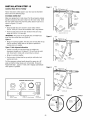
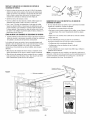
INSTALLATION
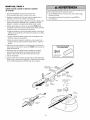
STEP
13
Pulley
Figure 1
ConnectDoorArm to Trolley
/i..
L
8'(20cm)
_-
.
min.__i
,---.je_
f_l
Follow instructions which apply to your door type as illustrated
below and on the following page.
Trolley
stop Bolt
SECTIONALDOORSONLY
......
/
/
Ring
Make sure garage door is fully closed. Pull the emergency release
handle to disconnect the outer trolley from the inner trolley. Slide
the outer trolley back (away from the pulley) about 8" (20 cm) as
shown in Figures 1, 2 and 3.
Fastener
Figure 1:
J I ','r
.....
I I ',_
Tr°lleyl
_ t-'4
I°1
"/_
I°_
I
/
JilJ
/
IolC"__
• Fastenstraight door arm section to outer trolley with the
5/16"x1" clevis pin. Secure the connection with a ring fastener.
v
Trolle.
Clevis Pin
5/16"x1"
Emergency
iol
_
I_1--
Door
Bracket
0
outer
IJ_
Release
P[_ Handle
Straight
Door Arm
Curved Door Arm
• Fastencurved section to the door bracket in the same way,
using the 5/16"x1-1/4" clevis pin.
"
IMPORTANT."Thegroove on the straight door arm MUST face
away from the curved door arm (Figure 4).
Figure 2
Clevis Pin 5/16"x1-1/4"
Pulley
Figure 2:
8" (20 cm) rain. _)1
• Bring arm sections together. Find two pairs of holes that line up
and join sections. Select holes as far apart as possible to
increase door arm rigidity.
Figure 3, Hole alignment alternative:
• If holes in curved arm are above holes in straight arm,
disconnect straight arm. Cut about 6" (15 cm) from the solid
end. Reconnect to trolley with cut end down as shown.
• Bring arm sections together.
• Find two pairs of holes that line up and join with bolts, lock
washers and nuts.
Bolts
Door Bracket
Pull the emergency releasehandle toward the opener at a 45°
angle so that the trolley releasearm is horizontal. Proceedto
Adjustment Step 1, page 27. Trolley will re-engage automatically
when opener is operated.
Pulley
Figure 3
/ iLe"
_.,_--
(20 Cm)rain..__i
_
7,
Trolley /
Stop Bolt
Nuts
_
Lock
//
Washers _/
5/16"
/r,7
/
/o/
"J
-
I
HARDWARESHOWN ACTUALSIZE
5/16"-1_/_
o Qo
Nut 5/16"-18
Clevis Pin
5/16"x1" (Trolley)
Lock Washer 5/16"
Ring Fastener
on
Clevis Pin
5/16"x1-1/4" (Door Bracket)
v
Figure 4
Hex Bolt
5/16"-18x7/8"
CORRECT
(
Door Arm
(Groove
facing out)
25
Cut this end
INCORRECT
ALLONE-PIECEDOORS
CORRECT
INCORRECT
1. Assemblethe DoorArm:
IMPORTANT."Thegroove on the straight door arm MUST face
away from the curved door arm (Figure 5).
• Fastenthe straight and curved door arm sections together to
the longest possible length (with a 2 or 3 hole overlap).
• Make sure the garage door is fully closed. Connect the
straight door arm section to the door bracket with the
5/16"x1-1/4" clevis pin.
• Secure with a ring fastener.
Door
Bracket _
• Pull the emergency release handle, disconnecting the outer
trolley from the inner trolley by pulling straight down on the
emergency release handle and sliding the outer trolley back
toward the motor unit.
_ ._.....,,._._
Ring
,_,,,_'__
|_
__--------__
Fastener
I _
ClevisPin
• Connect the curved door arm section to the trolley using the
5/16"x1-1/4" clevis pin and ring fastener.
Straight
J
_
_
%0"
I
! ___!
I I /I
'_
5/16--18x7/8'
_
_.,__JOurved
DoorArm
• Thetrofley will automatically connect. If not, review the
trolley lockout feature on page 32.
• Whensetting the up limit on the following page, the door
should not havea "backward" slant when fully open as
illustrated below. A slight backward slant will cause
unnecessary bucking and/or jerking operation as the door is
being opened or closed from the fully open position.
Figure 6
Inner Trolley
_._
Emergency Release Handle
Closed
I
5/16"
5/16'x1_n_'__{_/
NOTE:Adjusting the limits on the following page:
I
Nuts
5/16"-18
Lock
Door
Inner Trolley
Outer Trolley
Backward Slant
Open Door
(Incorrect)
26
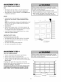
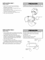
ADJUSTMENT
STEP
1
Program the Travel Limits
Without a properly installed safety reversal system, persons
(particularly small children) could be SERIOUSLYINJUREDor
KILLEDby a closing garage door.
• Incorrect adjustment of garage door travel limits will interfere
with proper operation of safety reversal system.
• NEVERuse force adjustments to compensate for a binding or
sticking garage door.
• After ANY adjustments are made, the safety reversal system
MUST be tested. Door MUST reverse on contact with
1-1/2" (3.8 cm) high object (or 2x4 laid flat) on floor.
Travel limits regulate the points at which the door will stop
when movingup or down.
Figure 1
Black Button
)le Button
Adjust the position of the door by using the black and purple
buttons. Black moves the door UP (open) and purple moves the
door DOWN(close).
To prevent damage to vehicles, be sure fully open door
provides adequateclearance.
Settingthe UP position:
1. Press and hold the black button until the LED starts flashing
slowly, then release.
2. Push and hold the black button until the door reaches the
desired UP (open) position (Figure 2).
Figure 2
LED
t
NOTE:Make sure the door opens high enough for your vehicle.
3. Push the door control or programmed remote control.
This sets the UP (open) limit and begins closing the door
(Figure 3).
until the door
Push
is
at desired
and hold
UP
position
4. Immediately when the door begins to close, press and release
either the black or purple button. This will stop the door.
Settingthe DOWN position:
5. Push and hold the purple button until the door reachesthe
desired DOWN(closed) position (Figure 4).
Figure 3
6. Oncethe door is closed, if there appearsto be too much
pressure on the door, you may toggle the door back and forth
using the black and purple buttons to reach the desired closed
position.
7. Push the door control or programmed remote control
(Figure 3). This sets the DOWN(close) limit and the door
should open.
Proceed to Set the Force.
Figure 4
LED
Push either
button to stop
door at desired
DOWN position
27
ADJUSTMENT
Set the Force
STEP
2
Without a properly installed safety reversal system, persons
(particularly small children) could be SERIOUSLYINJUREDor
KILLEDby a closing garage door.
• Too much force on garage door will interfere with proper
operation of safety reversal system.
• NEVERuse force adjustments to compensate for a binding or
sticking garage door.
• After ANY adjustments are made, the safety reversal system
MUST be tested. Door MUST reverse on contact with
1-1/2" (3.8 cm) high object (or 2x4 laid flat) on floor.
The force setting measuresthe amountof force required to
openand close the door.
1. Push the purple button twice to enter into the Force Adjustment
Mode (Figure 2). The LEDwill flash quickly.
2. Push the door control or programmed remote control. The door
will close (DOWN) (Figure 3).
3. Push the door control or programmed remote control again.The
door will open (UP).
4. Push the door control or programmed remote control a third
time to close the door (DOWN).
The LEDwill stop flashing when the force has been programmed.
Figure 1
The door must travel through a complete cycle, up and down, in
order for the force to be set properly. If the garage door opener
cannot open and close the door fully, inspect the door to ensure
that it is balancedproperly and is not sticking or binding.
If the door is not stopping exactlywhere you would like it, repeat
Program the Travel Limits.
--LED
-- Black Button
- Purple Button
Figure 2
Push Purple button
twice to enter
unit into Force
Adjustment Mode
Figure 3
28
Button
)le Button
ADJUSTMENT
STEP
3
Testthe SafetyReversal System
Without a properly installed safety reversal system, persons
(particularly small children) could be SERIOUSLYINJUREDor
KILLEDby a closing garage door.
TEST
• With the door fully open, place a 1-1/2" (3.8 cm) board (or a
2x4 laid flat) on the floor, centered under the garage door.
• Safety reversal system MUST be tested every month.
• After ANY adjustments are made, the safety reversal system
MUST be tested. Door MUST reverse on contact with
1-1/2" (3.8 cm) high object (or 2x4 laid flat) on the floor.
• Operatethe door in the down direction. The door must reverse
on striking the obstruction.
ADJUST
• If the door stops on the obstruction, it is not traveling far
enough in the down direction. Complete Adjustment Steps 1
and 2.
NOTE: On a sectional door, make sure limit adjustments do not
force the door arm beyond a straight up and down position.
See Figure 3, page 25.
• Repeatthe test.
• When the door reverses on the 1-1/2" (3.8 cm) board (or 2x4
laid flat), remove the obstruction and run the opener through 3
or 4 complete travel cycles to test adjustment.
• If the unit continues to fail the Safety ReverseTest, call for a
trained door systems technician.
IMPORTANTSAFETYCHECK:
Test the Safety ReverseSystem after:
• Each adjustment of door arm length, limits, or force controls.
• Any repair to or adjustment of the garage door (including
springs and hardware).
(or a 2x4 laid flat
• Any repair to or buckling of the garage floor.
• Any repair to or adjustment of the opener.
ADJUSTMENT
STEP
4
Test The ProtectorSysterrP
Without a properly installed safety reversing sensor, persons
(particularly small children) could be SERIOUSLYINJUREDor
KILLEDby a closing garage door.
• Press the remote control push button to open the door.
• Placethe opener carton in the path of the door.
• Press the remote control push button to close the door. The
door will not move more than an inch (2.5 cm), and the opener
lights will flash.
The garage door opener will not close from a remote if the
indicator light in either sensor is off (alerting you to the fact that
the sensor is misaligned or obstructed).
If the opener closesthe door when the safety reversingsensor
is obstructed(and the sensorsare no more than 6" (15 cm)
above the floor), call for a trained door systemstechnician.
SafetyReversingSensor
29
SafetyReversingSensor
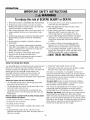
OPERATION
IMPORTANTSAFETYINSTRUCTIONS
iiiiiiiiiiiiiiiiiiiiiiiiiiiiiiiiiiiiiiiiiiiiiiiiiiiiiiiiiiiiiiiiiiiiiiiiiiiiiiiiiiiiiiiiiiiiiiiiiiiiiiiiiiiiiiiiiiiiiiiiiiiiiiiiiiiiiiiiiiiiiiiiiiiiiiiiiiiiiiiiiiiiiiiiiiiiiiiiiiiiiiiiiiiiiiiiiiiiiiiiiiiiiiiiiiiiiiiiiiiiiiiiiiiiiiiiiiiiiiiiiiiiiiiiiiiiiiiiiiiiiiiiiiiiiiiiiiiiiiiiiiiiiiiiiiiiiiiiiiiiiiiiiiiiiiiiiiiiiiiiiiiiiiiiiiiiiiiiiiiiiiiiiiiiiiiiiiiiiiiiiiiiiiiiiiiiiiiiiiiiiiiiiiiiiiiiiiiiiiiiiiiiiiiiiiiiiiiiiiiiiiiiiiiiiiiiiiiiiiiiiiiiiiiiiiiiiiiiiiiiiiiiiiiiiiiiiiiiiiiiiiiiiiiiiiiiiiiiiiiiiiiiiiiiiiiiiiiiiiiiiiiiiiiiiiiiiiiiiiiiiiiiiiiiiiiiiiiiiiiiiiiiiiiiiiiiiiiiiiiiiiiiiiiiiiiiiiiiiiiiiiiiiiiiiiiiiiiiiiiiiiiiiiiiiiiiiiiiiiiiiiiiiii
To reducethe risk of SEVEREINJURYor DEATH:
1. READAND FOLLOWALL WARNINGSAND INSTRUCTIONS.
2. ALWAYS keep remote controls out of reach of children.
NEVERpermit children to operate or play with garage door
control push buttons or remote controls.
3. ONLYactivate garage door when it can be seen clearly, it is
properly adjusted, and there are no obstructions to door
travel.
4. ALWAYS keep garage door in sight until completely closed.
NO ONESHOULDCROSSTHE PATH OFTHE MOVING
DOOR.
5. NO ONESHOULDGO UNDERA STOPPED,PARTIALLY
OPENDOOR.
6. If possible, use emergency releasehandle to disengage
trolley ONLYwhen garage door is CLOSED.Weak or broken
springs or unbalanceddoor could result in an open door
falling rapidly and/or unexpectedly.
7. NEVERuse emergency releasehandle unless garage
doorway is clear of persons and obstructions.
9. If one control (force or travel limits) is adjusted, the other
control may also need adjustment.
10. After ANY adjustments are made, the safety reversal
system MUST be tested.
11. Safety reversal system MUST be tested every month.
Garagedoor MUST reverse on contact with 1-1/2"
(3.8 cm) high object (or a 2x4 laid flat) on the floor.
12. ALWAYS KEEPGARAGEDOOR PROPERLYBALANCED
(see page 3). An improperly balanced door may not
reverse when required and could result in SEVEREINJURY
or DEATH.
13. ALL repairs to cables, spring assemblies and other
hardware, ALL of which are under EXTREMEtension,
MUST be made by a trained door systems technician.
14. To avoid SERIOUSPERSONALINJURYor DEATHfrom
electrocution, disconnect ALL electric and battery power
BEFOREperforming ANY service or maintenance.
is SAVETHESEINSTRUCTIONS.
8. NEVERuse handle to pull garage door open or closed. If
rope knot becomes untied, you could fall.
Using Your Garage Door Opener
Your Security÷ ® opener and hand-held remote control have been
factory-set to a matching code which changes with each use,
randomly accessing over 100 billion new codes. Your opener will
operate with up to ten Security÷ ® remote controls, one
Security+ ® KeylessEntry System, and one accessory wall
control. If you purchase a new remote, or if you wish to
deactivate any remote, follow the instructions in the Programming
section.
6. If obstructed while opening, the door will stop.
Activateyour opener with any of the following:
• The Hand-Held Remote Controh Hold the large push button
down until the door starts to move.
The opener lights will turn on under the following conditions:
when the opener is initially plugged in; when power is restored
after interruption; when the opener is activated.
• The Wall-Mounted Door Controh Hold the push button or bar
down until the door starts to move.
They will turn off automatically after 4-1/2 minutes or provide
constant light when the Light feature on the door control is
activated. Bulb size is A19. Bulb power is 100 watts maximum.
• The KeylessEntry (seeAccessories): If provided with your
garage door opener, it must be programmed before use. See
Programming.
Whenthe opener is activated (with the safety reversingsensor
correctly installed and aligned)
1. If open, the door will close. If closed, it will open.
2. If closing, the door will reverse.
3. If opening, the door will stop.
7. If fully open, the door will not close when the beam is broken.
The sensor has no effect in the opening cycle.
If the sensor is not installed, or is misaligned, the door won't
close from a hand-held remote. However, you can close the door
with the door control, the Outdoor Key Switch, or KeylessEntry, if
you activate them until down travel is complete. If you release
them too soon, the door will reverse.
Security4.° light feature: Lights will also turn on when someone
walks through the open garage door. With a Smart Control
Panel®, this feature may be turned off as follows: With the opener
lights off, press and hold the light button for 10 seconds, until the
light goes on, then off again. To restore this feature, start with the
opener lights on, then press and hold the light button for 10
seconds until the light goes off, then on again.
4. If the door has been stopped in a partially open position, it will
close.
5. If obstructed while closing, the door will reverse. If the
obstruction interrupts the sensor beam, the opener lights will
blink for five seconds.
3O
Usingthe Wall-MountedDoor Control
feature, press
THE SMART CONTROLPANEL
®
Press the push button
to open or close the
door. Press again to
reverse the door during
the closing cycle or to
stop the door while it's
opening.
Offdisable
button on
control.
thisthe left side of the
thedoor
Automatic
On/
We recommend that you disable the motion sensor
when using the opener lights as working lights. Otherwise, they
will turn off automatically if you are working beyond the sensor's
range.
_To
_._z
L
Push Bar
Motion Detecting
Light On/Off
Prog <Learn>
Hour
PROG<Learn> Feature
Minute --
The door control is equipped with a PROG<LEARN>button to
assist in learning remote controls to the unit. Press the PROG
<LEARN>button once to initiate LEARN mode and the display will
show 'Learn Remote Control - Press Learn Button Again to
Confirm.' Press the PROG<LEARN>button a second time and
the display will show 'Learn Mode - Press Remote Control Button
to Learn Remote.' Press the button of the remote control to be
learned and the worklight will blink to confirm the remote control
has been learned.
Language _i
This door control
contains a motion
Degrees (F/C) J
_
LightButton
detector that will
\ Lock Button
automatically turn on
the light when it detects
a person entering the garage. This feature can be easily turned off
for extended work light use.
HT
Light
Light Feature
H--_--M
Hour and Minute Feature
Press or hold either of these side buttons to
increment the hour or minute displayed on the LCD display.
v
Press the Light button to turn the opener light on or off. It will not
control the opener lights when the door is in motion. If you turn it
on and then activate the opener, the light will remain on for 4-1/2
minutes. Press again to turn it off sooner. The 4-1/2 minute
interval can be changed to 1-1/2, 2-1/2, or 3-1/2 minutes as
follows: Press and hold the Lock button until the light blinks
(about 10 seconds). A single blink indicates that the timer is reset
to 1-1/2 minutes. Repeatthe procedure and the light will blink
twice, resetting the timer to 2-1/2 minutes. Repeat again for a
3-1/2 minute interval, etc., up to a maximum of four blinks and
4-1/2 minutes. When using the opener lights as working lights, we
recommend that you first disable the motion sensor.
<LANG>LanguageFeature
Press this side button to toggle between the three languagesEnglish, Spanish, and French.
Degrees F/C Feature
Press th s s de button to toggle the temperature units
between Fahrenheitand Celsius.
f'h
LOC
[_]K
Additional feature when used with the 3-Button
hand-held remote
To control the opener lights:
LockFeature
Designed to prevent operation of the door from
hand-held remote controls. However, the door will open and close
from the door control, the outdoor key switch and the keyless
Entry accessories.
1. With the door closed, press and hold a small remote button
that you want to control the light.
2. Press and hold the Light button on the door
control.
To activate, press and hold the Lock button for 2 seconds.
To turn off, press and hold the Lock button again for 2 seconds.
The Lock feature will also turn off whenever the "learn" button on
the motor unit panel is activated.
3. While holding the Light button, press and
hold the Lock button on the door control.
4. After the opener lights flash, releaseall buttons.
Motion Detecting Light Feature:The opener light will turn on
automatically when a person walks in front of the wall-mounted
door control. This feature works by detecting motion and body
heat and may not work in temperatures around 100°F(37.7° C).
The opener light will come on for 5 minutes, then shut off
automatically if no additional motion or heat differential is
calculated.
31
THE REMOTECONTROLBATTERY
Care of YourOpener
MAINTENANCESCHEDULE
Oncea Month
To prevent possible SERIOUSINJURYor DEATH:
• NEVERallow small children near batteries.
• If battery is swallowed, immediately notify doctor.
• Manually operate door. If it is unbalancedor binding, call a
trained door systems technician.
• Checkto be sure door opens and closes fully. Adjust limits
and/or force if necessary (see pages 27 and 28).
To reduce risk of fire, explosion or chemical burn:
• ReplaceONLYwith 3V2032 coin batteries.
• DONOT recharge, disassemble, heat above 212° F (100° C)
or incinerate.
• Repeat the safety reversetest. Make any necessary
adjustments (See Adjustment Step 3).
Oncea Year
• Oil door rollers, bearings and hinges. The opener does not
require additional lubrication. Do not greasethe door tracks.
The lithium battery should produce
power for up to 5 years.
To replace battery, use the visor clip or
screwdriver blade to pry open the case
as shown. Insert battery positive
side up (+).
Open this end
,,,,,,_
first to avoid/_(....._
cracking _
q_L__/
j-_
hous_
Dispose of old battery properly.
Replace the battery with only
3V2032 coin cell batteries.
NOTICE:To comply with FCCand or Industry Canadarules (IC),adjustment or modifications of this
receiver and/or transmitter are prohibited, except for changing the code setting or replacing the
battery.THEREARE NOOTHERUSERSERVICEABLEPARTS.
Tested to Comply with FCCStandards FOR HOMEOR OFFICEUSE, Operation is subject to the
following two conditions: (1) this device may not cause harmful interference, and (2) this device
must acceptany interference received,including interferencethat may cause undesiredoperation,
To Openthe Door Manually
Trolley
DISCONNECTTHE TROLLEY
The door should be fully closed if
possible. Pull down on the
emergency releasehandle (so that
the trolley releasearm snaps into a
vertical position) and lift the door
manually. The lockout feature
prevents the trolley from
reconnecting automatically, and the
door can be raised and lowered
manually as often as necessary.
Trolley -Release Arm
(In Manual
Disconnect
Position)
To prevent possible SERIOUSINJURYor DEATHfrom a falling
garage door:
• If possible, use emergency releasehandle to disengage
trolley ONLYwhen garage door is CLOSED.Weak or broken
springs or unbalanceddoor could result in an open door
falling rapidly and/or unexpectedly.
• NEVERuse emergency releasehandle unless garage doorway
is clear of persons and obstructions.
_
• NEVERuse handle to pull door open or closed. If rope knot
becomes untied, you could fall.
Lockoutposition
(Manual disconnect)
TO RE-CONNECTTHE TROLLEY
Trolley
Pull the emergency release handle
toward the opener at an angle so
that the trolley releasearm is
horizontal. The trolley will reconnect
on the next UP or DOWNoperation,
either manually or by using the door
control or remote.
".
_. Arm
Emergency
"'_
Release Handle _ ",_.._
(Down and Back)_:_'
W
TOreconnect
32
Battery Backup
OPERATINGINSTRUCTIONS
To test the battery, disconnect the motor unit power cord from
the electrical outlet.
To reduce the risk of FIREor INJURY to persons:
• DisconnectALL electric and battery power BEFORE
performing ANY service or maintenance.
• Use ONLY Craftsman part #41B822 for replacementbattery.
• A solid orange LED indicates the battery is operating on battery
power.
• DONOT dispose of battery in fire. Battery may explode.
Check with local codes for disposal instructions.
1. Test the installed battery with the motor unit.
• A flashing orange LEDwith beep indicates the unit is operating
on battery power and that the battery charge is low.
• To test the battery is functioning properly, open and close the
garage door.
• Re-connect the motor unit power cord back into the electrical
outlet.
• Verify that the green LEDis flashing on the BBU(indicates that
the battery is now charging).
• Test completed.
Battery
Status LED
2. Chargethe battery.
• Batterywill take 24 to 48 hours to fully charge.
A fully charged battery supplies 12 Vdc to the motor unit for one
to two days of normal operation during an electrical power
outage. If the battery voltage drops too low, the batteries will
disconnect and the motor unit will no longer operate under
battery power.
NOTE: LEDis most visible with worklight off.
GREENLED:
Aft systems are normal
After the electrical power has been restored, the battery will
recharge within 48 hours. Under normal usage batteries will last
3 to 5 years.
• A solid LEDlight indicates the battery is fully charged.
• A flashing LEDindicates the battery is being charged.
NOTE: Battery does not have to be fully charged to operate the
motor unit.
To obtain maximum battery life and prevent damage,
disconnectthe battery when the motor unit is unpluggedfor an
extendedperiod of time.
ORANGELED:
NOTE: Door operation may be limited until battery is fully
charged. The motor unit's lights will not turn on during battery
mode.
Themotor unit has lost power and is operating off of the battery.
• A solid LEDwith beep, sounding approximately every 2
seconds, indicates the motor unit is activating the door and is
operating off of the battery.
• A flashing LEDwith beep, sounding every 30 seconds,
indicates battery is low.
• Once the power is restored the battery will recharge. This is
indicated by a flashing green LED.
RED LED:
• If a red LED remains on when the power is restored, and is
accompanied by a beep sounding every 30 seconds, please call
for service.
• To obtain maximum battery life and prevent damage, also
disconnect the battery if you unplug the motor unit while on
vacation or any other extended period of time.
Battery
Door
33
Having a Problem (Troubleshooting)
NOTE: Always unplug battery prior to troubleshooting.
Bell Wire
1. My door will not close and the light bulbs blink on my motor
unit: The safety reversing sensor must be connected and
aligned correctly before the garage door opener will move in
the down direction.
• Verify the safety reversing sensors are properly installed,
aligned and free of any obstructions. Refer to Installation
Step 11: Install TheProtector System®.
• Check diagnostic LED for flashes on the motor unit then refer
to the Diagnostic Chart on the following page.
"Learn"
Button LED
2. My remotes will not activate the door:
or Diagnostic
• Verify your Smart Control Panel® does not display "Lock
Mode." If it does, deactivate the Lock Mode following the
instructions for Using the Smart Control PaneP.
)
J
Safety Reversing Sensor
• Reprogram remotes following the programming instructions.
Refer to Programming.
Sending Eye Safety
Reversing Sensor
(Amber Indicator Light)
• If remote will still not activate your door, check diagnostic
LED for flashes on motor unit then refer to Diagnostic Chart
on the following page.
3. My door reversesfor no apparent reason: Repeat safety
reversetest after adjustments to force or travel limits. The need
for occasional adjustment for the force and limit settings is
normal. Weather conditions in particular can affect door travel.
Receiving Eye Safety
Reversing Sensor
(Green Indicator Light)
• Run the motor unit from the remote control or door control.
The trolley should travel towards the door and stop. If the
trolley re-engageswith the door, pull the Emergency Release
Rope to disengage.
• Manually check door for balanceor any binding problems.
• Refer to Adjustment Step 2, Set the Force.
4. My door reversesfor no apparent reason after fully closing
and touchingthe floor: Repeatsafety reverse test after
adjustments to force or travel limits.The need for occasional
adjustment for the force and limitsettings is normal. Weather
conditions in particular can affect door travel.
• Refer to Adjustment Step 1, Program the Trave/Limits.
• Re-Tighten the outer nut until the trolley spring is
approximately 1-1/4" (3.18 cm) in length.
5. My lights will not turn off when door is open:
• The garage door opener is equipped with a security light
feature. This feature activates the light on when the safety
reversing sensor beam has been obstructed. Refer to
Operation section; Using the Smart Control PaneP, Light
Feature.
• If the trolley does not move away from the bolt, repeat the
steps above.
7. Batterystatus LED is not lit properly:
• Check battery connections.
6. My motor unit hums briefly:
• First verify that the trolley is against the stop bolt.
8. My garage door opener beeps:
• Releasethe door from the opener by pulling the Emergency
Release Rope.
• Manually bring the door to a closed position.
• A solid LED with beep, sounding approximately every
2 seconds, indicates the motor unit is activating the door
and is operating off of the battery.
• Loosen the belt by adjusting the outernut4 to 5 turns. This
relieves the tension.
• A flashing LEDwith beep, sounding every 30 seconds,
indicates battery is low.
• If a red LED remains on when the power is restored, and is
accompanied by a beep sounding every 30 seconds,
replace the battery.
34
I L
Yourgarage door opener is programmed with serf-diagnostic
capabilities. The "Learn" button/diagnosticLED wi// f/ash a
number of times then pause signifyingit has found a potential
issue. ConsultDiagnostic Chartbelow.
DiagnosticChart
•
Safety reversingsensors
wire open (brokenor
disconnected).
OR
Safety reversingsensorswire
shortedor black/whitewire
reversed.
Symptom:Oneor bothof the Indicatorfights on the safety reversingsensorsdo not
glowsteady.
• Inspect sensor wires for a short (staple in wire), correct wiring polarity (black/white wires
reversed), broken or disconnected wires, replace/attachas needed
• Disconnect all wires from back of motor unit
• Remove sensors from brackets and shorten sensor wires to 1-2 ft (30-60 cm) from back
each of sensor.
• Reattach sending eye to motor unit using shortened wires. If sending eye indicator light
glows steadily, attach the receiving eye.
• Align sensors, if the indicator lights glow replace the wires for the sensors. If the sensor
indicator lights do not light, replacethe safety reversing sensors.
•.0 Symptom:LEDis not lit on door control.
Door controlor wire shorted.
• Inspect door control/wires for a short (staple in wire), replace as needed.
• Disconnect wires at door control, touch wires together. If motor unit activates, replace
door control.
• If motor unit does not activate, disconnect door control wires from motor unit. Momentarily
short across red and white terminals with jumper wire. If motor unit activates, replacedoor
control wires.
•.• Symptom:Sendingindicator fight glows steadily, receivingindicator fight is dim or
Safety reversingsensors
slightly misaligned
(dim or flashingLED).
flashing.
• Realign receiving eye sensor, clean lens and secure brackets.
• Verify door track is firmly secured to wall and does not move.
•.• Symptom:Door travels 2-3 inches and stops.
Motor RPM is not recognized.
• Reprogram limits and forces. See Adjustment section.
• If the motor unit continues to travel 2-3 inches, check the travel module connection or
replace the travel module.
Symptom: No movement, motor runs2-3 seconds.
• Reconnect the emergency release.
• Motor may need to be replaced.
35
Smart ControlPanel®Messages
The following messages are contained within the Smart Control
Panel® and may appear during the operations of the unit:
•4) Meaning: Thismessage will appear if the Safety ReversingSensorsare out of alignment, if they
are blockedor if the wiring is disconnected.To clear messagefrom doorcontroldo the following:
SAFETYSENSORSCHECK
• Checkto see that area is clear between the safety reversing sensors.
ALIGNMENT,BLOCKAGE
• Checkto see that the safety reversing sensors are not misaligned.
OR IVIISWIRINGSEE
• Realign receiving eye sensor, clean lens and secure brackets.
OWNER'SMANUAL
• Verify door track is firmly secured to wall and does not move.
• Checkto see that the safety reversing sensors' wires are connected to the motor unit.
• If message has not cleared after the above checks, refer to message#2.
SAFETYSENSORS
MALFUNCTIONCHECK
IVIISWIRINGSEE
OWNER'SMANUAL
LEARNREMOTE
CONTROLPRESS
LEARNBUTTON
TO CONFIRM
LEARNMODE PRESS
REMOTECONTROL
BUTTONTO PROGRAM
REMOTE
LOCKMODE REMOTE
CONTROLLOCKEDOUT
PRESSLOCKBUTTONTO
ENABLEREMOTE
ENGLISH,FRAN_AIS
AND ESPANOL
•"0 Meaning: Thismessage will appear if the safety reversingsensorsare miswired.
Toclear the message, do the following:
• Inspect the safety reversing sensor wires for a short (staple in wire), correct wiring polarity
(black/white wires reversed), replace/attachas needed.
• Disconnect all wires from back of motor unit.
• Remove safety reversing sensors from brackets and shorten sensor wires to 1-2 ft. (30-60 cm)
from back of each sensor.
• Reattach sending eye to motor unit using shortened wires. If sending eye indicator light glows
steadily, attach the receiving eye.
• Align sensors, if the indicator lights glow replace the wires for the sensors. If the sensor indicator
lights do not light, replacethe safety reversing sensors.
•"0 Meaning: Thismessage will appear when the *LEARN'buttonhas been pressed on the door
control Pressingthe *LEARN'buttonagain will allow the user to programan additional remote
controlto the opener.
•"0 Meaning: Thismessage will appear when the *LEARN'buttonhas been presseda second time on
the doorcontrol or anytime on the opener. The opener is ready to program another remote
controlby simplypressing the remote controlbutton. Oncethe opener has *LEARNED'the remote
control, the work/ight will blink one time.
•"0 Meaning: Thismessage will appear when the *LOCK'buttonhas been pressed and held for more
than one second. Thisfeature will disable the opener from receiving remote controlsignals. To
exit *LOCK'mode, press and hold the buttonfor more than one second.
•"0 Meaning: Thismessage will appear when the *LANGUAGE'buttonhas been pressed. Pressing
the button will toggle to the next language.
•"•
MOTIONSENSINGON
MOTIONSENSINGOFF
Meaning: Thismessage will appear when the Motion Sensing buttonis pressed. The motion
detectorwill toggle on or off with each press of the button.
36
PROGRAMMING
NOTICE:/f this Security,F_ garage door opener is operated with a non-rolling code transmitter, the technical measure in the receiver of
the garage door opener, which provides security against code-theft devices, will be circumvented. Theowner of the copyright in the
garage door opener does not authorize the purchaser or suppfier of the non-rolling code transmitter to circumvent that technical
measure.
Your garage door opener has already been programmed at the factory to operate with your hand-held remote control. The door will
open and close when you press the large push button.
Below are instructions for programming your opener to operate with additional Security+ ® 315 MHz remote controls.
To Add or Reprogram a Hand-he/d Remote Contro/
USINGTHE "LEARN" BUTTON
USINGTHE DOORCONTROL
1. Pressand releasethe "learn" button on
the motor unit. The learn LEDwill glow
steadilyfor 30 seconds.
1. Pressthe Learn button on the door control.
2. Pressthe Learn button again to confirm
Learn Mode.
2. Within 30 seconds,press and hold the
button on the hand-heldremote*that you
wish to operateyour garagedoor.
3. Pressthe button on the hand-heldremote*that
you wish to operateyour garagedoor.
3. Releasethe button whenthe motor unit
lights blink. It has learnedthe code. If
light bulbs are not installed,two clicks
will be heard.
\l/
4. Whenthe motor unit lights blink, it has learned
the code. If light bulbs are not installed,two
clicks will be heard.
To Erase A// Codes From Motor Unit Memory
\1
*3-Button Remotes (315 MHz)
To deactivate any unwanted remote, first
erase all codes:
If provided with your garage
door opener, the large button
is factory programmed to
operate it. Additional buttons
on any Security-I.® 3-Button
remote or compact remote can
be programmed to operate other Security-I-® garage door
openers.
Press and hold the purple "learn" button on
motor unit until the learn LEDgoes out
(approximately 6 seconds). All previous
codes are now erased. Reprogram each
remote or keyless entry you wish to use.
37
/
To Add, Reprogram or Change a Key/ess Entry PIN
NOTE: Your new KeylessEntry must be programmed to operate your garage door opener.
USINGTHE "LEARN" BUTTON
USINGTHE DOORCONTROL
I
NOTE: Thismethod requirestwo people if the KeylessEntry is
alreadymounted outside the garage.
1. Pressand releasethe "learn" button on
motor unit. The learn LEDwill glow
steadilyfor 30 seconds.
1. Pressthe Learn button on the door control.
2. Within 30 seconds,enter a four digit
personalidentificationnumber (PIN) of
your choice on the keypad.Then press
and hold the ENTERbutton.
3. Releasethe button whenthe motor unit
lights blink. It haslearnedthe code. If
light bulbsare not installed,two clicks
will be heard.
2. Pressthe Learn button again to confirm
Learn Mode.
\1/
3. Entera four digit personalidentification
number (PIN) of your choice on the keypad.
Thenpress ENTER.
To changean existing, knownPIN
4. Whenthe motor unit lights blink, it has
learnedthe code. If light bulbs are not
installed,two clicks will be heard.
If the existing PIN is known, it may be changedby one person
without usinga ladder.
1. Pressthe four buttons for the presentPIN,then pressand hold
the # button.
Theopener light will blink twice. Releasethe # button.
2. Pressthe new 4-digit PIN you havechosen,then press ENTER.
The motor unit lights will blink oncewhenthe PIN has been learned.
2. Pressthe temporary 4-digit PIN you havechosen,then press
ENTER.
Test by pressingthe new PIN,then press ENTER.The door should
move.
3. To set the number of hol/rsthistemporary PIN will work, press
the number of hours (up to 255), then press _.
Theopener light will blink four times.
To set a temporaryPIN
You mayauthorizeaccess by visitors or servicepeoplewith a
temporary 4-digit PIN.After a programmed numberof hours or
number of accesses,this temporary PIN expiresand will no longer
open the door. It can be usedto closethe door evenafter it has
expired.To set a temporary PIN:
1. Pressthe four buttons for your personalentry PIN (not the last
temporary PIN),then press and hold the • button.
Theopener light will blink three times. Releasethe button.
OR
3. To set the number of timesthistemporary PIN will work, press
the number of times (up to 255), then press #.
The opener light will blink oncewhenthe temporary PIN has been
learned.
Test by pressingthe four buttons for the temporary PIN,then press
ENTER.The door should move. If the temporary PINwas set to a
certain numberof openings,rememberthat the test has usedup one
opening.To clearthe temporarypassword, repeatsteps 1-3, setting
the numberof hours or times to 0 in step 3.
OneButtonClose:Openercan be closedby pressing only the ENTERbutton if the one button close featurehas beenactivated.This feature
has beenactivatedat the factory. Toactivateor deactivatethis featurepress and hold buttons 1 and 9 for 10 seconds. Thekeypad will blink
twice whenthe one button close is active. Thekeypadwill blink four times whenone button close is deactivated.
38
REPAIR
PARTS
Rail Assembly Parts
3
KEY
NO.
Installation Parts
PART
NO.
DESCRIPTION
1
4A1008
Master link kit
2
3
4
5
6
7
41C5141-2
41C5665-2
41B4103-1
144C54
41A5250
12D598-1
Completetrolley assembly
Complete rail
Spring trolley nut
Idler pulley
Full belt assembly
"U" bracket
NOT SHOWN
183A163
Wear pads
_[
KEY
NO.
PART
NO.
DESCRIPTION
41A6317
41A6140-1
Smart Control PaneP
3
10A20
3V2032 Lithium battery
4
29B137
Visor clip
5
41D543-1
Keyless entry keypad cover
6
41D541
Keyless entry battery cover
7
41A2828
8
41B4494-1
Emergencyreleaserope and handle assembly
2-Conductor bell wire: white and white/red
1
2
3-Button remote control case
(no circuit board)
9
41A5047-3
Headerbracket with clevis pin and fastener
10
41A5047-1
11
178B35
Door bracket with clevis pin and fastener
Curved door arm section
12
178B34
Straight door arm section
13
12B776
Hanging bracket
14
41A5034
Safety reversing sensor kit (receiving and
sending eyes) with 3' (.9 m) 2-conductor bell
wire attached
15
16
41A5266-1
41B822
Safety reversing sensor bracket
101D165
Push bar for door control
41A5257-17
Installation hardware bag
(includes hardware listed on page 7)
Owner's manual
114A4283
1
39
Battery
NOTSHOWN
Motor UnitAssemblyParts
2
10
6
10
9
KEY
NO.
PART
NO.
DESCRIPTION
1
2
3
41A537
41B4245
41B4375-3
Belt cap and pulley
Line cord
4
5
6
7
41A6281
41D843
41DB102-2
41A6268
Wire harness kit
Terminal block with screws
KEY
NO.
8
9
10
11
PART
NO.
DESCRIPTION
41C190
41D503-2
Transformerand harness
Cover
108D77
175B88
Lightlens
Lightsocket
Motor with travel module
NOTSHOWN
Receiver logic assembly
41B822
End panel with battery door
and screw
4O
Batterykit
ACCESSORIES
139.53702
EmergencyKeyRelease:
139.53589
Required for a garage with NO access
door. Enableshomeowner to open garage
door manually from outside by
disengaging trolley.
139.53728
For finished ceilings or where additional
support is required, based on garage
construction. Includes brackets and
fastening hardware.
139.53753
8 Foot(2.4 m) Rail Extension:
To allow a 8 foot (2.4 m) door to open
fully.
139.53729
139.53752
10 Foot(3 m) Rail Extension:
SECURITY+®3-Button Compact
Remote Control:
With loop for attaching key ring.
139.53754
ExtensionBrackets:
(Available onlythrough SearsParts &
Service)
(Optional) For safety reversing sensor
installation onto the wall or floor.
139.53709
SECURITY+®3-Button Remote Control:
Includes visor clip.
To allow a 10 foot (3 m) door to open
fully.
41A5281
SupportBrackets:
41A6344
SECURITY+® KeylessEntry:
Enableshomeowner to operategarage door
opener from outside by entering a password.
Also can add a temporary passwordfor
visitors or service persons.
Wireless Door Control:
(Available only throughSears Parts &
Service)
One button door control for additional
control panel.
Door Clearance Brackets:
(For Sectional DoorsOnly)
Replacestop brackets and rollers on door
to reduce height of door travel. For use
when installingopener in garage with low
headroom clearance.
139.53749
Plug-In Light Control:
Enableshomeowner to turn on a lamp,
television or other appliance from car,
bedside, or anywhere in the home with a
remote.
WARRANTY
CRAFTSMAN GARAGE DOOR OPENER LIMITED WARRANTY
90-DAY IN-HOME FULL WARRANTY ON PRODUCT
For 90 days from the date of purchase, this product will be repaired, free of charge, if defective in material or workmanship.
ADDITIONAL LIMITED WARRANTY ON PARTS
From the 91st day up to 3 year from the date of purchase, replacement parts for any defective parts on this product will be furnished, free of charge. You pay for labor.
10-YEAR LIMITED WARRANTY ON MOTOR
From the 91st day and through 10 years, if the motor on this product is defective, a replacement motor will be furnished free of charge. You pay for labor.
WARRANTY RESTRICTION
This Craftsman Garage Door Opener Limited Warranty does not cover light bulbs or repair parts necessary because of operator abuse or negligence, including the failure to install, adjust
and operate this garage door opener according to instructions contained in the owner's manual. This limiled warranly also does not cover any problems caused by interference.
LIMITATION ON LIABILITY
Seller will not be liable for loss or damage to property or any incidental or consequential loss or expense from property damage due directly or indirectly to the use of this product. Some
states do not allow the exclusion or limitation of incidental or consequential damages, so the above limitation or exclusion may not apply to you.
DISCLAIMER OF IMPLIED WARRANTIES
Except for the motor, all implied warranties for this product, including but not limited to any implied warranties of merchantability and fitness for a particular purpose, are limited in
duration to the 91st day through 3-year limited warranty period set forth above. All implied warranties with respect to the motor are limited in duration to the 91st day through 10-year
limited warranty period set forth above. No implied warranties will exist or apply after such periods. Some States do not allow limitations on how long an implied warranty lasts, so the
above limitations may not apply to you.
FROM THE 91ST DAY, WARRANTY SERVICE IS AVAILABLEBY SIMPLY CONTACTINGTHE NEARESTSEARSSTORE OR SEARS SERVICE CENTERIN
THE UNITED STATES.
WARRANTY SERVICE IS AVAILABLEBY CALLING 1-800-4-MY-HOME _.
This warranty applies only while this product is in use in the United States.
This warranty gives you specific legal rights, and you may also have other rights which vary from state to state.
Sears, Roebuck and Co., Dept. 817WA, Hoffman Estates, IL 60179
41
CONTENIDO
Introducci6n
2-7
Ajustes
27-29
Revisi6n de los simbolos y t_rminos de seguridad .................
2
Ajuste el limite del recorrido ..................................
27
Preparaci6n de la puerta de su cochera ..........................
Herramientas necesarias......................................
3
3
Ajuste lafuerza ............................................
28
Pruebe el sistema de retroceso de seguridad .....................
29
Pruebe La Protector System®.................................
29
Planificaci6n ............................................
4-5
Inventario de la caja de cart6n .................................
6
Inventario de piezas .........................................
7
Operaci6n
30-36
Instrucci6nes importantes de seguridad .........................
30
8-11
C6mo usar su abridor de puerta de cochera......................
30
Monte el riel y instale el trole ..................................
8
C6mo usar la control de la puerta de pared ......................
31
Fije el riel a la unidad del motor ................................
9
Mantenimiento de su abridor de puerta de cochera ................
32
Instale la polea Ioca .........................................
9
Cdmo abrir la puerta manualmente ............................
32
33
Montaje
Instale la banday sujete el ret_n de la cubierta de la banda .........
10
Reserva de bateria .........................................
Fije la tensi6n de la banda....................................
11
Si tiene alg_n problema (Diagndstico de fallas) ...................
34
Tabla de diagndstico ........................................
35
Mensajes de la Smart Control PaneP ...........................
36
Instalaci6n
11-26
Instrucci6nes importantes para la instalaci6n.....................
11
Determine d6nde va a instalar la m_nsula del cabezal ..............
12
C6moProgramarel Abridor
Instale la m_nsula del cabezal.................................
13
C6mo agregar o reprogramar un control remoto manual............
Coloque el riel en la m_nsula del cabezal........................
14
Coloque el abridor en posici6n ................................
15
Para borrar todos los c6digos de la memoria de la unidad la motor ...37
Controles remotos de 3 botones ..............................
37
Cuelgue el abridor ..........................................
16
Instale la control de la puerta .................................
Instale la bateria ...........................................
17
18
Instale las luces ...........................................
Instale la manija y la cuerda de emergencia ......................
Requisitos para la instalaci6n el_ctrica ..........................
19
37-38
37
C6mo agregar, reprogramar o cambiar un c6digo de entrada
sin Ilave..................................................
38
Accesorios
39
18
Garantia
39
18
N#meros de Servicio
Instale La Protector System_ ..............................
20-22
Fije la m_nsula de la puerta ...............................
23-24
Conecte el brazo de la puerta al trole ........................
25-26
Contratapa
INTRODUCCION
Revisi6n de los simbolosy t_rminosde seguridad
Este abridor de puerta de cochera ha sido diseSadoy probado para un funcionamiento seguro, siempre y cuando se instale, se pruebe, se opere y se
le d_ mantenimiento como se indica en este manual, cumpliendo al pie de la letra con todas las advertencias e instrucciones generales aqui
contenidas.
Mecanica
El_ctrica
Estas advertencias y/o simbolos de seguridad que aparecen en este
manual le alertar_.nde que existe el riesgo de una lesi6n seria e de
muerte si no se siguen las instrucciones correspondientes. El peligro
puede ser el_ctrico (electrocuci6n) o mec_.nico.Lea las instrucciones con
mucho cuidado.
Cuando vea esta palabra y/o simbolo de seguridad en este manual, le
alertar_,de que existe el riesgo de da_ar la puerta de la cocheray/o el
abridor si no se siguen las instrucciones correspondientes. Lea las
instrucciones con mucho cuidado.
Preparaci6nde/a puerta de su cochera
Antes de comenzar:
Para evitar una LESIONGRAVEo INOLUSOLA MUERTE:
• Quite los seguros.
• SIEMPRE Ilame a un t_cnico profesional para que le d_ servicio a su
puerta de cochera si _sta se atora, se pandea o est,. desbalanceada.
Una puerta de cochera que no est_ bien balanceadapuede que no
retroceda como se requiere.
• Retire cualquier cuerda o cable que est_ conectado a la puerta.
• Haga la siguieate prueba con su puerta para verificar que est_
balanceaday que no se atore ni se pandee:
• NUNCAintente aflojar, mover ni ajustar la puerta de su cochera, los
resortes de la puerta, los cables, las poleas, las m_nsulas ni la
tornilleria, puesTODOSestos elementos est_.nbajo tensi6n
EXTREMA.
1. Levante la puerta hasta la mitad de su recorrido como se muestra.
Suelte la puerta. Si est,. balanceada,deber_,mantenerse en esa
posicidn con s61oel soporte de los resortes.
2. Suba y baje la puerta; observe si se atora con algo o si se pandea.
• Quite TODOSlos seguros y retire TODASlas cuerdas conectadas a
la puerta de cochera ANTESde instalar y operar el abridor de la
puerta de cochera para evitar que se enreden.
Si su puerta se atora o se pandea, o no est,. balanceadaIlame a un
t_cnico especializadoen sistemas de puertas.
Para evitar que se daffen el puerta y el abridor:
• SIEMPRE quite los seguros ANTESde instalar y/o de operar el
abridor.
• SOLAMENTEopere el abridor de puerta de cochera con corriente de
120V, 60Hz con objeto de evitar su mal funcionamiento y que el
abridor se daffe.
Puertaseccional
Puertade unasola pieza
Herramientasnecesarias
Durante el montaje, instalaci6n y ajuste del abridor, las instrucciones le
indicar_.nc6mo usar las herramientas que aparecen en la siguiente
ilustraci6n.
L_piz
Sierra de mano
Cinta de medir
Oortadora de alambre
Taladro
Brocas de 3/16, 5/16
y 5/32 de pulgada
Escalera
NO
7/16, 9/16 y 1/4 de p'ulgada
Destornillador
Llave inglesa
Planificaci6n
Identifique la altura y el tipo de su puerta de cochera. Reviseel _.reade
su cochera y observe si alguna de las siguientes instalaciones
corresponden ala suya. A veces se requieren materiales adicionales, asi
que tal vez sea conveniente tener esta hoja y las ilustraciones
correspondientes a mano cuando inicie la instalaci6n de su abridor.
Dependiendo de sus necesidades individuales, es posible queen algunos
casos vaya a necesitar materiales o herramientas que no se incluyen con
este producto.
•
Instalaci6n Paso 1 - Observe la pared o el cielo raso justo por encima
de la puerta de la cochera. La m_nsula del cabezaldebe estar
firmemente sujeta a los soportes de la estructura.
•
Instalaci6n Paso 5 - Si el plaf6n o cielo raso de su cochera tiene
acabado, es posible que necesite una m_nsula de soporte y/o m_.s
pernos y tornilleria para la instalaci6n.
•
Instalaci6n Paso 11 - Dependiendodel tipo de construcci6n de su
cochera, es posible que necesite m_nsulas de extensi6n o bloques de
madera para instalar los sensores.
•
Observe el punto donde la puerta hace contacto con el piso. El
espacio entre la basede la puerta y el piso no debe exceder 6 mm
(1/4 de pulgada). Si no es asi, se corre el riesgo de que el sistema de
retroceso de emergencia no funcione correctamente. Vea Ajustes,
Paso 3. Ser_.necesario reparar ya sea el piso o la puerta.
INSTALACIONCON UNAPUERTASECCIONAL
• Si tiene una puerta de acero, aluminio, fibra de vidrio o con paneles de
vidrio, necesitar_,refuerzos verticales y horizontales en la puerta
(Instalaci6n, Paso 12).
• El abridor se debe instalar por encima del centro de la puerta, pero si
existe alg_n resorte de tensi6n o placa de apoyo en el paso de la
m_nsula del cabezal, se puede instalar hasta a 1.22 m (4 pies) ala
derecha o ala izquierda del centro de la puerta. Vea Instalaci6n, Pasos
del 1 a112.
• Si su puerta es de m_.sde 2.13 m (7 pies) de altura, vea Extensiones
de riel en la secci6n de Accesorios.
Instalaci6n Paso 11 - El montaje en el piso del sensor que activa el
sistema de retroceso de seguridad podria requerir piezas que no se
incluyen.
• 6Hay otra puerta que d_ acceso ala cochera? Si no es asi, ser_.
necesario contar con el sistema de Ilave de emergencia Modelo
139.53702. Vea la p_.ginade Accesorios.
INSTALACIONCON UNAPUERTASECCIONAL
CIELO RASO CON ACABADO
Se requiere mdnsula de
soporte y tornillos o
sujetadores. Yea la p_gina 16.
Los refuerzos verticales y horizontales son
necesarios para las puertas de cochera de
materiales m_s Iivianos (fibra de vidrio, acero,
aluminio o puertas con paneles de vidrio).
Vea la p_gina 23, donde encontrar_ m_s detalles.
Pared delantera
Resorte de extension
0
Resorte de torsion
Unidad del motor
Unidad de control
de la puerta,
instalada en
Puerta de
Linea .-.---,,
la pared ,_
central-ql I
acceso
vertical de--I
la puerta de I
_
/
del
cabezal Pernode
ensula
pare del trole
EN POSICION CERRADA
Trole
O
V/!/iJ
puerta de
ol
--I
F///il_
°ara'eJ'/",, I
Sensor de seguridad de reversa
Sensor de seguridad de reversa
El espacio entre la base de
la puerta y el piso no debe
exceder 6 mm (1/4 de pulg.).
F_/./_
_.//////_,_
_/,,/////,_
•
I__
Pared _
delantera [__
I_
Puerta _
de la
I
c0chera
_
J
=
/o_ /Brazede L
/_
la puerta I
/o/
recto _
_
_X ''--''__
Brazo
_
curvode
-i
,.t
Uensula
,a pue,,a
de la
puerta
Banda
Cuerdaymanija
del sistemade
liberaci6n
de emergencia
Planificaci6n(contin#a)
INSTALACIONCON PUERTASDE UNASOLAPIEZA
• Generalmente una puerta de una sola pieza no requiere refuerzos
adicionales. Si usted tiene una puerta de material liviano y quiere
reforzarla, consulte la informacidn respecto a puertas seccionales,
contenida en Instalacien, Paso 12.
• Dependiendo del dise_o de su puerta, tal vez necesite piezas de
montaje adicionales para la m_nsula de la puerta (Paso 12).
Sin un sistema de retroceso de seguridad que funcione debidamente,
al cerrar la puerta de la cochera se corre el riesgo de que las personas
(y en particular los ni_os peque_os) sufran LESIONESGRAVESo
INCLUSOLA MUERTE.
• El espacio entre la basede la puerta de la cochera y el piso
NO DEBEexceder 6 mm (1/4 de pulgada). De no ser asi, el sistema
de retroceso de seguridad no va a funcionar debidamente.
• El piso o la puerta de la cochera se DEBEreparar para eliminar este
espacio.
PUERTADE UNAPIEZACONCARRIL
EN POSICION CERRADA
Perno de paro
Banda
Trole
Puerta de
acceso
Riel
ol
Mdnsula de
la puerta
Puerta de
la cochera
/
Sensor de seguridad
de reversa
Sensor de seguridad
El e._ _acioentre la base de de reversa
la puerta y el piso no debe de
exceder 6 mm (1/4 de pulg.).
Brazo recto
de la puerta
Cuerda y manija
del sistema de
liberaciOn
de emergencia
Inventario de la caia de cartdn
Su abridor viene empacado en una caja de cart6n que contiene el motor
y las piezas que se muestran en la siguiente ilustraci6n. Tome nota de
que los accesorios depender_.ndel modelo que hayacomprado. Si falta
alguna pieza, revise con cuidado el material de empaque ya que en
ocasiones las piezas se atoran en el mismo. Toda la tornilleria y las
piezas necesarias para el montaje e instalaci6n de su puerta se ilustran
en la siguiente p_.gina.Conserve la caja y los materiales de empaque
hasta que la instalaci6n y el ajuste se hayan terminado.
SECURITY÷®
Controles remotede 3 botches (2)
Bateria
Smart Control Panel®
Cubiertade la banda
Trole
SECURITY÷®
Entrada sin Ilave
Seccionescentral
y posterior del riel
,<,
Ol
Unidaddel motor con dos lente
Mensulaen 'U'
Polea Loca
Mensulaspara colgar
Banda
Secci6n delantera
S
Secci6ncurva del
brazede la puerta
Mensuladel cabezal
Mensulade la puerta
Cablede campanade 2 conductores
Blanco y blanco/rojo
Mensulaspara lossensores del
sistema de retrocesode seguridad (2)
The ProtectorSystem®
Sensores de seguridadde reversa
(un ojo emisor y un ojo receptor)
conectadosa uncable de campana
de dos conductoresBlanco y blanco/negro(2)
Etiquetasde
seguridad y
literatura
Secci6n recta
del brazo de
la puerta
Inventario de piezas
Antes de la instalaci6n, organice todas las piezas en grupos como se muestra en la siguiente ilustraci6n.
TORNILLERIA
Y PIEZASPARAELMONTAJE
@ O G
Resorte / tuerca del trole (1)
Tuerca de
Arandela de
Tuerca de
1/4 de pulg.-20 (2)
3/8 de pulg. (1)
3/8 de pulg. (1)
i
Perno de
1/4-20xl-3/4
de pulg. (2)
Enlace maestro (2)
Perno Ioco (1)
Flecha roscada del trole (1)
TORNILLERIA
Y PIEZASPARALAINSTALACION
O
Perno de coche
de 1/4-20xl/2 de pulg. (2)
Tuerca de mariposa
1/4 de pulg.-20 (2)
@
Anillo sujetador (3)
Tuerca de
5/16 de pulg.-18 (4)
'Tor'n
o'de'ca
'> Iz L'rad'a'
Manija
,1111111111_
de 5/16-9xl-5/8
de pulg. (2)
Perno hexagonal
de 5/16-18x7/8 de pulg. (4)
Arandela de 5/16 de pulg. (5)
IIIIIIIIIII1_
Tornillo de cabeza cuadrada
de 5/16-18xl-7/8 de pulg. (2)
Grapas con
aislamiento (30)
_ IIIIIIIIIIIIIIIIIIIII
Tornillo 6ABx1-1/4 de pulg. (2)
Tornillo de 6-32xl pulg. (2)
lllll
Taquete para muro falso (2)
Tornillo autorroscante de
1/4-14x5/8 de pulg. (2)
ol
Pasador de chaveta
de 5/16x1-1/2 de pulg. (1)
Cuerda
8
Pasador de chaveta
de 5/16xl de pulg. (1)
{
Pasador de chaveta
de 5/16x1-1/4 de pulg. (1)
MONTAJE,
PASO 1
Monte e/fie/e insta/e e/tro/e
No encienda ni use el abridor hasta que Ilegue al paso de la
instalaci6n correspondiente,de otra manera corre el riesgo de
complicar el proceso de instalaci6n.
Para evitar QUESE PELLIZQUE,conserve los manos y dedos lejos de
las juntas cuando monte el reil.
El riel delatTterotietTeutTa"vetTtatTa"
cortada et7el extremo de la puerta
(vea la ilustracibn). El orificio que se encuentrapor encima de esta
ventana es mbsgrande en /a parte superior de/fie/que en /a parte
inferior. Hay un orificio m_s pequefio que se encuentra a 8.9 cm
(3-1/2 de pulg.) y est_ cerca de la orilla del rieL Gire el riel posterior de
manera que tenga un orificio similar cerca de la orilla opuesta, m_s o
menos a 12 cm (4-3/4 de pulg.) del extremo.
3. Coloque el motor sobre el material de empaque para proteger la
cubierta del mismo y apoye el extremo posterior del riel encima. Para
que le resulte m_.sc6modo, ponga alg_n tipo de apoyo bajo el
extremo delantero del riel.
1. Quite el brazo recto de la puerta, las m_nsulas para colgar y el
pasador de chaveta que viene empacado dentro del riel delantero y
p6ngalos a un lado para usarlos en el Paso5 y 12 de la Instalaci6n.
NOTA:Para no sufrir una LESIONal desempacar el riel, mueva con
cuidado el brazo recto de la puerta que est_ almacenado dentro de la
seccibn de rieL
5. Revise y cerci6rese de que haya 4 cojinetes de desgaste dentro del
trole interno, estos cojinetes son de pl_.stico.Si los cojinetes se han
soltado durante el transporte, revise todo el material de empaque.
Ponga los cojinetes de desgaste en su lugar como se indica.
4. Ponga en el riel un destornillador como tope temporal del trole a
25 cm (10 pulg.) del centro del orificio de la polea Ioca, como se
indica en la ilustraci6n.
6. Deslice el trole a Io largo del riel desde el extremo posterior hacia el
destornillador.
2. Alinee las secciones del riel sobre una superficie plana exactamente
como se indica y luego deslice los extremos m_.spequefios dentro de
los m_.sgrandes. Las pestafias que se encuentran a Io largo de los
lados del riel se van a ajustar en su lugar.
Trole
Extremom_s
peque_o
--
Extremom_s
peque_o
Rieles posteriores
(AL MOTOR)
Extremo m_s
pequefio
Trole externo
Extremo m_s
peque_o
_
_._tornillad_
Ventana _r__Riel
la polea Ioca
Orificio de _
Pestafias
delantem
iALP_PUERTA)
MONTAJE,
PASO 2
Fije el riel a la unidadde/motor
• Coloque un perno de 1/4-20xl-3/4 de pulg. dentro del orificio de la
cubierta de proteccidn que se encuentra en el extremo posterior del
riel, como se indica en la ilustracidn. Apriete bien el perno con tuerca
de 1/4 de pulg.-20. NO ajuste demasiado la tuerca.
Use SOLOel perno y la tuerca que vienen montados en la parte
superior del abridor para evitar que el abridor de la puerta de cochera
se dafie SERIAMENTE.
• Quite dos pernos de la parte superior del motor.
• Ponga la m_nsula en 'U' sobre el motor con el lado piano hacia abajo
y alinee los orificios de la m_nsula con los orificios de los pernos.
Sujete con los pernos que quit6 antes.
Perno
• Alinee el riel con la parte superior del motor. Desliceel extremo del
riel en la m_nsula en 'U', hasta los topes que sobresalen en la parte
superior y a los lados de la m#nsula.
delmotor
Mensulaen 'U'
Perno
Orifioio para
el perno en
lacubierta
de protecci6n
\
ESTASPIEZAS SE iVlUESTRANEN SU TAMANO REAL
tuerc dO
I
Pemode1/4-20xl-3/4depulg.
MONTAJE,
PASO
Instale la polea Ioca
DESLICEEL RIEL HASTA
LOS TOPES QUE ESTAN EN
LA PARTE SUPERIORY A LOS
Tueroa LADOS DE LA Mg:NSULA
1/4depulg.-20
3
• Ponga la cadena y cable a un lado del riel como se muestra en la
ilustraci6n. Tome el extremo del cable y pase por la ventana
aproximadamente 30 cm (12 pulg.) D_jelo que cuelgue hasta que
Ileque al Paso 5 de Montaje.
• Retire la cinta de la polea Ioca. El interior del centro debe estar
engrasado. Si se ha secado, vuelva a engrasarlo para asegurar que la
operaci6n sea adecuada.
• Coloque la polea Ioca dentro de la ventana como se muestra en la
ilustraci6n.
•
Perno
Orificiode
paro del trole
Inserte el perno Ioco desde la parte superior y a trav_s del riel y la
polea. Apriete con una arandela y una tuerca de 3/8 de pulg. por
debajo del riel hasta que laarandela quede comprimida.
_de
• Haga girar la polea para cerciorarse de que da vuelta libremente.
• Pase un perno de 1/4-20xl-3/4 de pulg. por el orificio de paro del
trole que se encuentra en la parte delantera del riel, como se muestra
en la ilustraci6n. Apriete bien con una tuerca de 1/4 de pulg.-20.
_
Arandela de
3/8 de
t
Tuerca
3/8 depulg.
Engrase el interior
la polea
Polea Ioca
/
Conector
del trole
I
I
Polea Ioca _
Tuerca
I
ESTASPIEZAS SE iVlUESTRANEN SU TAMANO REAL
Perno Iooo
Pernode 1/4-20xl-3/4 de pulg.
Tueroa de
1/4 de pulg.-20
Tuerca de
3/8 de pulg.
Arandela de
3/8 de pulg.
MONTAJE,
PASO 4
Instale la banda y sujete el ret_n de/a cubierta
de la banda
1. Jale la banda alrededor de la polea Ioca hacia el trole.
El lado acanalado debe estar en contacto con la polea.
Para evitar posibles LESIONESGRAVESen los dedos causadas por las
partes m6viles del abridor de puerta de cochera:
• Aparte SIEMPREla mano de la polea de la correa mientras haga
funcionar el abridor.
2. Engancheel conectador del trole en la ranura de retenci6n que se
encuentra en el trole como se indica en la ilustraci6n.
• Conecte bien la cubierta de la polea de la correa ANTESde
hacer funcionar.
3. Ponga el trole contra las pinzas y alimente el resto de la banda a todo
Io largo del riel hacia la unidad del motor y alrededor de la rueda
dentada. Los dientes de la rueda dentada deben retener la polea.
4. Verifique que la banda no est_ torica y que el lado PLANO del eje
roscado del trole est_ hacia el reil. Con_ctelo el eje roscado del trolley
al estab6n maestro, como aparence en la ilustraci6n:
• Ponga los pasadoresde la barra del eslab6n maestro a trav_s de los
orificios que se encuentran en el extremo de la banda y por la flecha
dentada del trole.
• Ponga la cubierta del eslab6n maestro sobre los pasadoresy m_.s
all_.de las ranuras de los pasadores.
• Desliceel resorte de clip sobre la cubierta yen las ranuras de los
pasadores hasta que ambos pasadores queden firmes y seguros en
su lugar.
5. Inserte el eje roscado del trolley en el orificio del trole. Cerci6resede
que la banda no est_ torcioda y que el lado PLANO del eje roscado del
trolley est_ hacia el reil.
ESTAS PIEZASSE MUESTRAN
EN SU TAMANO NORMAL
6. Sostenga la banda en la flecha del trole a medida que atornilla la
tuerca de resorte manualmente en la flecha hasta que est_ bien
ajustada contra el trole. No use herramientas para hacer esto.
7. Quite el destornillador.
Tornillo hexagonal
8x3/8 de pulg.
Resorte / tuerca del trole
8. Coloque el ret_n de la cubierta de la bandasobre la rueda dentada del
abridor como se muestra en la ilustraci6n, y sujete la placa de montaje
con los tornillo hexagonales de 8x3/8 de pulg. que se incluyen.
Resortede clip __
del enlace maestro
Tapa del
enlace maestro
Indentaci6n_
delperno
deltrole
Orificio
Conector
del trole
Polea
Ioca
Barradel
enlacemaestro
Tornillo hexagonals
8x3/8 de pulg.
Orificio
con ranura
Ret6n dede--"'
la
cubierta
la banda
Polea
del motor
Placade
montaje
resorte
10
MONTAJE,
PASO 5
Fije /a tensi6nde la banda
•
Ponga la punta de un destornillador dentro de una de las ranuras del
anillo de la tuerca y suj_telo firmemente contra el trole.
•
Ponga una Ilave abierta de 7/16 de pulg en el extremo cuadrado. D_
vuelta a latuerca m_.so menos un 1/4 de su giro completo hasta que
se suelte el resorte y el anillo de la tuerca quede contra eltrole.
illo de
Esto fija el resorte a la tensi6n 6ptima de la banda.
,atu
Ya termin6 de armar su aflridor de puerta de cocflera. Lea les
siguientes advertencias antes de continuara/a secci6n de
insta/aci#n.
Trole
Extremo
cuadrado
_1_
Anillo de la tuerca
Anillo de la tuerca
ANTES
2.50m J
"_
(1 pulg.)
I_
DESPUESDE
3.18omSUELTE
(1-1/4de pulg.)
INSTALACION
INSTRUCCIONES
IMPORTANTESPARALAINSTALACION
Para reducirel riesgode una LESIONGRAVEo LAMUERTE:
1. LEA Y SIGA AL PIE DE LA LETRATODASLAS INSTRUCCIONES
PARA LA INSTALACION.
8. NUNCAIleve puestos relojes, anillos ni ropa muy floja mientras
est_ instalando o dando servicio al abridor, pues podrian atorarse
en la puerta de la cochera o en los mecanismos del abridor.
2. Instale el abridor de puerta de cochera SOLOsi la puerta de la
cochera est,. debidamente balanceaday lubricada. Si la puerta no
est,. debidamente balanceadaes posible que no retroceda cuando se
requiera, Io que podria ocasionar una LESIONGRAVEo INOLUSO
LA MUERTE.
9. Instale la consola de control de garaje de pared:
• de manera que quede a la vista desde la puerta de la cochera.
• fuera del alcance de los ni_os y a una altura minima de
1.5 m (5 pies).
• lejos de TODAS las partes m6viles de la puerta.
10. Coloque la calcomania que advierte sobre el riesgo de atraparse
cerca del control de la puerta de la cochera, en la pared.
11. Coloque la calcomania que contiene la prueba de retroceso de
seguridad y liberaci6n de emergencia a plena vista en la parte
interior de la puerta de la cochera.
3. TODAS las reparaciones de los cables, resortes y otras piezas las
DEBE Ilevara cabo un t_cnico especializado en sistemas de puertas,
ANTESde instalar el abridor.
4. Quite TODOSlos seguros y retire TODASlas cuerdas conectadas a
la puerta de la cochera ANTES de instalar el abridor para de evitar
que se enreden.
5. Instale el abridor de la puerta de cochera a una distancia de
2.1 m (7 pies) del piso.
12. AI concluir la instalaci6n, pruebe el sistema de retroceso de
seguridad. La puerta DEBEretroceder al entrar en contacto con un
objeto de 3.8 cm (1-1/2 de pulg.) o bien con un pedazode madera
de 5x10 cm (2x4 pulg.) puesto piano sobre el piso.
13. Para evitar LESIONESPERSONALESGRAVESo MORTALES
debidas a electrocuci6n, desconecte TODAla corriente el_ctrica
y de la bateria ANTESde realizar cualquier servicio o
mantenimiento.
6. Monte la manija de liberaci6n de emergencia a una distancia de
1.8 m (6 pies) del piso.
7. NUNCAconecte el abridor de la puerta de cochera a una fuente de
energia el_ctrica hasta que asi se indique.
11
INSTALACION,
PASO 1
Determine d6nde va a insta/ar la mbnsulade/cabeza/
INSTALACION
OPCIONALDE
LA [VlENSULADEL
CABEZALEN EL
CIELO RASO
Para evitar una posible LESIONGRAVEo INOLUSOLA MUERTE:
• La m_nsula del cabezalDEBEquedar RIGIDAMENTEsujeta al
soporte estructural en la pared delantera o en el cielo raso, de no
ser asi es posible que la puerta de la cochera no retroceda cuando
se requiera. NO instale la m_nsula del cabezalen muros falsos.
• Se DEBENusar sujetadores para concreto si el montaje de la
m_nsula del cabezal o del pedazode madera de 5x10 cm
(2x4 pulg.) se hace en mamposteria.
• NUNCAtrate de aflojar, mover ni ajustar la puerta de la cochera, los
resortes, los cables, las poleas, las m_nsulas ni la tornilleria, pues
TODASestas piezas est_.nbajo unatensi6n EXTREMA.
• SIEMPRE Ilame a un t_cnico especializadoen sistemas de puertas
si la puerta de cochera se pandea, se atora o si est,. desbalanceada.
Una puerta de cochera que no est_ balanceadapuede no retroceder
cuando se requiera.
Pared
delantera
_,'el°crabs°d
o __
Linea central "V"
vertical de la
raje Pedazo de madera
de 5x10 cm (2x4 pulg.)
Soportes de
la estructura
El proceso de instalaciSn varia dependiendode los diferentes tipos de
puerta de cochera. Siga las instrucciones que correspondan a su puerta.
1. Cierre la puerta y marque la linea central vertical del interior de la
puerta.
2. ContinUemarcando esta linea hacia arriba hasta Ilegar a la pared
delantera, por encima de la puerta.
Es posible instalar la m_nsula del cabezal hasta una distancia
m_xima de 1.22 m (4 pies) a cada lado del centro de la puerta,
pero _nicamente si un resorte de torsi6n o un placa central de
apoyose encuentraen el recorrido. Tambi_n cuandoel espacio es
reducido, se puede instalar la m_nsula en el cielo raso o plaf6n de
la cochera (yea la p_gina 13). (Asimismo, se puede instalar
invertida sobre la pared si es necesario, esto le dar_
aproximadamente1 cm (1/2 pulg.) de espacio.)
Pared decabecera
cm (2 pulg.)
Puntomas
altode recorrido
3. Abra la puerta hasta el punto m_.salto de su recorrido como se
muestra. Marque una linea horizontal que intersecte en la pared
delantera y adel punto m_.salto del recorrido:
5 cm (2 pulg.) por encima del punto m_.salto en el caso de puertas
seccionales y puertas de una sola pieza con riel.
•
20 cm (8 pulg.) por encima del punto m_.salto en el caso de
puertas de una sola pieza sin riel.
Puertaseccional conguia curva
f/Puntomas '
Gda
Y
Si necesita instalar la m_nsula del cabezal en un pedazode madera de
5x10 cm (2x4 pulg.) (ya sea en la pared o en el techo), use tornillos
de cabezacuadrada o pijas (no se incluyen) para sujetar el pedazo de
madera a los soportes estructurales, como se indica aqui yen la
p_.gina13.
•
Pared de cabecera
--5 cm (2 pulg.)
alto de recorrido
r
Puertade una pieza con riel guia horizontal
A esta altura, el extremo superior de la puerta tendr_,suficiente
espacio para su recorrido.
Pared de cabecera
:
e cabece ra
NOTA:Si el nEimerototal de centfmetros excede la altura disponible
en su cochera, use la altura m#xima posible o consulte la p#gina 13
para la InstalaciSn en el cielo raso o plafSn.
.
(?pulg.)
,,
.s"
Puerta _Punto
Puerta
__
20cm (8 pulg.)
' Punto
mAs
altode
i recorrido
m_s
de montaje
de la puerta
Accesor,os
V! ar2°°dr d°
Puerta de una pieza sin riel guia:
accesorios de montaje
12
Puerta de una piezasin riel guia:
accesoriosde articulaci6n
INSTALACION,
PASO 2
Insta/e /a m_nsu/a de/cabeza/
Montaje en la pared
La m_nsula del cabezal se puede fijar a la pared justo por encima de la
puerta de la cochera o en el cielo raso. Siga las instrucciones que sean
m_.sadecuadas para su cochera. No instale la m_nsula del cabezal en
un muro falso. Si va a fijar la m_nsula del cabezal a ladrillo o
mamposteria, aseghrese de utilizar sujetadoresde cemento
(no se inclupen).
INSTALACIONDE LA MENSULADEL CABEZALEN LA PARED
DELANTERA
Orificios opcionales
para la instalaciOn
Linea central
vertical de la
puerta de garaje
• Coloque la m_nsula sobre la linea central vertical con el borde inferior
sobre la linea horizontal, como se muestra en la ilustraci6n (con la
flecha de la m_nsula apuntando hacia el techo).
-Pared
• Marque los orificios de la m_nsula que van en linea vertical. Taladre
los orificios con una broca de 3/16 de pulgada y sujete la m_nsula al
soporte de la estructura con la tornilleria que se incluye.
delantera-
•Tornillos de cabeza
cuadrada de
5/16x9x1-5/8 de pulg.
Pedazo de
madera de
5x10 cm
(2x4 pulg.)
lapuerta
Linea
horizontales
ESTAS PIEZASSE MUESTRAN EN SU
TAIV]ANOREAL
/
i
Punto m_s alto del
recorrido de la puerta
de la garaje
- Puerta de la cochera Linea central
la
puerta de garaje
de 5/16 por 9xl-5/8 de pulgadas
INSTALACIONDE LA MENSULADEL CABEZALEN ELCIELORASO
• Extienda la linea central vertical sobre el cielo raso como se muestra
en la ilustraci6n.
• Coloque la m_nsula en el centro de la linea a no m_.sde 15 cm
(6 pulg.) de la pared. Cerci6rese de que la flecha de la m_nsula apunte
hacia el lado opuesto de la pared. La m_nsula puedeser instalada
pegada al cielo raso cuando el espacio es muy reducido.
• Marque d6nde va a taladrar los orificios laterales.Taladre los orificios
con una broca de 3/16 de pulgada y fije la m_nsula firmemente al
soporte de la estructura con la tornilleria que se incluye.
/ __
_/t
_t _
Mdnsula del
cabezal
- Cielo raso conacabado -
_
_
Lineacentral
_
vertical de la puerta de garaje
_
M_ximo de 15 cm (6 pulg.)_
Orificios para la instalaci6n
en el cielo raso
Resorte
la puerta
cuadradade
5/16x9x1-5/8depulg.
- Pared delantera-
13
INSTALACION,
PASO 3
Coloqueel rie/ en la m_nsulade/cabezal
• Coloque el abridor sobre el piso de la cochera debajo de la m_nsula
del cabezal. Use el material de empaque como base para protegerlo.
NOTA: Si el resorte de la puerta est# obstruyendo, va a necesitar
ayuda. Otra persona tendr# que sostener el abridor firmemente sobre
un soporte temporal para permifir que el riel pueda librar el resorte.
• Coloque la m_nsula del riel contra la m_nsula del cabezal.
• Proceda a alinear los agujeros de las m_nsulas y _nalas con una
chaveta de 5/16x2-3/4 de pulg., tal se muestra.
•
Introduzca un anillo de seguro para terminar la unidn.
Pared delantera
--
M6nsula del cabezal
Anillo
sujetador
del
Pasador
chaveta
Orificiode
montaje
--
Pue_a de la
cochera
Caja de abridor o
soporte temporal
ESTASPIEZASSE IVIUESTRANEN SU TAIVIA_IOREAL
Pasadordechavetade
5/16por 1-1/2depulg.
14
Anillo sujetador
INSTALACION,
PASO
4
Coloqueel abridoren posici6n
Para evitar que la puerta de cochera sufra da_os, apoye el riel del
abridor de la misma sobre un pedazode madera de 5x10 cm
(2x4 pulg.) colocado en la secci6n superior de la puerta.
Siga las instrucciones correspondientes al tipo de puerta de su cochera,
como se muestra en la ilustraci6n.
PUERTASECCIONAL0 PUERTADE UNASOLAPIEZACON CARRIL
Un pedazode madera de 5x10 cm (2x4 pulg.) le ser_.de ayuda al
determinar la distancia ideal entre la puerta y el riel.
• Retire la espuma de embalaje.
• Ponga el abridor sobre la escalera; si la escalera no es Io
suficientemente alta, va a necesitar ayuda.
Riel
• Abra completamente la puerta y coloque el pedazode madera de
5x10 cm (2x4 pulg.) en la secci6n superior, de manera que quede
debajo del riel.
• Si el panel superior golpea el trole al levantar la puerta, tire hacia
abajo el brazo de liberaci6n del trole para desconectar las secciones
interna y externa del mismo. Deslice el trole externo hacia el motor. El
trole puede permanecer desconectado hasta el final del Paso 12 de la
secci6n de Instalaci6n.
CONECTADO
PUERTADE UNASOLAPIEZASIN CARRIL
Coloque un pedazo de madera de 5x10 cm (2x4 pulg.) sobre su lado de
ayuda al determinar la distancia ideal entre la puerta y el riel.
_._
Mensula
i
,
• Retire la espuma de embalaje.
• Ponga el abridor sobre la escalera; si la escalera no es Io
suficientemente alta, va a necesitar ayuda.
• Abra completamente la puerta y coloque un pedazode madera de
5x10 cm (2x4 pulg.) sobre su lado en la secci6n superior, de manera
que quede debajo del riel.
se utiliza paradeterminar la distanciacorrecta
de instalaci6ndesde eltecho.
• La parte superior de la puerta debe estar alineada con la parte
superior de la unidad del motor. No instale el abridor a m_.sde 10 cm
(4 pulg.) por encima de este punto.
El pedazo de madera de 5x10 cm (2x4 pulg.)
15
INSTALACION,
PASO
5
Cuelgueel abridor
Para evitar la posibilidad de una LESIONGRAVEsi se cae el abridor de
la puerta de cochera, suj_telo FIRMEMENTEa los soportes
estructurales de la cochera. Se DEBENusar sujetadores para concreto
si alguna de las m_nsulas se va a instalar en mamposteria.
Aqui se muestran tres ejemplos distintos para la instalaci6n; sin
embargo, es posible que su cochera no concuerde con ninguno de ellos.
Las m_nsulas de soporte deben estar en _.ngulo(Figura 1), para que
proporcionen un soporte rigido. En caso de tener un cielo raso acabado
(Figura 2 y Figura 3), instale una m_nsula de metal resistente en algQn
soporte de la estrucura antes de instalar el abridor. No se incluye esta
m_nsula ni latornilleria.
1. Mida la distancia desde cada lado de la unidad del motor hasta el
soporte de la estructura.
Figura1
portesde
la estructura
2. Corte las dos partes de las m_nsulas colgantes a la medida adecuada.
3. Taladre los orificios de 3/16 de pulgada en los soportes de la
estructura.
4. Fije un extremo de cada m_nsula al soporte con tornillos de cabeza
cuadrada de 5/16 -18xl-7/8 de pulg.
5. Fije el abridor alas m_nsulas colgantes con pernos hexagonales de
5/16 -18x7/8 de pulg., y sus tuercas y arandelas correspondientes.
6. Verifique que el abridor est_ centrado sobre la puerta (o alineado con
la m_nsula del cabezal, si la m_nsula no est,. centrada sobre la
puerta).
Mida la
',
Pernos de
5/16-18x7/8 de pulg. ',,
Arandelas de
5/16 de pulg.
Tuercas de
5/16-18 de pulg.
7. Quite el pedazode madera de 5x10 cm (2x4 pulg.). Hagafuncionar la
puerta manualmente. Si la puerta golpea el riel, suba la m_nsula del
cabezal.
Tornillosde cabeza
cuadradade
5/16-18xl-7/8 de pulg.
Figura2
NOTA:NO conecte el abridor a la fuente de energfa el#ctrica en este
momento.
........
ESTASPIEZAS SE MUESTRAN EN SU
TAMA_IO REAL
Pernos de
5/16-18x7/8 de pulg.
Arandelas de
5/16 de pulg.
Tuercas de
5/16-18 de pulg.
Tornillo de cabeza cuadrada
de 5/16-18xl-7/8 de pulg.
Perno hexagonal
de 5/16-18x7/8de pulg.
Tuercade
5/16de pulg.-18
(No se incluyen)
Pernos de
5/16-18x7/8 de pulg.
Arandelas de 5/16 de pulg.
Tuercas de 5/16-18 de pulg.
Figura3
Arandela de 5/16de pulg.
(Noseincluyen)
Pernosde
5/16-18x7/8
depulg.
Arandelas
de
5/16depulg.
Tuercas
de
5/16-18depulg.
16
Pernos de
5/16-18x7/8 de pulg.
Arandelas de 5/16 de pulg.
Tuercas de 5/16-18 de pulg.
INSTALACION,
PASO 6
Instalela controlde la puerta
Para evitar la posibilidad de una LESIONGRAVEo INCLUSO
LA MUERTEpor electrocuci6n:
• DesconecteTODA la corriente el_ctrica y de la bateria ANTESde
realizar cualquier servicio o mantenimiento.
• Conecte el control SOLOa cables de bajo voltaje de 24 VOLTIOS.
Ubique el control de la puerta de manera que quede a la vista desde la
puerta y a una altura minima de 1.5 m (5 pies) donde los nifios
pequefios no Io puedan alcanzary lejos de las partes m6viles de la
puerta y de latornilleria. Si se va a instalar en un muro falso, taladre dos
orificios de 5/32 de pulg. y use los sujetadores que se incluyen. Para una
instalaci6n precableada,(por ejemplo, en una casa en construcci6n) los
modelos de consola se pueden instalar en una caja m_ltiple est_.ndar
(Figura 2).
Para evitar la posibilidad de una LESIONGRAVEo INCLUSO
LA MUERTEcuando la puerta de la cochera se est,. cerrando:
•
Instale el control de la puerta de manera que quedea la vista desde
la puerta de la cochera, fuera del alcance de los nifios a una altura
minima de 1.5 m (5 pies), y alejado de las partes m6viles de la
puerta.
• NUNCApermita que los nifios haganfuncionar o jueguen con los
botones de control de la puerta ni con los transmisores de control
remoto.
1. Pele 11 mm (7/16 de pulg.) del extremo del cable de campana y
con_cteloalas terminales de tornillo correspondientesal color del cable
en la parteposterior de la unidad de control de la puerta; blanco a 2 y
blanco y rojo a 1.
2. Con un destornillador abra latapa por el costado.Sujete con un tornillo
autorroscantede 6AB por 1-1/4 pulgadas (instalaci6nen muro falso) o
con un tornillo para metalesde 6-32 por 1 pulgadas(dentro de la caja
m_ltiple) como se indica a continuaci6n:
• Haga funcionar la puerta SOLOsi la puedever claramente, si la
puerta est,. debidamente ajustada, y si no no hay ninguna
obstrucci6n en su recorrido.
• Instaleel tornillo de la parte inferior de manera que sobresalga por Io
menos 3 mm (1/8 de pulg.) de la pared.
• SIEMPREtenga a la vista la puerta de la cochera hasta que est_
completamente cerrada. NUNCApermita que alguien se atraviese en
el recorrido de la puerta de la cochera cuando se est,. cerrando.
• Coloque la parte inferior de la unidad de control de la puerta sobre
la cabezadel tornillo y deslicelo para sujetarlo, vuelva a apretar el
tornillo para un ajuste firme.
Conexiones para la Unidad de Control Exterior
• Taladre y coloque el tornillo de la parte superior con precauci6n de
no romper la cubierta pl_.sticade la unidad. NO apriete en exceso.
Conecte alas terminales de conexi6n r_.pida:el blanco al blanco;
blanco/rojo al rojo.
• Inserte las leng_etas superiores y cierre la cubierta.
ESTAS PIEZAS SE MUESTRAN EN sg TAMA_IOREAL
3. (Onicamente para las instalaciones est_ndar) Corra el cable de
campanaal motor a Io largo de la paredy el techo; use grapas con
aislamiento en varios puntos a Io largo del cable para sujetarlo. Tenga
cuidado de no perforar el cable al engraparlo,creando asi un corto
circuito o un circuito abierto.
Oo
6AB por 1-1/4 de pulg.(instalaci6n estandar)
4. Pele 11 mm (7/16 pulg.) del aislamiento en un extremo del cable de
campana. Conecteel cable a lasterminales de conexi6n r_.pidade
acuerdo a su color, como sigue: el blanco al blanco y el blanco/rojo
al rojo.
5. Coloque el cable de la antena como se indica.
6. Usetachuelas o grapas para sujetar permanentemente
la calcomania de advertencia sobre el riesgo de quedar atrapado; esta
calcomania debe estar en la pared y cerca del control de la puerta. La
calcomania de advertencia de la prueba de retroceso de seguridad y
liberaci6n manual debe colocarse en un punto prominente del interior
de la puerta de la cochera.
_de
campana
Cable de
Tornillos
terminales
Orificio
inferior
VISTA POSTERIOR de montaje
Grapascon
aislamiento
control de
6-32 por 1 pulg.(instalaci6n precableada)
Taquetesparamurofalso
Figura 1
Figura2
QUITARY VOLVER A PONER LA TAPA
INSTALACIONPRECABLEADA
Paravolver a ponerla,
primero insertelas
_
lengQetassuperiores _ -
NOTA: NO conecte e/abridor a/a energb e/#ctrica ni /o haga funcionar
en este momento. El tro/e har# e/recorrido hasta //egar a/a posiciSn
comp/etamente abierta, pero no regresar# a/a posiciSn cerrada hasta
que e/rayo de/sensor est# conectado y a/ineado debidamente.
....Orificio
superior
de montaje
_
Tapa de barra
pulsadora
Conexionesdel
Control de la puerta
Para soltar o insertir
el cable, empujela
lengQetahacia
dentro con la punta
de un destornillador
Pele el cable 11 mm (7/16 pulg.)
•
11 mm (7J16 pulg )_'
Rojo Blanco Gris
17
Cable de campanade
24 voltios dedos conductores
INSTALACION,
Insta/e /a bateria
PASO
7
SIEMPRE uso los guantes protectores y protecci6n ocular cuando
cambiar la bateria o trabajando cerca el compartimiento de la bateria.
• Aseg_resede que la unidad de motor est_ desenchufada.
• Quite la tapa de la bateria de la unidad de motor usando un
destornillador de cabeza Phillips.
•
Introduzca parcialmente la bateria en la unidad de motor con los
terminales apuntando hacia afuera.
• Conecte los cables rojos (+) y negros (-) de la unidad de motor con
los terminales correspondientes de la bateria.
• Verificar que los cables de bateria est_.nasentado en el canal.
• Vuelva a colocar la tapa de la bateria.
Tapa de la baterfa
.8
INSTALACION,
Instale /as luces
PASO
8
Para evitar un posible SOBRECALENTAMIENTO
del portabombillas:
• NO utilice bombillas de cuello corto ni de tipo especial.
• NO utilice bombillas hal6genas. Utilice SOLObombillas
incandescentes.
Para evitar daSo al abridor:
• Oprima las leng_Jetasde liberaci6n a ambos lados de la lente. Rote la
lente suavemente hacia atr_.sy hacia abajo hasta que la bisagra quede
en la posici6n totalmente abierta. No quite la lente.
• Instale bombillos de hasta 100 vatios como m_.ximoen cada
portal_.mpara.Los bombillos deben serde A19 cuello estandar s61o.
En cuanto se conecte la electricidad, las luces se ENCENDERANy
permanecer_.nencendidas por aproximadamente cuatro minutos y
medio; luego las luces se APAGAN.
•
• NO utilice bombillas m_.sgrande que IOOW.
• SOLOutilice bombillas de tama_o A19.
Invierta el procedimiento para cerrar la lente.
Bombillo est_ndar
de 100 vatios ---_,
• Si los bombillos se funden prematuramente debido a lavibraci6n, use
los bombillos para el abridor de puerta de cochera. Para reemplazo
uso los bombillos para abridorde puerta de cochera de A19, estandar.
flOTA: $51o utilice bombiflos est#ndar. El uso de bombillos de cuello
corto o especiales puede sobrecalentar el panel o la portal#mpara.
(m_ximo)
Leng_Jeta
de liberaci0n
/
/
/
Bombillo est_ndar
de 100 vatios
(m_ximo)
18
Bisagra
de lalente
)
INSTALACION,
PASO
9
Instale la manija y la cuerda de emergencia
Para evitar la posibilidad de una LESIONGRAVEo INCLUSO
LA MUERTEsi la puerta de la cochera se cae:
• De ser posible, use la manija de emergencia para soltar el trole
SOLOcuando la puerta de la cochera est_ CERRADA.Si los resortes
est,. d_biles o rotos, o bien si la puerta est,. desbalanceada,la
puerta abierta podria caerse r_.piday/o inesperadamente.
• Pase un extremo de la cuerda a trav_s del orificio que se encuentra en
la parte superior de la manija roja de manera que la palabra "NOTICE"
(aviso) sea legible, como se indica en la ilustracidn. Aseg_rela con un
nudo por Io menos a 2.5 cm (1 pulg.) del extremo de la cuerda para
evitar que se resbale.
• Pase el otro extremo de la cuerda a trav_s del orificio del brazo de
liberacidn del trole exterior.
• NUNCAuse la manija de emergencia a menos que la entrada a la
cochera est_ libre de obstrucciones y no haya ninguna persona
presente.
• NUNCAuse la manija para tirar de la puerta para abrirla o
cerrarla. Si el nudo de la cuerda se suelta, usted podria caerse.
• Ajuste el largo de la cuerda de tal manera que la manija quede a
1.83 m (6 pies) del piso. Haga un nudo para asegurarla. Para evitar
que la cuerda o la manija se enganche en algo, asegQresede que no
toquen el techo de ning_n vehiculo.
flOTA: Si es necesario cortar la cuerda, queme con un ceriflo o un
encendedor el extremo que cort5 para sellarla y evitar que se desenrede.
Trole
odo
INSTALACION,
PASO 10
Requisitos
parala instalaci6nel ctrica
Para evitar la posibilidad de una LESIONGRAVEo INCLUSOLA
MUERTEpor electrocuci6n o incendio:
Para evitar dificultades conla instalaci6n, no encienda ni use el
abridor en este momento.
• Cerci6rese de que el abridor no est_ conectado a la energia
el_ctrica, y desconecte la alimentaci6n el_ctrica al circuito ANTESde
quitar la cubierta para establecer la conexi6n del cableado
permanente.
• Tanto la instalaci6n como el cableado de la puerta de cochera
DEBENcumplir con TODOSlos c6digos locales de construcci6n y
el_ctricos.
Para reducir el riesgo de choque el_ctrico, su abridor para puerta de
cochera viene con una clavija de conexi6n a tierra de tres patas. Esta
clavija s61ose puedeconectar a una toma de corriente puesta a tierra y
con tres entradas. Si la clavija no entra en la toma de corriente que usted
tiene, dirijase a un electricista profesional para que le instale latoma de
corriente correcta.
• NUNCAuse una extensi6n ni un adaptador de dos hilos, tampoco
modifique la clavija para poder enchufarla. Aseg_rese de que el
abridor est_ puesto a tierra.
CORREC_
CONEXION CON
CABLEAD0PERMANENTE
INCORRECT0
Si la reglamentaci6n local exige que su abridor tenga cableado
permanente, siga los siguientespasos.
Leng_Jeta
de la tierra
Para conectar el abridor a la corriente el_ctrica de forma permanente a
trav_s del orificio de 7/8 pulg. Iocalizado en la parte superior del motor:
Tornillo verde
de puesta a tierra_
• Quite los tornillos de la cubierta de la unidad del motor y deje la
cubierta a un lado.
Cable
negro
Cablea tierra
• Quite el cable de tres entradas.
• Conecte el cable negro (linea) al tornillo de laterminal de cobre, el
cable blanco (neutral) al tornillo de la terminal color plata, y el cable
verde (tierra) al tornillo verde de la puesta a tierra. El abridor debe
estar puesto a tierra.
Cable blanco
• Vuelva a poner la cubierta en su lugar y atornillela.
Para evitar dificultades conla instalaci6n, no encienda ni use el
abridor en este momento.
19
Cable
negro
INSTALACION,
PASO
11
Insta/e /a ProtectorSystem®
Cerci6rese de que la energia el@trica no est_ conectada al abridor de
la puerta de la cochera ANTESde instalar el sensor del sistema de
retroceso de seguridad.
Para evitar una LESIONGRAVEo INCLUSOLA MUERTEcuando la
puerta de la cochera se est,. cerrando:
• Conecte y alinee correctamente el sensor de seguridad de reversa.
Este dispositivo de seguridad es necesario y no se DEBEdesactivar.
• Instale el sensor de seguridad de reversa de manera que el rayo NO
ESTI_ a m_.sde 15 cm (6 pulg.) del piso.
Elsensorde seguridaddereversadebeestarinstaladoy alineado
correctamente,
antesdeque el abridorde la puertadecocheramueva
la puertahaciaabajo.
INFORMACIONIMPORTANTECON RESPECTOAL
SENSORDE SEGURIDADDE REVERSA
Si se instala y se alinea correctamente, el sensor de seguridad de reversa
cualquier obst_.culoque se cruce en el recorrido del rayo electr6nico. El
ojo emisor (el que tiene la luz indicadora de color _.mbar)envia un rayo
electr6nico invisible al ojo receptor (el que tiene la luz indicadora de
color verde).
Si alg_n objeto obstruyera este rayo invisible mientras la puerta se est,.
cerrando, la puerta se detendr_,autom_.ticamente,retroceder_,hasta
abrirse por completo, y la luz del abridor parpadear_,diezveces.
Estos sensores se deben instalar en el interior de la cochera de manera
que el ojo emisor y el ojo receptor est_n uno frente al otro a ambos
lados de la puerta y a una distancia m_.ximade 15 cm (6 pulg.) del piso.
Ambos sensores se pueden instalar en cualquiera de los dos lados de la
puerta, ya sea el derecho o el izquierdo, siempre y cuando nunca le d_ el
sol directamente a la lente del ojo receptor.
Las m_nsulas para la instalacidn han sido dise_adas para que se sujeten
directamente al carril de la puerta, sin la necesidad de tornilleria ni piezas
adicionales.
Si es necesario instalar las unidades sobre la pared, asegQresede que
todas las m_nsulas est_n sujetas a una superficie sdlida, por ejemplo,
uno de los soportes de la pared. Las m_nsulas de extensidn est_.n
disponibles, si se necesitan (vea la seccidn de accesorios). Siva a
instalar los sensores sobre ladrillo o mamposteria, use un pedazode
madera para evitar hacer orificios innecesarios sobre la mamposteria en
caso que necesite cambiarlos de lugar.
El trayecto del rayo elecr6nico invisible debe estar libre de cualquier
obstrucci6n. Ninguna de las partes de la puerta (los carriles, resortes,
bisagras, rodillos, u otras piezas o tornilleria) debe interrumpir el rayo
cuando la puerta se est_ cerrando.
Vistade la puertadesdeel interior de la cochera
2O
INSTALACIONDE LAS MENSULAS
Figura 1
Aseg_rese de que el abridor no est_ conectadoa la corriente
el_ctrica. Instale y alinee las m_nsulas de manera que los sensores
est_n uno frente al otro en los lados opuestos de la puerta, a una
distancia maxima de 15 cm (6 pulg.) del piso. Instale las m_nsulas de
una de lastres maneras siguientes:
INSTALACIONEN ELCARRIL DE LA PUERTA(LADO DERECHO)
--
Carril de
III . lapue a
1-11 _ Reborde
Luz
indicadora
Instalaci6n en el carril de la puerta de la cochera (recomendada):
• Deslice los brazos curvos sobre la orilla redondeadade cada uno de
los carriles de la puerta, con los brazos curvos apuntando hacia la
puerta. Col6quelos en su posici6n contra el costado del carril. Debe
quedar ras, con el reborde pegado a la orilla posterior del carril, como
se ilustra en la Figura 1.
Si el carril de su puerta no soporta la m_nsula firmemente, se
recomienda que la instale sobre la pared.
Figura2
Instalaci6n en la pared (Figuras2 y 3):
INSTALACIONEN LA PARED (LADO DERECHO)
• Coloque la m_nsula contra la pared con los brazos curvos apuntando
hacia la puerta. Cercidrese de que haya suficiente espacio para que el
rayo del sensor no est_ obstruido.
• Si es necesario tener m_.sprofundidad, puede usar m_nsulas de
extensidn (vea Accesorios) o bloques de madera.
Fije el bloque de madera a la pared con
tornillosde cabezacuadrada (No se incluyen)
Luz
• Use los orificios de montaje de la m_nsula para marcar y taladrar los
(2) orificios de 3/16 de pulgada de di_metro a cada lado de la puerta a
una distancia m_.ximade 15 cm (6 pulg.) del piso.
indicadora
Mensula
__del
• Fije la m_nsula a la pared con tornillos de cabezacuadrada
no se incluyen).
sensor
___
Torni Ilos de oabeza
_l_-..,,,,_J-
• Si est,. usando m_nsulas de extensidn o bloques de madera por la
falta de espacio, aseg0rese de que las dos unidades queden a la
misma distancia de la superficie de montaje. Asimismo, aseg0rese de
que no haya ninguna obstrucci6n.
Figura3
| ........
cuadrada (No se inoluyen)
Lente
"- - -
INSTALACIONEN LA PARED(LADO DERECHO)
Instalacifin en el piso (Figura 4):
• Use bloques de madera o m6nsulas de extensi6n (vea Accesorios)
para elevar las m_nsulas de los sensores de manera que las lentes
queden a una distancia m_ima de 15 cm (6 pulg.) del piso.
Mensulade extensi6n
(vea Accesorios)
• Cuidadosamente mida e instale las unidades derecha y izquierdaa la
misma distancia con respecto a la pared. Aseg0rese de que no haya
ninguna obstrucci6n.
• Fije al piso las m_nsulas para los sensores con los sujetadores para
cemento, como se muestra en la ilustraci6n.
(Se incluye_n
el paquetede
las mensulas
Lente
de extensi6n)
Figura4
ESTAS PIEZAS SE MUESTRAN EN SU TAMA_IOREAL
indicadora
INSTALACIONEN EL PISO (LADO DERECHO)
l
_
,i
Use sujetadores
o pernos para
concreto
(No se incluyen)
Luz
indicadora
Perno de coche
de 1/4-20xl/2 de pulg.
Tuerca de mariposa
1/4 de pulg.-20
Grapas con
aislamiento
del sensor
21
MONTAJE
Y CABLEADO
DELOSSENSORES
DESSISTEMADE
SEGURIDAD
DEREVERSA
Figura5
• Deslice la cabeza de un perno de coche de 1/4-20xl/2 de pulgada
dentro de la ranura de los sensores. Usetuercas de mariposa para
sujetar los sensores alas m_nsulas, con las lentes de cada sensor
frente a frente a ambos lados de la puerta. Cerci6rese de que la
extensi6n de la m_nsula no obstruya las lentes (Figura 5).
Tuerca de mariposa
Perno de coche
"_
de 1/4-20xl/2 de pulg.
• Apriete las tuercas de mariposa a mano.
• Lleve los cables de los dos sensores al abridor. Utilice grapas con
aislamiento para sujetar el cable a la pared y al cielo raso.
DIAGNOSTICODE FALLASCON RESPECTOA LOSSENSORDE
SEGURIDADDE REVERSA
• Pele 11 mm (7/16 pulg.) del aislamiento en cada juego de cables.
Separe los alambres blanco y blanco/negro los suficiente para que
pueda conectarlos alas terminales de conexi6n r_.pidadel abridor, de
la forma siguiente. Tuerza juntos los cables del mismo color. Inserte
los cables en los orificios de conexi6n r_.pida:el blanco al blanco y el
blanco/negro al gris (Figura 6).
1. Si la luz verde del sensorque emite el rayo no permanece encendida
despu_s de la instalaci6n, verifique Io siguiente:
• El suministro de corriente el_ctrica al abridor.
• Que haya un corto circuito en alguno de los cables, ya sea el blanco,
o el blanco/negro. Esto ocurre frecuentemente donde hay alguna
grapa.
COMO ALINEAR LOS SENSORES DE SEGURIDAD DE REVERSA
•
• AIgQnerror en la conexi6n de los cables de los sensores al abridor.
Conecteel abridor; las luces del sensor emisory del sensor receptor se
deben de encender y permanecer encendidas si todas las conexiones
del cableado y la alineaci6n se han hecho correctamente.
• AIg_n cable roto.
2. Si la luz indicadora del sensor que emite el rayo enciendey
permanece encendida, pero la luz del otro sensor no enciende:
La luz _.mbardel sensor que emite el rayo se encender#aunque est_
obstruido o fuera de alineaci6n, pero si la luz verde del sensor receptor
del rayo est,. apagada, parpadea o se ve baja, (y no hay ninguna
obstrucci6n en el recorrido del rayo de luz invisible), ser_.necesario
alinearlos.
• Verifique que est_n correctamente alineados.
• Verifique que no haya un alambre roto en el cable del
sensor receptor.
3. Si la luz indicadora del sensor receptor esta d_bil o baja, verifique la
alineaci6n de los sensores.
• Afloje la tuerca de mariposa del sensor emisor y reajuste el sensor.
Apunte directamente al otro sensory apriete la tuerca de mariposa.
NOTA:Si la trayectoria del rayo invisible se ve obstruida o est_ fuera de
alineaciSn, al tratar de cerrar la puerta #sta se abrir# autom#ticamente. Si
la puerta est# abierta, simplemente no se podr# cerrar, y las luces de
abridor parpadear#n diez veces. Veala p#gina 20.
• Afloje la tuerca de mariposa del sensor receptor del rayo, y reajuste
hasta que reciba el rayo del sensor emisor. Una vez que la luz verde
brille continuamente, apriete latuerca de mariposa.
Conecte el cable alas
terminales de conexiOn rApida
Figura6
Cablede campana
--
Cielo raso conacabado --
..--
\
Cable decampana
1. Pele el cable
11mm(7/16pulg.)
I 7/16 pulg (11mm)
I
2. Tuerza juntos los cables
del mismo color
3. Para soltar o insertir el
cable, empuje la leng_Jeta
hacia dentro con la punta
de un destornillador
Sensor
de seguridad
de reversa
_,reade protecciOn del
rayo electrOnico invisible
' Sensor
de seguridad
de reversa
Rojo Blanco Gris
Terminales de conexiOn r_pida
22
INSTALACION
PASO
12
Fije la m_nsula de/a puerta
En puertas de garaje de fibra de vidrio, aluminio o acero liviano ES
NECESARIOcolocar los refuerzos ANTESde instalar la m_nsula de la
puerta. Consulte con el fabricante de la puerta sobre juegos
prefabricados de refuerzo.
Siga las instrucciones que correspondan al tipo de puerta que usted
tenga, seg_n las ilustraciones siguientes o de la pr6xima p@ina.
Si usa un refuerzohorizontal, debe ser Io suficientemente largo
para poderfijarlo a doso tres soportesverticales. Si usa un
refuerzovertical, debe cubrir la altura del panel superior de la
puerta.
En la Figura 1 se muestra un tramo de hierro en _.ngulocomo refuerzo
horizontal. Como refuerzo vertical, se usan dos hierros en _.ngulopara
formar un perfil en U. La mejor alternativa seria consultar con el
fabricante de la puerta para comprar directamente un juego de
refuerzo estructural para instalaci6n del mecanismo de apertura.
NOTA:Hayjuegos prefabricados de refuerzo quepermiten la conexiSn
directa de la chaveta y del brazo de la puerta. En este caso, no
necesitar# instalar la m#nsula de la puerta; continE/econ el Paso 13.
o
o
o o
°
PUERTASSECCIONALES
1. Centre la m_nsula de la puerta en la linea vertical de centro
marcada anteriormente para la instalaci6n de la m_nsula de
cabecera. Aseg_rese de que el lado marcado con la inscripci6n "UP"
en el interior de la m_nsula quede hacia arriba.
ACEROFINO, ALUMINIO, PUERTAS
CON PANELESDE VIDRIO, ETC.), ES
NECESARIOINSTALAR UN
REFUERZOHORIZONTAL Y UNO
VERTICAL(NO INCLUIDOS)+
2. El borde superior de la m_nsula debe quedar a una distancia de 5 a
10 cm (2 a 4 pulgadas) por debajo del borde superior de la puerta,
o directamente bajo un soporte transversal en la parte superior de
la puerta.
Figura1
3. Haga los agujeros y proceda con las siguientes instrucciones de
instalaci6n, seg_n el tipo de puerta:
Refuerzo vertical
(No/incluid_
Puertas met_licas o/ivianas conrefuerzo vertical de hierro en
_ngu/o entre/a nervadurade soporte de/panel de/a puerta y/a
m_nsu/a de/a puerta:
de ipuerta
Perno
de IOtL,M.
del centro
de la puerta
!/
Puertas met_licas, con aislacifin o livianas, reforzadasde f_brica:
Mdnsula._.,_
delapuerta
• Haga los agujeros de 3/16 de pulg. para fijar la m_nsula. Fije la
m_nsula de la puerta con tornillos autorroscantes (Figura3).
Puertas de madera:
de pulg, b_.J.
U@sula I-4
ARRIBA)
de la puerta_
Arandela de_
presiOn de
5/16 de pulg.
"_
"_"_
Tornilloautorroscantg
de 1/4-14x5/8depulg.
• Puede usar los agujeros lateraleso superior e inferior de la
m_nsula. Haga los agujeros correspondientes de 5/16 de pulg. en la
puerta y fije la m_nsula con tornillos de 5/16x2 de pulg., arandelas
de presi6n y tuercas (no incluidos) (Figura 4).
...... _
Perno de
_
5/16x2 de pulg.2W-_,\
ESTASPIEZAS SE
MUESTRAN EN SO
i_,
i
Tuerca'de _5/16 de pulg.-18
Borde interno
de la puerta o
panel de refuezo
_
nea vertical
del centro
de la puerta
TAIVIANOREAL
UP
(ARRIBA)
Tornilloautorroscantede
_
,.f._-b,_
_'_-_ _jl"
Figura2A
(No incluido_
'/
up
Figura2B
NOTA:Los tomiflos autorroscantes de 1/4-14x5/8 de pulg. no son
aptos para puertas de madera.
i_
L
5/16-18x2
Ioll°.lXl'-.
At" /ARmBA>
up
i_
del centro
%'lqilil
Linea vertical
• Haga los agujeros de 3/16 de pulg. para fijar la m_nsula.
Fije la m_nsula de la puerta con dos tornillos autorroscantes de
1/4-14x5/8 de pulg. (Figura 2A).
• Como alternativa puede usar dos pernos de 5/16 de pulg. con
arandelas de presi6n y tuercas (no incluidos) (Figura 2B).
Linea vertical
L_lo-ll_l_,l
Refuerzo
vertical
1/4-14x5/8 de pulg.
Figura4
1/4-14x5/8 de pulg.J
Figura3
23
PUERTASDE UNASOLAPIEZA:
Lea y respetetodas las advertencias e instrucciones respecto a los
refuerzos contenidas en la p_.ginaanterior, ya que son v_.lidastambi_n
para puertas de una sola pieza.
• Centre la m_nsula en la parte superior de la puerta, alineadacon la
m_nsula del cabezal, tal se muestra en la ilustraci6n. Marque ya sea
los orificios derecho e izquierdo o superior e inferior.
• Puertas met#licas: Haga agujeros guia de 3/16 de pulg. y fije la
m_nsula con los tornillos autorroscantes de 1/4-14x5/8 de pulg.
(incluidos).
ESTASPIEZASSE
MUESTRAN EN SU
TAMANO REAL
• Puertas de madera: Haga los agujeros de 5/16 de pulgada y fije la
m_nsula con tornillos de 5/16x2 de pulg., tuercas y arandelas de
presi6n (no incluidos), o con tirafondos de 5/16x1-1/2 de pulg. (no
incluidos), segQnlas condiciones particulares de instalaci6n.
NOTA:La m#nsu/a para /a puerta puede ser flTsta/adasobre el borde
superior de/a puerta si es necesario para su insta/aciSn en particular.
(Vea/a i/ustraciSn de co/ocaciSn opciona/, sefia/ada con/a/flTea
punteada.)
Tornillo autorroscantede
1/4-14x5/8de pulg.
1_-Tornillos
Pared de cabecera
Soporte de 3.8 cm
(2x4 pulg.)
--Techo
terminado--
M6nsula
de la
1_
_de
,
autorroscantes
1/4-14x5/8
de pulg.
Parte superior
de la puerta
(lado interno)
Borde
superior
de la puerta
Ubicaci0n
opcional
de la puerta
PUERTAMETALICA
opcional del
a mdnsula
de la puerta
Linea vertica
del
de la puerta
PARA PUERTASLIVIANAS DE
GARAJE(DE FIBRA DE VIDRIO,
ACEROFINO, ALUMINIO, PUERTAS
CON PANELESDE VIDRIO, ETC.),
ES NECESARIOINSTALAR UN
REFUERZOHORIZONTALY UNO
VERTICAL.(NO INCLUIDOS)
Tuerca de
5/16 de pulg.-]8+
M6nsula
de la
_
,+
+
,
randelade
de
presi0n
5/16 de pulg.
Parte superior
de la puerta
(lado interno)
Borde superior
de la puerta
Ubicaci6n
opcional
_-_
.'
_)
En puertas sin marco expuesto o en la instalacion
opcional, utilice tirafondos de 5/16x1-1/2 de pulg.
(No incluidos) para fijar la m6nsula de la puerta.
24
5/16x2 de pulg.
Perno de
(No incluidos)
PUERTADE MADERA
INSTALACION,
PASO
13
Figura1
Conecte el brazo de la puerta al trole
Polea
.__._',
Lo menos 20 cm
',
(8 p.lg.)____),,
Sioa las instruccionesque correspondan al tipo de puerta de cochera que
usted tenoa, como se muestra a continuaci6n yen la p_.oinasiouiente.
Pernodetope/
deltrole /
. , I I ,'rl"
)role I I ',W
sujetador
1°1 II
de5/16x1 depulg.
lil_
Manija de
SOLOPARA PUERTASSECCIONALES
Cerci6rese de que la puerta de la cochera est_ completamente cerrada.
Tire de la manija de emergencia para desconectar el trole exterior del
trole interior. Deslice el trole exterior hacia atr_.s(en direcci6n opuesta
a la polea) por Io menos 20 cm (8 pulg.) como se indica en las
Figuras 1,2 y 3.
@
'°' r°rlol
%
M6nsulade
1°1_
"rrole
exterior
r'_
la puerta
sadordechavet
emergencia
Brazo
recto
Figura 1:
arazo curvo
• Fije la secci6n recta del brazo de la puertaal trole exterior usandoun
pasador de chaveta de 5/16xl pulg. Asegure la conexi6n con el anillo
sujetador.
_\ Pasador de chaveta
de 5/16x1-1/4 de pulg.
• Fije la secci6n curva del brazo a la m_nsula de la puerta de la misma
manera, con un pasador de chaveta de 5/16 por 1-1/4 de pulg.
Figura 2
IMPORTANTE:El ranura en el brazo recto de la puerta DEBEvolt#ese del
brazo curvado de la puerta (Figura 4).
Polea
(8 PuJg)-----)i
Figura 2:
_(_.',
• Junte las dos secciones del brazo, Iocalizando dos pares de orificios
que se puedan alinear. Seleccione dos orificios que est_n tan
separados como sea posible para aumentar la rigidez del brazo de la
puerta.
Lo menos 20 cm ,
Perno de tope
del trole
Tuercas de
Figura 3, Opcionespara alinear los orificios:
/
Arandelas/
de 5/16 /o/
de pulg. /o/
/
/o!
5/16
depulg-18
/ /o/
• En caso de que los orificios del brazo curvo no se puedan alinear con
los orificios del brazo recto, desconecte el brazo recto y corte
aproximadamente 15 cm (6 pulg.) del extremo que no tiene orificios.
Vuelva a conectarlo al trole, con el extremo cortado hacia abajo, como
se muestra.
i
Pernos de
5/16-18x7/8
de pulg.
• Junte las dos secciones de los brazos.
M6nsula
de lapuerta
• Localice dos pares de orificios de ambas secciones que se puedan
alinear y _nalos con tornillos, arandelas y tuercas.
Figura 3
Tire de la manija de emergencia hacia el abridor en un _.ngulode
45 grados, de manera que el brazo de liberaci6n del trole est_ en
posici6n horizontal. Proceda a la secci6n de Ajustes, Paso 1, en la
p_.gina27. El trole volver_,a estar listo autom_.ticamente,cuando se
opere el abridor.
Polea
_._._8pulg.)..---)"
Lo menos 20 cm ',
,,
Perno de tope
_eelr;°olde
e t°PeArandelas //_
Tuercas de
de 5/16 /_ /
de pulg. L°/
......
_
'
ESTAS PIEZASSE [VlUESTRANEN SU TAMANO REAL
Figura4
CORRECTO
Tuerca de
5/16 de pulg.-18
Anillo
sujetadOr
Ol
_
Pasador de chaveta de
5/16xl de pulg. (para el trole)
O
I
Pasador de chaveta de
5/16x1-1/4 de pulg•
(para la mdnsula de la puerta)
Perno
hexagonal de
5/16-18x7/8 de pulg.
25
INCORRECTO
TODAS LAS PUERTAS DE UNA SOLA PIEZA
1. Arme el brazo de/a puerta:
Figu
INCORRECTO
IMPORTANTE:El ranura el7el brazo recto de la puerta DEBEvolt#ese
del brazo curvado de la puerta (Figura5).
• Sujete las dos secciones de los brazos de la puerta (recto y curvo)
a la mayor distancia posible, de manera que dos o tres de los
orificios se sobrepongan uno al otro.
• Cierre la puerta y fije la secci6n recta del brazo a la m_nsula de la
puerta con el pasador de chaveta de 5/16x1-1/4 de pulgada.
• Aseg_relos con un anillo sujetador.
• Tire hacia abajo de la manija de separaci6n de emergencia,
desconectando el trole externo del trole interno y deslice el trole
externo hacia la unidad del motor.
Mdnsula de la puerta
_6
Anill° sujetador
de
Tuerca de
Arandela de 5/16 de pulg.-18_
• Conecte la secci6n curvada del brazo de la puerta a la puerta
usando la clavija horquilla de 5/16x1-1/4 de pulg. y sujetador
anular.
Pasadorde
Brazo recto j_-
pu,g.! /+]
"_¢_¢_-----------------------_
"_.Q-
\
I
/I
NOTA:Ajuste los Ifi_ites en la p_gina siguiente:
• El trole se conecta autom_ticamente. Si no, consultar la
caracterfstica de traba del trole en lap_gina 32.
de pulg.
• AI establecer el Ifmite hacia arriba como se indica en la p_gina
siguiente, la puerta no debe tener una inclinaci6n "hacia atr_s"
cuando est# totalmente abierta, como se ilustra abajo. Una ligera
inclinaci6n hacia atr_s ocasionar_ que la puerta sepandee
innecesariamente y/o que la operaci6n no sea uniforme al abrir o
cerrar la puerta desde la posicibn totalmente abierta.
Figura 6
Trole interno
I
,,.L--Manija
.__
Puerta
I
cerrada
de emergencia
Trole interno
Angulode lapuerta
(incorrecto)
Puerta abierta
26
Brazo curvo
AJUSTES,
PASO
1
Programaci6nde/os/imites de/recorrido
Si el sistema de retroceso de seguridad no se ha instalado
debidamente, las personas (y los ni_os peque_os en particular)
podrian sufrir LESIONESGRAVESo INCLUSOLA MUERTEcuando se
cierra la puerta de la cochera.
• El ajuste incorrecto de los limites del recorrido de la puerta de la
cochera interferir_,con la operaci6n adecuada del sistema de
retroceso de seguridad.
Los limRes de/recorrido regu/an los puntos en los quela puerta se
detendr_ a/abrirse y cerrarse.
Figura1
• NUNCAuse los ajustes de lafuerza para compensar si la puerta del
garaje se atasca o se atora.
-- DEL
• Despu_s de Ilevar a cabo cualquier ajuste, se DEBEprobar el
sistema de retroceso de seguridad. La puerta DEBEretroceder al
entrar en contacto con un objeto de 3.8 cm (1-1/2 de pulg.) de
altura (o bien un pedazode madera de 5x10 cm (2x4 pulg.)
acostado) en el piso.
--Bot0n negro
--Bot6n morado
Ajuste la posicidn de la puerta utilizando el botdn negro y el p_rpura. El
botdn negro mueve la puerta hacia ARRIBA (abierta) y el pQrpuramueve
la puerta hacia ABAJO (cerrada).
Para evitar que los vehiculos sufran da_os, cercidrese de que cuando
la puerta est_ completamente abierta haya espacio suficiente.
Ajuste de la posici6nARRIBA:
1. Oprima y mantenga oprimido el bot6n negro hasta que la DEL
comience a parpadear lentamente, luego su_ltelo.
2. Oprima y mantenga oprimido el bot6n negro hasta que la puerta
alcance la posici6n ARRIBA (abierta) deseada (Figura 2).
Figura2
DEE
NOTA: Verifique que la puerta se abra Io suficiente para que pase
su vehfculo.
t
3. Oprima el estaci6n de un solo bot6n. Esto fija el limite ARRIBA
(abierta) y comienza a cerrar la puerta (Figura3).
]_
4. Inmediatamente despu_sde que la puerta comience a moverse hacia
abajo, oprima y suelte el bot6n negro o el p_rpura. Esto detendr_,la
puerta.
oprimido hastaque
laprima
puerta
en la
y este
mantenga
posici6n hacia
ARRIBA deseada
!
Ajuste de la posici6nABAJ0:
5. Oprima y mantenga oprimido el bot6n p_rpura hasta que la puerta
alcance la posicidn ABAJO (cerrada) deseada(Figura 4).
Figura3
6. Si la puerta tiene presidn exceso, puede mover la puerta hacia
adelentey hacia atras utilizando el boton negro y purpura para
alcanzar la posicidn deseada.
7. Oprima el estacidn de un solo botdn (Figura 3). Esto fija el limite
ABAJO(cerrada) y debe mover la puerta hacia la posicidn abierta.
Proceda al CSmoajustar la fuerza.
DEL
Figura4
Oprima cualquierade los
dos botones para detener J_.
la puerta. Oprimay
mantengaoprimidoel
bot6n morado para
I1_1
establecerla posici6n
_ 9
de ABAJO que usted desea
II
!
27
II
AJUSTES,
PASO
Ajuste la fuerza
2
Si el sistema de retroceso de seguridad no se ha instalado
debidamente, las personas (y los ni_os peque_os en particular)
podrian sufrir LESIONESGRAVESo INCLUSOLA MUERTEcuando se
cierra la puerta de la cochera.
El ajuste de la fuerza mide la cantidad de fuerza necesaria para abrir
y cerrar la puerta.
1. Oprima el bot6n p_rpura dos veces para que la consola ingrese al
Mode de Ajuste de Fuerza(Figura 2). La DEL parpadear_,r_.pidamente.
• El ajuste incorrecto de los limites del recorrido de la puerta de la
cochera interferir_,con la operaci6n adecuada del sistema de
retroceso de seguridad.
• NUNCAuse los ajustes de lafuerza para compensar si la puerta del
garaje se atasca o se atora.
• Despu_s de Ilevar a cabo cualquier ajuste, se DEBEprobar el
sistema de retroceso de seguridad. La puerta DEBEretroceder al
entrar en contacto con un objeto de 3.8 cm (1-1/2 de pulg.) de
altura (o bien un pedazode madera de 5x10 cm (2x4 pulg.)
acostado) en el piso.
2. Oprima la control de la puerta o control remote programado. La
puerta se mover_,hasta la posici6n ABAJO (cerrada) (Figura 3).
3. Oprima la control de la puerta o control remote programado
nuevamente y la puerta se mover_,asta la posici6n ARRIBA (abierta).
4. Oprima la control de la puerta o control remote programado un solo
bot6n per tercera vez para enviar la puerta a la posici6n ABAJO
(cerrada).
La DEL dejar_,de parpadear cuando lafuerza se haya programado.
La puerta debe recorrer un ciclo complete, arriba y abajo, para que la
fuerza se ajuste adecuadamente.Si la consola no puedeabrir ni cerrar su
puerta completamente, inspeccione su puerta para asegurarse de que
est_ bien equilibrada y no est_ atascadani atorada.
Figura1
Si la puerta no se detiene exactamente donde usted quiere, repita
Programaci6n de los limites del recorrido.
negro
Bot6n morado
Figura2
Oprima el bot6n morado
dos veces para que la
unidad entre en el mode
Ajuste de la fuerza
Figura3
28
negro
AJUSTES,
PASO 3
Pruebee/sistemade seguridadde reversa
Si el sistema de reversa de seguridad no se ha instalado debidamente,
las personas (y los niSos pequeSos en particular) podrian sufrir
LESIONESGRAVESo INCLUSOLA MUERTEcuando se cierre la puerta
del garaje.
• El sistema de reversa de seguridad se DEBEprobar cada mes.
PRUEBA
• Abra completamente la puerta, coloque un pedazode madera de
3.8 cm (o un tabl6n de madera de 2x4 pulg.) acostado sobre el piso al
centro de la puerta del garaje.
• Despu_sde Ilevar a cabo cualquier ajuste, se DEBEprobar el sistema
de reversa de seguridad. La puerta DEBEretroceder al entrar en
contacto con un objeto de 3.8 cm (1-1/2 de pulg.) de altura
(o un tabl6n de madera de 2x4 pulg.) acostado en el piso.
• Opere la puerta en la direcci6n hacia abajo. La puerta deber_ entrar en
reversa autom_.ticamenteal hacer contacto con la obstrucci6n.
AJUSTE
• Si la puerta se detiene al toparse con la obstrucci6n, esto significa que
el recorrido HACIAABAJO (cerrar) no es suficiente. Termine los pasos
de progresi6n 1 y 2 del ajuste que programan los limites y las fuerzas.
NOTA: Si su puerta es seccional, asegElresede que los ajustes al
Ifmite no hagan que el brazo de la puerta se mueva m#s all# de
unaposici6n recta hacia arriba y hacia abajo. VeaFigura 3, de la
p#gina 25.
[
• Repita la prueba.
• Si la puerta retrocede autom_.ticamenteal hacer contacto con el
pedazode madera de 3.8 cm (1-1/2 de pulg.) (o un tabl6n de madera
de 2x4 pulg.), quite la obstrucci6n y abra y cierre la puerta
completamente por Io menos cuatro o cinco veces para verificar que
el ajuste sea adecuado.
• Si la unidad aQn no pasa la prueba del sistema de reversa, Ilame a un
t_cnico especializadoen sistemas de apertura de puertas.
VERIFICACIONIMPORTANTEDE SEGURIDAD:
Pruebe del sistema de seguridad de reversa despu_s de que:
• Se haganajustes al largo del brazo de la puerta, los limites del
recorrido, o los controles de la fuerza.
• Se hagan reparacioneso ajustes a la puerta del garaje (incluyendo los
resortes y la perneria).
madera de 3.8 cm (1-1/2de pulg.),
(o un tabl6n de maderade 3.8 cm (2x4pulg.)
acostado sobre el piso)
• Se hagan reparacionesal piso del garaje porque est,. desnivelado, etc.
• Se hagan reparacioneso ajustes al abre-puertas.
AJUSTES,
PASO
4
Prueba la ProtectorSystem®
Si el sistema de auto-reversa de seguridad no se ha instalado
debidamente, las personas (y los niSos pequeSos en particular)
podrian sufrir accidentes GRAVESo FATALEScuando se cierre la
puerta del garaje.
• Abra la puerta con el control remoto.
• Coloque en el piso la caja en la que vino embalado el abre-puertas,
adonde interfiera con el recorrido de la puerta.
• Comande el cierre de la puerta con el control remoto. La puerta no se
mover_,m_.sde 2.5 cm (1 pulgada) y la luz del abre-puertas
comenzar_,a destellar.
El abre-puertas no ejecutar_,el cierre con comando remoto si la luz
indicadora de cualquiera de los sensores de seguridad estuviera apagada
(adviertiendo al usuario que los sensores est_.ndesalineados o hay una
obstrucci6n).
Si el abre-puertas comanda el cierre de la puerta con una obstrucci6n
presente (y los sensores de seguridadno est_n instaladosa m_s de
15 cm (6 pulgadas) de altura sobre el piso), Ilame a un t_cnico
especializado para reparar este problema.
Sensorde seguridad de reversa
29
Sensor de seguridadde reversa
OPERACION
INSTRUCCIONES
IMPORTANTESDESEGURIDAD
Para reducirel riesgo de LESIONESGRAVESo LA IViUERTE:
1. LEA Y SIGA TODAS LAS ADVERTENCIASY LAS INSTRUCCIONES
DE OPERACION.
2. SIEMPRE conserve los controles remotos fuera del alcance de los
niSos. NUNCApermita que los niSos operen o jueguen con los
botones del control de la puerta de la cochera ni con los controles
remotos.
3. SOLOactive la puerta de la cochera siempre y cuando la pueda ver
con claridad, est_ debidamente ajustada y no hayaninguna
obstruccidn en el recorrido de la puerta al cerrarse.
4. SIEMPREtenga la puerta de la cochera a la vista hasta que est_
completamente cerrada. NADIEDEBEATRAVESAREL RECORRIDO
DE LA PUERTACUANDOESTAEN MOVIMIENTO.
5. NADIEDEBEPASAR PORDEBAJO DE LA PUERTASI ESTA
DETENIDAY PARCIALMENTEABIERTA.
6. Deser posible, use la liberacidn de emergencia para soltar el trole
SOLOcuando la puerta de la cochera est_ CERRADA.Si los
resortes est_.nd_biles o rotos, o bien si la puerta est,.
desbalanceada,puede que la puerta se caiga r_.piday/o
inesperadamentecuando est_ abierta.
7. NUNCAuse la manija de liberacidn de emergencia a menos que la
entrada a la cochera est_ libre de obstrucciones y no haya ninguna
persona presente.
8. NUNCAuse la manija para tirar de la puerta para abrirla o cerrarla.Si
el nudo de la cuerda se suelta, usted podria caerse.
9. Si ajusta uno de los controles (limites de la fuerza o del recorrido),
es posible que sea necesario ajustar tambi_n el otro control.
10. Despu_s de Ilevar a cabo cualquier ajuste, se DEBEprobar el
sistema de retroceso de seguridad.
11. El sistema de retroceso de seguridad se DEBEprobar cada mes.
La puerta DEBEretroceder al entrar en contacto con un objeto de
3.8 cm (1-1/2 de pulg.) de altura (o bien un pedazode madera de
5x10 cm (2x4 pulg.) acostado) en el piso.
12. SIEMPRE MANTENGALA PUERTADE LA COCHERA
DEBIDAMENTEBALANCEADA(vea la p_.gina3). Si la puerta no
est,. debidamente balanceadapodria no retroceder cuando se
requiera, Io que podria ocasionar una LESIONGRAVEo INCLUSO
LA MUERTE.
13. TODAS las reparaciones necesarias en los cables, resortes y otras
piezas las DEBEIlevar a cabo un t_cnico especializado en sistemas
de puertas, pues TODASestas piezas est_.nbajo una tensi6n
EXTREMA.
14. Para evitar LESIONESPERSONALESGRAVESo MORTALES
debidas a electrocuci6n, desconecte TODA la corriente el_ctrica y
de la bateria ANTESde realizarcualquier servicio
o mantenimiento.
is.CONSERVEESTAS
INSTRUCCIONES.
C6mousarsu abridorde puerta de cochera
Su abridor Security÷ ® y el control remoto manual han sido programados
en la f_.bricacon un cddigo coincidente que cambia cada vez que se usa,
accesando al azar m_.sde 100,000 millones de cddigos nuevos. Su
abridor funcionar_, hasta con 10 controles remotos Security÷_>y un
sistema de entrada sin Ilave Security÷ ®. Si compra un control remoto
nuevo, o si desea desactivar alg_n control remoto, siga las instrucciones
que aparecen en la secci6n sobre CSmoprogramar el abridor.
Active su aflridor de alguna de/as siguientes maneras:
• El Control remoto manual: Mantenga oprimido el bot6n grande hasta
que la puerta se empiece a mover.
• Con la control de la puerta de pared. Mantenga oprimido el bot6n
hasta que la puerta se empiecea mover.
• La Entrada sin flare (yea Accesorios): Si su abridor de puerta de
cochera viene con este accesorio, deber_,estar programado antes de
usarlo. Vea CSmoprogramar el abridor.
Una vez activado el aflridor (con el sensor de seguridad de retroceso
correctamenteinsta/ado y a/ineado)
1. Si la puerta est,. abierta se va a cerrar. Si la puerta est,. cerrada se va
a abrir.
2. Si la puerta se est,. cerrando va a retroceder.
3. Si la puerta se est,. abriendo se va a detener.
4. Si la puerta se ha detenido en un punto parcialmente abierta, se va a
cerrar.
5. Sial cerrarse la puerta se top6 con alguna obstrucci6n, va a
retroceder. Si la obstrucci6n interrumpe el rayo del sensor,
las luces del abridor van a parpadeardurante cinco segundos.
6. Si al abrirse la puerta se top6 con alguna obstrucci6n, se va a detener.
7. Si la puerta est,. completamente abierta, no va a cerrar si el rayo est,.
interrumpido. El sensor no tiene ning_n efecto en el ciclo de apertura.
Si el sensor no se ha instalado o est,. desalineado, la puerta no se
cerrar_,con el control remoto manual. Sin embargo, la puerta se puede
cerrar con el Control de la puerta, el Interruptor de Ilave externo, o la
Entrada sin Ilave, siempre y cuando los active hasta que el recorrido
hacia abajo haya terminado. Si los suelta demasiado pronto, la puerta va
a retroceder_..
Las luces del abridor se encender_.nen los siguientes casos: Siempre
que conecte el abridor inicialmente; cuando se restaura el suministro de
energia despu_s de una interrupci6n; cuando el abridor se activa.
Las luces se apagan autom_.ticamentedespu_s de 4 minutos y 1/2 o
se quedan encendidas cuando se activa Luz en la consola de control.
Los bombillos deben ser A19. El poder de la bombillos es 100 m_imo
de vatios.
La funci#n de la luz de/Security÷_: Las luces se encender_.ntambi_n si
alguien camina por la puerta de la cochera cuando est,. abierta. Si tiene
la Smart Control Panel®, esta funci6n puededesactivarse como sigue:
Con las luces del abridor apagadas, oprima y mantenga oprimido el
bot6n de la luz durante 10 segundos hasta que la luz se encienda y se
apague de nuevo. Para volver a activar esta funci6n, empiece el
procedimiento con las luces encendidas, luego oprima y mantenga
oprimido el bot6n de la luz durante 10 segundos hasta que la luz se
apague y luego se encienda de nuevo.
3O
C6mousar /a contre/de /a puerta de pared
Para desactivar esta caracteristica, oprima el bot6n de
encendido/apagadoautom_.ticode la luz del lado izquierdo del
control de la puerta.
Recomendamos que desactive el sensor de movimiento
cuando use las luces del abridor como luces de trabajo. De Io contrario
se apagar_.nautom_.ticamentesi est,. trabajando m_.sall_.de la gama del
sensor.
LA SMART CONTROLPANEL®
Oprima el bot6n iluminado
para abrir o cerrar la puerta.
Oprima de nuevo para que la
puerta retroceda en el ciclo de
cierre o para detener la puerta
cuando se est,. abriendo.
Esta control de la puertal
contiene un detector de
movimiento que encender_.
autom_.ticamentela luz cuando
detecte la entrada de una
persona en el garaje.
Luz de Detecci6n
de movimiento
/enc nd dooapagad
t'
Prog <Programacbn> _&
Hora
Minuto___
Idioma_]
Grados (F/C)_
_
_[_adora
CaracterfsticadeProgramaciOn
6n
Bot6n
de Luz
del Seguro
Esta caracteristica puede apagarsef_.cilmente cuando se usen
extensivamente las luces de trabajo.
Oprima el bot6n de Luz para encender o apagar la luz del
L_tGHT LUZ
abridor. Este botdn no controla las luces del abridor cuando la
puerta est,. en movimiento. Si usted enciende la luz y luego activa el
abridor, la luz permanecer_,encendida durante cuatro minutos y medic.
Oprima el botdn nuevamente para que la luz se apague antes. El intervalo
de 4 minutos y 1/2 puede cambiarse a 1 minuto y 1/2, 2 minutos y 1/2 o
3 minutos y 1/2, como sigue: Oprima y mantenga oprimido el botdn del
seguro (Lock) hasta que la luz empiecea parpadear (alrededor de
10 segundos). Si parpadea una vez, esto indica que el medidor de tiempo
se ha fijado a un minuto y medic. Repita el procedimiento y la luz
parpadear_,dos veces, Io que significa que el intervalo se ha fijado en
2 minutos y 1/2. Repita una vez m_.ssi desea un intervalo de
3 minutos y 1/2, etc., hasta un m_.ximode 4 minutos y 1/2, en cuyo caso
la luz parpadear_,cuatro veces. AI usar las luces del abre-puertas como
luces de trabajo, recomendamos que primero inhabilite el detector de
movimiento.
La control de la puerta est,. equipada con un bot6n de PROG
<PROGRAMACION>para asistir en la programaci6n de los controles
remotos de la unidad. Oprima el bot6n de PROG<PROGRAMAClON>una
vez para iniciar la modalidad de PROGRAMACIONy la pantalla mostrar_.
Learn Remote Control- Press Learn Button Again to Confirm (Control de
programaci6n remoto - Oprima nuevamente el bot6n de Programaci6n
para confirmar). Oprima el botdn de PROG<PROGRAMAClON>por
segunda vez y la pantalla mostrar_.'Learn Mode - Press Remote Control
Button to Learn Remote' (Modalidad de Programacidn - Oprima el botdn
de control remoto para programar el control remoto) Oprima el bot6n del
control remoto que se vaya a programar y la luz de trabajo destellar_.
para confirmar que se ha programado el control remoto.
H--_--M
Caracter/stica de Horas y minutos
v
Opr mao mantenga opr m do uno de estos botones
laterales para aumentar las horas o minutos mostrados en la pantalla
LCD.
<LANG> Caracter/stica de Idioma
Oprima este bot6n lateral para moverse por los tres idiomas - Ingles,
espafiol y franc_s.
Caracter/sticade Grados(F/C)
Oprima este bot6n lateral para pasar de grados Fahrenheita
centigrados y viceversa.
_
eguro
Esta
funci6n est,. disefiada para evitar la operaci6n de la
puerta con los controles remotos manuales. No obstante, la
puerta se puedeabrir y cerrar con los siguientes accesorios: el Control de
la puerta, el Interruptor de Ilave externo, y la Entrada sin Ilave.
FunciOn
adicionalcuandose usa conel controlremotomanualdetres
botones
Para contro/ar /as luces del abridor:
Para activar esta funci6n, oprima y mantenga oprimido el bot6n del
seguro (Lock) por dos segundos.
1. Con la puerta cerrada, oprima y mantenga oprimido un botdn pequefio
del control remoto que desee usar para el control de la luz.
Para desactivar la funci6n, oprima y mantenga oprimido el bot6n del
seguro por dos segundos. La funci6n del seguro tambi_n se apaga
siempre que el bot6n "aprender" del panel del motor est_ activado.
2. Oprima y mantenga oprimido el botdn de
Luz del control de la puerta.
3. Mientras mantiene oprimido el bot6n de Luz,
oprima y mantenga oprimido el bot6n del
seguro (Lock) del control de la puerta.
Caracteristica de la Luz de detecci#n de movimiento: La luz del abridor
se encender_,autom_.ticamentecuando una persona camine por delante
del control de la puerta de pared. Esta caracteristica funciona al detectar
el movimiento y el calor del cuerpo y tal vez no funcione a temperaturas
de unos (100 °F, 37.7° C). La luz del abridor se encender_,durante 5
minutos, y despu_sde apagar_,autom_.ticamentesi no se calcula una
diferencia de movimiento o calor adicionales.
4. Despu_s de que las luces del abridor se
enciendan brevemente, suelte todos los botones.
31
LA BATERIADEL CONTROLREMOTO
Mantenimiento de su abridor de puerta de cochera
CALENDARIODE MANTENIMIENTO
Una vez a/mes
• Hagafuncionar la puerta manualmente. Si est,. desbalanceadao se
pandea, Namea un t@nico especializadoen sistemas de puertas.
Para evitar la posibilidad de LESIONESGRAVESo INCLUSO
LA MUERTE:
• Revise para cerciorarse de que la puerta se abra y se cierre
completamente. Ajuste los limites de ser necesario (Vea las p_.ginas
27 y 28).
• NUNCApermita que los niSos pequeSos est_n cerca de las baterias.
• Si alguien setraga una bateria, Nameal m_dico de inmediato.
Para reducir el riesgo de incendio, explosi6n o combusti6n quimica:
• Reemplace ONICAMENTEcon baterias planas 3V2032.
• Repita la prueba de la retroceso de seguridad. Haga los ajustes
necesarios (vea Ajustes, Paso 3).
Una vez al afio
• NO recargue, desarme, caliente por encima de 212° F (100° C) o
incinere.
• Ponga aceite en los rodillos, los cojinetes y las bisagras de la puerta. El
abridor no necesita lubricacidn adicional. No lubrique los carriles de la
puerta.
La bateria de litio puede durar hasta
5 afros.
Para cambiar la bateria, use el broche
del visera o un destornillador para abrir
la tapa, tal como se indica en la
ilustraci6n. Coloque la bateria con el
lado positivo hacia arriba (+).
Elimine las baterias usadas en forma
adecuada.
Abraeste extremo
primero para
evitarque
J
la caja se /F.:._"_Ji
_-_
*_'2_,4
agrie_
Reemplace las pilas solamente por pilas de bot6n 3V2032.
AVISO: Para cumplir con las reglas de la FCC y/o de Canada1(IC), ajustes o modificaciones de este receptor J
y/o emisor estan prohibidos, excepto por el cambio de la graduaci6n del c6digo o el reemplazo de la pila. NO J
HAY OTRAS PIEZAS REPARABLES DEL USUARIO.
J
Se ha probado para cumplir con las normas de la FCC para USO DEL HOGAR 0 DE LA OFICINA. La
operaci6n est,1 sujeta alas dos condiciones siguientes:(1) este dispositivo no puede causar interferencia J
perjudicial, y (2) este dispositivo debe aceptar cualquier interferencia recibida, incluyendo la interferencia que
puede causar una operac 6n no deseab e.
C6moabrir la puerta manualmente
COMO DESCONECTARELTROLE:
La puerta debe estar completamente
cerrada si es posible. Tire de la manija de
liberacidn de emergencia (de manera que
el brazo de liberacidn del trole quede en
una posicidn vertical) y levante la puerta
manualmente. La funcidn de seguro evita
que eltrole se vuelva a conectar
autom_.ticamente,y la puerta pueda
subirse y bajarse manualmente con la
frecuencia que sea necesaria.
Trole
Para evitar la posibilidad de una LESIONGRAVEo INCLUSO
LA MUERTEsi la puerta de la cochera se cae:
• De ser posible, use la manija de liberaci6n de emergencia para
soltar el trole SOLOcuando la puerta de la cochera est_ CERRADA.
Si los resortes est_.nd_biles o rotos, o bien si la puerta est,.
desbalanceada,la puerta abierta podria caerse r_.piday/o
inesperadamente.
• NUNCAuse la manija de liberaci6n de emergencia a menos que la
entrada a la cochera est_ libre de obstrucciones y no haya ninguna
persona presente.
(en la posici6n
de desconexi6n
manual)
• NUNCAuse la manija para tirar de la puerta para abrirla o cerrarla.
Si el nudo de la cuerda se suelta, usted podria caerse.
Posici6n conel seguro
(desconexi6n manual)
COMORECONECTAR
ELTROLE:
Tire de la manija de liberaci6n de
emergencia hacia el abridor en un _.ngulo
que el brazo de liberacidn del trole quede
horizontal. El trole se reconecta en la
siguiente operacidn HACIAARRIBA o
HACIAABAJO,ya sea manual o mediante
el uso del control de la puerta o del
control remoto.
Trole
iwanija ae
"'.&'k.
e roe
liberaci6nde
"_,emergencia
_.-_,
(por debajo y por detras)
<-' _2%_. '
Para reconectar
32
Reserva de bateria
INSTRUCCIONESDE OPERACION
Para reducir el riesgo de INCENDIOo LESIONESalas personas:
1. Pruebe /a bateria con/a unidad de motor.
• DesconecteTODA la corriente el_ctrica y de la bateria ANTESde
realizar cualquier servicio o mantenimiento.
Para probar la BBU, desconecte el cord6n de la unidad de motor de la
salida el_ctrica.
• Use SOLAMENTEla pieza Craftsman N° 41B822 como bateria
de repuesto.
• Un indicador DEL naranja s61ido indica que la bateria est,. operando
con energia de baterias.
• NO arroje la bateria al fuego. La bateria puede estallar. Compruebe
las instrucciones de desechado en los c6digos locales.
• Un indicador DEL naranja que parpadea con bip indica que la unidad
est,. operando con energia de bateria y que la carga de la bateria est,.
baja.
• Para probar que la bateria est,. funcionando adecuadamente,abra y
cierre la puerta de garaje.
• Vuelva a conectar el cord6n de energia de la unidad de motor a la
salida el_ctrica.
• Verifique que el indicador DELverde est,. parpadeando en la bateria
(indica que ahora se est,. cargando la bateria).
• Prueba completada.
Estado de bateria (DEL)
2. Cargue/a bateria.
• Permita que las baterias se carguen completamente de 24 a 48 horas
antes de usar el sistema de la bateria.
Una bateria completamente cargada suministra 12 Vdc a la unidad de
motor durante uno o dos dias de operaci6n normal durante unafalla de
energia el_ctrica. Si el voltaje de la bateria cae a un nivel demasiado bajo,
las baterias se desconectar_.ny la unidad de motor ya no operar_,bajo el
poder de la bateria.
NOTA:El indicador DELes mas visible con el luz apagado.
INDICADORDELVERDE:
Todoslos sbtemas est#n normales.
Despu_s de que se ha restaurado la energia el_ctrica, las baterias se
recargar_.nen las siguientes 48 horas. En uso normal, las baterias
durar_.nde 3 a 5 a_os.
• La luz s61idade un indicador DEL indica que las baterias est_.n
totalmente cargadas.
• Un indicador DEL que parpadeaindica que las baterias se est_.n
cargando.
Para obtener la vida m_xima de la bateria y evitar dafio, tambi_n
desconecteel respaldo de bateria si desconectael motor mientras
est_ de vacaciones o durantecualquier otro periodo extensode
tiempo.
NOTA:Las baterbs no deben estar totalmente cargadas para operar la
unidad de motor.
NOTA:La operaciSn de puertas puede ser limitada hasta que las baterfas
estbn completamente cargadas. Las luces de la unidad de motor no se
encender_n durante el modo baterfa.
INDICADORDEL NARANJA:
La unidad de motor ha perdido energfay est_ operando fuera de la
baterfa.
• Un indicador DEL s61idocon hip, que suena aproximadamente cada 2
segundos, indica que la unidad de motor est,. activando la puerta y
est,. operando fuera de la bateria.
• Un indicador DEL que parpadeacon bip, que suena cada30
segundos, indica que las baterias est_.nbajas.
• Una vez que se restaura la energia, se recargar_,la bateria. Esto se
indica con un indicador DEL verde que parpadea.
INDICADORDEL ROJO:
• Si un indicador DEL rojo permanece encendido cuando se restaura la
energia, y viene acompaSado con un bip que suena cada30
segundos, favor de Ilamar para servicio.
Puerta
de bateria
• Para obtener la m_.ximaduraci6n de la bateria e impedir daSos,
desconecte tambi_n la bateria si desenchufa la unidad de motor
mientras est_ de vacaciones o durante cualquier otro periodo largo.
33
Tienealg#n prob/ema (Diagn6sticode fa//as)
NOTA:Desenchufe siempre la baterb antes de resolver problemas.
1. La puertano cierra y las luces de la unidaddel motor parpadean:
El sensor de seguridad de reversa debe estar instalado y alineado
correctamente para que el sistema de apertura de la puerta de la
cochera se mueva en sentido descendente.
Cable de campana
• Aseg_rese de que los sensores de seguridad de reversa est_n
instalados y alineados correctamente, y que est_n libres de
obstrucciones. Consulte la secci6n Instalaci6n, Paso 11: Instale la
Sistema de Protecci6i_.
j,
• Compruebe los DEL de diagn6stico de la unidad del motor para ver
si parpadean. Luego consulte la Tabla de DiagnSstico en la siguiente
p_.gina.
)
2. El control remoto no activa la puerta:
I
• Compruebe Smart Control Panel® para ver si parpadea. En caso
afirmativo, desactive el modo de bloqueo siguiendo las
instrucciones de Uso /a Smart Control PaneP.
Sensor de seguridad
de reversa
• Vuelva a programar el control remoto segQnlas instrucciones.
Consulte la secci6n sobre su Programaci6n.
Sensor de seguirdad de reversa sensor
emisor (Luz indicadora _mbar)
Sensor de seguridad de reversa sensor
recepto (Luz indicadora verde)
• Si el control remoto sigue sin activar la puerta, compruebe el DEL
de diagn6stico de la unidad del motor para ver si parpadea; luego
consulte/a Tab/ade DiagnSstico en la siguiente p_.gina.
3. La puerta invierte el movimiento sin ninguna raz6n aparente: ajuste
la fuerza o los limites del recorrido y repita la prueba de retroceso de
seguridad. Es normal tener que ajustar la fuerza y los limites del
recorrido peri6dicamente. Las condiciones atmosf@icas pueden
afectar al recorrido de la puerta.
• Haga funcionar la unidad del motor con el control remoto o con el
conmutador de pared. El trole debe desplazarse hacia la puerta, y
detenerse. Si se engranacon la puerta, tire de la cuerda de
liberaci6n de emergencia para desengranarlo.
• Compruebe manualmente si la puerta tiene problemas de
equilibrado o si quedaatascada.
Trole --
• Consulte el apartado Ajustes, Paso2: Ajuste/a Fuerza.
4. La puertase cierra completamente, toca el suelo y se vuelve a
abrir, sin ning_n motivo aparente: ajuste lafuerza o los limitesdel
recorrido y repita la prueba de retroceso de seguridad. Es normal
tener que ajustar lafuerza y los limites del recorrido peri6dicamente.
Las condiciones atmosf@icas pueden afectar al recorrido de la puerta.
1_
• Consulte el apartado Ajustes, Paso 1: ProgramaciSn de los ffmites
del recorrido.
3.18 cm
(1-1/4 de pulg.)
• Vuelva a apretar la tuerca exterior hasta que el resorte del trole est_
aproximadamente a 3.18 cm (1-1/4 de pulg.) de Iongitud.
5. Las luces no se apagan cuando la puertase abre:
• Repita estos pasos si el trole no se libera del perno de tope.
• El sistema de apertura de la puerta de la cochera cuenta con una
funci6n de seguridad de luz. Estafunci6n activa la luz cuando el haz
del sensor est,. obstruido; Uso la Smart Control Panel®, Luz.
7. IndicadorDELdeestadode bateriano illuminado:
• Compruebelos conexi6nesde la bateria.
6. La unidaddel motor emite un brevezumbido:
8. La abre-puerta del garaje hace un bip:
• En primer lugar, compruebe si el trole est& atascado en el perno de
tope.
• Un indicador DEL s61idocon bip, que suena aproximadamente cada
2 segundos, indicaque la unidad de motor est& activando la puerta
y est& operando fuera de la bateria.
• Libere la puerta del abridor tirando de la cuerda de emergencia.
• Cierre la puerta manualmente.
• Un indicadorDEL que parpadea con bip, que suena cada
30 segundos, indica que las baterias est_.nbajas.
• Afloje la cadena haciendo girar la tuerca exterior4 6 5 vueltas. Se
aliviar_,la tensi6n.
• Si un indicador DEL rojo permanece encendido cuando se
restaura la energia, y viene acompaSado con un bip que
suena cada30 segundos, reemplazela bateria.
34
Cable de campana
\
El sistema de apertura de/a puerta cuenta conuna funci6n de
autodiagn6stico.El bot6n "Aprender'/LED de diagn6sticoparpadear_
varias veces antes de detenerse, indicandoque ha encontradoun
posib/e prob/ema. Consu/te/a tab/a de diagn6sticoa continuaci6n.
Sensor de seguridad
de reversa
Tabla de Diagn6stico
•"0
El circuito de los sensores de
seguridadde reversa est_ abierto
(cable roto o desconectado).
Sintoma: Una o ambas/uces indicadorasde los sensores de seguridad de reversa no
permanecen encendidas.
• Inspeccione los cables de los sensores para determinar si presentan un cortocircuito (grapa
en el cable), corrija la polaridad de los cables (cables blanco y negro invertidos), cables rotos
o desconectados, sustituir/conectar segQnproceda.
0 BIEN
• Desconectetodos los cables en el dorso de la unidad del motor.
• Quite los sensores de sus soportes y acorte sus cables a 30-60 cm (1-2 pies) desde la parte
posterior de cada sensor.
Hayuncortocircuito
enel cable
delossensoresdeseguridadde
reversa,o loscablesblancoy
negroest_ninvertidos.
• Vuelva a conectar la c_lula transmisora con la unidad del motor, utilizando los cables cortos.
Si la luz indicadora de la c_lula transmisora permanece encendida, conecte la c_lula receptora.
•"0
Lacontrolde lapuertao el cable
tienenuncortocircuito.
• Alinee los sensores. Si las luces indicadoras se encienden, sustituya los cables de los
sensores. Si las luces de los sensores no se encienden, sustituya los sensores de seguridad.
Sfntoma: El DELdel consolade control no se enciende.
•
Inspeccione la unidad del control de la puerta/cable para ver si tienen un cortocircuito (grapa
clavada en el cable) y sustituya Io que proceda.
•
Desconectelos cables de la unidad de control de la puerta y haga puente con los cables. Si la
unidad del motor se activa, sustituya la unidad de control.
• Si el motor no se activa, desconecte del motor los cables de consola de control. Con un
cable, haga puente entre los terminales rojo y blanco. Si el motor se activa, cambie los cables
de consola de control.
•"0
Lossensores
deseguridad
de reversaest_nligeramente
malalineados(DELd_bilo
parpadeante).
• Vuelva a alinear la c_lula del sensor del receptor, limpie la lente y asegure el soporte.
• AsegQresede que el riel de la puerta est_ fijado firmemente a la pared y que no se mueva.
..e
ElRPMde motornoes
reconocer.
Sintoma: La luz indicadora de la c61ula transmisorapermanece encendida; la luz
de la c#lula receptora es d_bfl o parpadea.
Sfntoma: La puerta recorrido 2 a 3 pulg. y parar.
•
Reprogramar los limites de recorrido. Veael secci6n de Ajuste.
• Si el motor continQa a recorrido de 2 a 3 pulg., verifique que el conexion del m6dulo de
recorrido o reemplaceel m6dulo de recorrido.
Sfntoma: No movemimineto, el motor corrie 2 a 3 segundos.
• Volver a conectar el desenganche de emergencia.
•
Reemplaceel motor.
35
Mensajes de/a Smart ControlPaneP
Los mensajessiguientes est_.ncontenidos dentro de la Smart Control Panel_
y pueden aparecer durante las operaciones de la unidad:
•
SENSORESDE SEGURIDAD
COMPRUEBEELALINEAMIENTO
OBSTRUCCION0 CABLEADO
VEAELMANUAL DEL
PROPIETARIO
Significado:Este mensaje aparecer_ si los sensores de seguridad de reversa est_n ma/ conectados.Haga
/o siguiente para borrar el mensaje:
• Inspeccione los cables de los sensores de inversi6n de seguridad para ver si hay un cortocircuito (grapa en
el cable), polaridad correcta de las conexiones (cables negro/blanco invertidos), reemplace/conecte seg_n
sea necesario.
• Desconectetodos los cables de la parte trasera de la unidad del motor.
• Desconecte los sensores de inversi6n de seguridad de los soportes y acorte los cables de los sensores
1-2 pies (30-60 cm) de la parte trasera de cada sensor.
• Vuelva a conectar la c_lula fotoel_ctrica de emisi6n a la unidad de motor usando cables acortados. Si el
indicador de la c_lula fotoel_ctrica de emisi6n brilla de forma constante, conecte la c_lula fotoel_ctrica de
recepci6n.
• Alinee los sensores, si las luces indicadoras brillan, reemplace los cables de los sensores. Si no se
encienden las luces indicadoras de los sensores, reemplace los sensores de inversi6n de seguridad.
FUNCIONAMIENTO
DEFECTUOSODE LOS
SENSORESDE SEGURIDAD
COMPRUEBECONEXIONES
DEL CABLEADOVEAEL
MANUAL DEL PROPIETARIO
••
Significado:Este mensaje aparecer_ cuandose haya oprimidoel bot6n de PROGRAMAC/ONde/a conso/a
de control. A/ oprimir nuevamenteel bot6n de PROGRAMACION,se permitir_ que el usuario programe un
control remote adiciona/ de/ abridor.
•
Significado:
Estemensajeaparecer_cuandose hayaoprimidoel bot6ndeprogramaci6n
pot segundavez
en la consoladecontrolo en cualquiermomentoen el abridor.El abridorest_ listoparaprogramarotto
controlremoteoprimiendosimplementeel bot6ndecontrolremote. Unavezquese hayaPROGRAMADO
el controlremoto,la luzdetrabajodestellar_una vezm_s.
.•
Significado:Este mensaje aparecer_ cuandose haya oprimidoel bot6n de b/oqueo sin so/tar/o durante
m_s de un segundo. Esta caracteristica desactivar_el abridor de/as sena/es de control remoto de
recepci6n. Para sa/ir de/a moda/idad de BLOQUEO,optima el bot6n sin so/tar/o durantem_s de un
segundo.
•
Significado:Este mensaje aparecer_ cuandose haya oprimidoel bot6n de Idioma. A/oprimir el bot6n se
pasar_ a/ idioma siguiente.
••
Significado:
Estemensajeaparecer_cuandose hayaoprimidoel bot6nde Detecci6ndemovimiento.El
detectorde movimiento
se encender_y se apagar_cadavezquese optima el bot6n.
APRENDA
ELCONTROL
REMOTO,OPRIMABOTON
"APRENDER"OTRAVEZPARA
CONFIRMA
LISTOPARAAPRENDER
CODIGODELCONTROL
REMOTOOPRIMA BOTONDEL
CONTROLREMOTOPARA
APRENDERCODIGO
LISTOPARADESACTIVAR
CONTROLREMOTO(LOCK)
CONTROLREMOTO
DESACTIVADOOPRIMA BOTON
(LOCK) PARAREACTIVAR
CONTROLREMOTO
INGLI_S,
FRANCI_S
Y ESPA_IOL
SENSORDE MOVIMIENTO
ENCENDIDO,SENSORDE
MOVIMIENTOAPAGADO
Significado:Este mensaje aparecer_ si los sensores de seguridad de reversa est_n desa/ineados,
b/oqueadoso si los cables est_n desconectados.Haga /o siguiente para borrarel mensaje de
/a conso/ade control:
• Compruebe para ver que el _.reaest_ despejada entre los sensors de seguridad de reversa.
• Compruebe para ver que los sensors de seguridad de reversa no est_n desalineados.
• Vuelva a alinear el sensor de la c_lula fotoel_ctrica de recepci6n, limpie la lente y fije los soportes.
• Verifique que el carril de la puerta est_ firmemente sujeto a la pared y no se mueva.
• Compruebe para ver que los cables de los sensores de inversi6n de seguridad est_n conectados a la unidad
de motor.
• Si no se ha borrado el mensaje despu_s de las comprobaciones anteriores, consulte el mensaje 2.
36
COMO
PROGRAMAR
EL ABRIDOR
A VISO:Si utiliza este abre puertas de garaje Secufity.F _con un transmisor no dotado de un sistema de cSdigos de salto (cSdigo aleatorio), se verst7
circunvenidas las medidas t#cnicas incorporadas en el receptor del abridor para proteger contra los aparatos de captura de cSdigos. El propietario de
los derechos propiedad intelectual del abridor no autoriza ni al comprador ni al proveedor de un transmisor no dotado de un sistema de cSdigos de
salto (cSdigo aleatorio) a circunvenir dichas medidas t#cnicas.
Su abridor de puerta de cochera ya viene programado de f_.bricapara operar con su control remoto manual. La puerta se abrir_,y se cerrar_,cuando
oprima el bot6n grande.
A continuaci6n se proveen las instrucciones para programar su abridor para que opere con controles remotos Security÷ _ 315 MHz adicionales.
C6mo agregaro reprogramarun contro/remoto manua/
COMO USAREL BOTONLEARN(APRENDER)
USO DELCONTROLDE LA PUERTA
1. Oprima y suelte el bot6n "Aprender" de la
unidad del motor. La DEL de este bot6n
estar_,encendida por 30 segundos.
1. Pulse el bot6n "Aprender" del control de la
puerta.
2. Oprima nuevamente el bot6n "Aprender" para
confirmar la modalidad de "Aprender".
2. En los 30 segundos, oprima y mantenga
oprimido el bot6n del control remoto
manual* que desee usar para su puerta de
cochera.
3. Oprima el bot6n del control remoto* port_.til
que desee usar para la puerta de su garaje.
3. Suelte el bot6n cuando las luces de la unidad
del motor empiecen a parpadear. Ya aprendi6
el c6digo. Si no se han puesto bombillos, se
escuchar_.ndos chasquidos.
I
/
4. Cuando destellen las luces de la unidad de
motor, tiene el c6digo programado. Si no se
han instalado las bombillas, se oir_.n dos clics.
Para borrar todos/os c6digosde/a memoria de la
unidad de/motor
\1
/
*Contro/es remotos de 3 botones (315 MHz)
Si es provisto con su abridor de puertade la cochera,el bot6n grande ha
sido programadoen la f_.bricaparaoperaci6n de su abridor. Los botones
adicionalesde cualquiercontrol
remoto de funciones m_ltiples
_
_ ._'_
Security÷_ o de un minicontrol
remoto puedenprogramarsepara
operar otros abridoresde puertade
cocheraSecurity÷®.
Paradesactivarcualquiercontrol remoto que no
deseeusar,antes quenada borretodos los c6digos:
Oprimay mantengaoprimido el bot6n "Aprender"
de launidad del motor, hastaque laDELde
Aprenderse apague(aproximadamente6
segundos).Ya estar_.nborradostodos los c6digos
anteriores.Vuelvaa programar cadauno de los
controlesremotos o la entradasin Ilaveque deseeusar.
37
C6moagregar, reprogramaro cambiar un c6digode entradasin/lave
NOTA:Su nueva Entrada sin Ilave debe programarse para que opere el abridor de la puerta de su cochera.
COMO USAREL BOTONLEARN(APRENDER)
USO DELCONTROLDE LA PUERTA
1. Oprima y suelte el bot6n "Aprender" de la
unidad del motor. La DEL de este bot6n
estar_,encendida por 30 segundos.
NOTA:Este m_todo requiere dos personas si la Entrada sin Ilave ya
est_ montada fuera de la cochera.
1. Pulse el bot6n "Aprender" del control de la
puerta.
2. En los 30 segundos, introduzca un nQmero
de identificaci6n personal (PIN) que haya
elegido, usando el teclado. Luego oprima y
mantenga oprimido el bot6n ENTER.
J "_f-
_II J
2. Oprima nuevamente el bot6n "Aprender" para
confirmar la modalidad de "Aprender".
3. Suelte el bot6n cuando las luces de la
unidad del motor empiecen a parpadear.Ya
aprendi6 el c6digo. Si no ha instalado
bombillos, se escuchar_.ndos chasquidos.
3. Introduzca un n_mero de identificaci6n
personal (PIN) que hayaelegido, usandoel
teclado. Luego oprima y mantenga oprimido el
bot6n ENTER.
Para cambiar un PIN existente
Si el PIN existente ya es conocido, una persona Io puede cambiar sin
usar una escalera.
4. Cuando destellen las luces de la unidad de
motor, tiene el c6digo programado. Si no se
han instalado las bombillas, se oir_.ndos
clics.
1. Oprima los cuatro botones que correspondan al PIN actual, luego
oprima y mantenga oprimido el bot6n #.
\1/
La luz del abridor parpadear_,dos veces. Suelte el bot6n #.
2. Oprima el nuevo PIN de cuatro digitos y luego oprima ENTER.
Las luces de la unidad del motor parpadear_.nunavez cuando el PIN se
haya aprendido.
2. Oprima los cuatro digitos del PIN temporal que haya elegido, luego
oprima ENTER.
Pruebe oprimiendo el nuevo PIN, luego oprima ENTER.La puerta debe
moverse.
La luz del abridor va a parpadear_,cuatro veces.
3. Para fijar el n_mero de horas que el PIN temporal debe funcionar,
oprima el n_mero de horas (hasta 255), luego oprima _.
0
Para porter un PIN temporal
Usted puede autorizar el acceso a sus visitas o a personal de servicio
con un PIN temporal de cuatro digitos. Despu_s de un determinado
n_mero de horas programadas, o n_mero de accesos, este PIN temporal
expira y no vuelve a abrir la puerta. Se puede usar para cerrar la puerta
a_n despu_sde que haya expirado. Haga Io siguiente para poner un PIN
temporal:
3. Para fijar el n_mero de veces que el PINtemporal debe funcionar,
oprima el n_mero de veces (hasta 255), luego oprima #.
La luz del abridor parpadear_,una vez cuando el PIN temporal haya sido
aprendido.
Pruebe oprimiendo los cuatro botones correspondientes al PIN temporal,
luego oprima ENTER.La puerta debe moverse. Si el PIN temporal se ha
fijado para abrir la puerta un determinado nQmero de veces, recuerde
que la prueba constituye una vez. Para borrar la contrase5a temporal,
repita los pasos del 1 al 3; fijando el nQmerode horas o de veces en O,
en el paso 3.
1. Oprima los cuatro botones correspondientes a su PIN de entrada
personal (no el _ltimo PIN temporal); luego oprima y mantenga
oprimido el bot6n _.
La luz del abridor va a parpadeartres veces. Suelte el bot6n.
Cierre con un bot6n: El abridor se puede cerrar presionando sS/o el botSn ENTERsi est# acfivada /a funciSn de cierre con un botSn. Esta funciSn
viene activada de f#brica. Para activar/a o desactivar/a,presione y mantenga presionados /os botones 1 y 9 durante 10 segundos. El tec/ado
parpadear# dos veces cuando se active/a funciSn de cierre con un botSn, y parpadear# cuatro veces cuando se /a desactive.
38
ACCESORIOS
139.53702
Liberadorde la Ilave de emergencia:
/
Se requiere en las cocheras que NO tienen puerta
de acceso. Permite al due_o de la casa abrir la
puerta de la cochera manualmente desde el exterior,
desconectando el trole.
139.53720
ExtensiOndel riel de 2.4 m (8 pies):
139.53589
M_nsulas de soporte:
Para cielos rasos sin acabados o en los casos en
que se necesite soporte adicional, basadoen la
construcci6n de la cochera. Incluye las m_nsulas
y los sujetadores.
139.53753
SECURITY÷® control remote de 3 botones:
Permite que una puerta de 2.4 m (8 pies) se abra
completamente.
Incluye el clip del visor.
139.53752
139.53729
ExtensiOndel riel de 3 m (10 pies):
0
Permite que una puerta de 3 m (10 pies) se abra
completamente.
139.53754
41A5281
Conlazadaparaponerseen el Ilavero.
SECURITY+® Entradasin Ilave:
Permite al due_o de la casa operar la puerta de la
cochera desde el exterior, ingresando una
contraseffa. Tambi_n puedeagregarse una
contraseffa temporal para visitas o personal de
servicio.
M_nsulasde extension:
($61oest_ndisponibles
a tray,s de Refacciones
y
ServicioSears)
(Opcionales)Parala instalaciOn
del sensorde
seguridaden la paredo en el piso.
139.53709
SECURITY÷
®controlremotecompacto
de3 botones:
41A6344
Controlde la puertasincable:
($61oest_ndisponibles
a tray,s deRefacciones
y ServicioSears)
Controlde la puertade un botOnparaun panelde
controladicional.
139.53749
Controlde luz enchufable:
M_nsulas para la altura de la puerta:
(S61opara puertas seccionales)
Sustituyen alas m_nsulas superiores y los rodillos
de la puerta para reducir la altura del recorrido de la
puerta. Para usarse cuando se instala el abridor en
una cochera con poca tolerancia (altura).
Permite al dueSo de la casa encender una
ID.mpara,la television, u otro aparato dom_stico
con el control remote desde el coche, la cama, o
dondequiera que se encuentre en la casa.
GARANTJA
GARANTIA
LIMITADADEABRIDORDEPUERTA
DECOCHERA
CRAFTSMAN
GARANTiACOMPLETAEN CASA DE 90 DiAS POR PRODUCTO
Para 90 dias a partir de la fecha de compra, este producto se reparar, sin cargo, si se determina que est_ defectuoso en su material o manufactura.
GARANTIALIMITABA ADICIONAL POR LAS PIEZAS
Desde el dia 91 hasta 3 a_os despuOs de la fecha de compra, las piezas del reemplazo para alguna parte defectuosa en este producto se proporcionar_n, libre de la carga. Usted paga per
el trabajo.
GARANTiALIMITADA ADICIONAL POR 10 A_IOSDEL MOTOR
Desde el dia 91 hasta 10 a_os, si el motor en este producto es defectuoso, un motor del reemplazo se proporcionar_ libre la carga. Usted paga per el trabajo.
RESTRICCIONDE LA GARANTJA
Este garantia limitada del abridor de puerta de cochera de Craftsman no cubre las bombillas ni la reparaciOndespiden necesario a causa del abuse de operario ni negligencia, inclusive el
fracaso para instalar, ajustar y operar este abridor de puerta de cochera segOn instrucciones contenidas en el manual. Este garantia limitada tambidn no cubre ningOn problema causado
per interferencia.
LiMITE DE RESPONSABILIDADLEGAL
El vendedor no sera responsible de la pOrdida ni el da_o a la propiedad ni ninguna pdrdida ni el gasto casuals ni consecuentes del da_o de la propiedad debido directamenta ni
indirectamenta al use de este producto. Algunos estados no permiten la exclusion ni la limitaci0n de da_os casuals, asi qe el encima de la limitaci0n ni la exclusion no puede aplicar a
usted.
DENEGACIONDE GARANTiASIMPLICITAS
Menos el motor, todas garantias implicitas para este producto, inclusive pero no limitado a ninguna garantia implicita de merchantability y salud para un propOsito particular, se limitan en
la duraciOn al dia 91 per de 3 a_os limitO la garantiia el conjunto del periodo adelante arrriba. Todas garantias implicitas con respecto al motor se limitan en la duraciOn al dia 91 aunque
de 10 a_os de la garantia adelante arriba. Algunos estados no permiten las limitaciones en cuean laraga una garantia implicita duran, asi que el encima de limitaciones no puede aplicar a
usted.
SERVICIO DE LA GARANTiAESTA DISPONIBLELLAMANDO 1-800-4-MY-HOME _
Esta garanti_ aplica solo mientras este producto est_ en el use en los Estados Unidos.
Esta garantia le da derechos legales especificos, y useted puede toner tambiOn otoros derechos que varian del estado para indicar.
Sears, Roebuck and Co., Dept. 817WA, Bellman Estates, IL 60179
39
Your Home
For troubleshooting,
product manuals and expert advice:
@
managemylife
www.managemylife.com
For repair - in your home - of all major brand appliances,
lawn and garden equipment, or heating and cooling systems,
no matter who made it, no matter who sold it!
For the replacement parts, accessories and
owner's manuals that you need to do-it-yourself.
For Sears professional installation of home appliances
and items like garage door openers and water heaters.
1-800-4-MY-HOME
(1-800-469-4663)
®
Call anytime,
day or night
(U.S.A. and Canada)
www.sears.com
www.sears.ca
Our Home
For repair of carry-in items like vacuums, lawn equipment,
and electronics, call or go on-line for the location of your nearest
Sears Parts & Repair Center.
1-800-488-1222
Call anytime,
day or night (U.S.A. only)
www.sears.com
To purchase a protection
1-800-827-6655
agreement
(U.S.A.)
Para pedir servicio de reparaci6na
domicilio, y para ordenar piezas:
1-888-SU-HOGAR
(1-888-784-6427)
®
on a product serviced by Sears:
1-800-361-6665
Au Canada
(Canada)
pour service
1-800-LE-FOYER
en frangais:
Mc
(1-800-533-6937)
www.sears.ca
® Registered Trademark / TMTrademark / SMService Mark of Sears, Roebuck and Co.
® Marca Registrada / TMMarca de F_brica / SMMama de Servicio de Sears, Roebuck and Co.
MCMarque de commerce / MD Marque d@osde de Sears, Roebuck and Co.
114A4283B
@2011 Sears, Roebuck and Co.