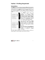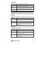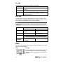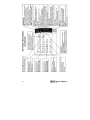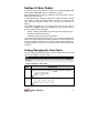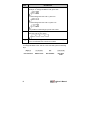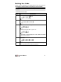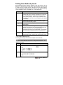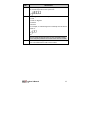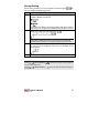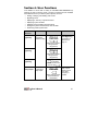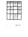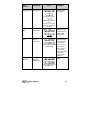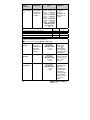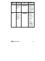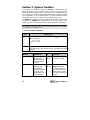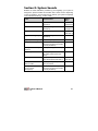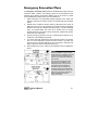
1
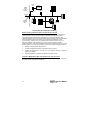
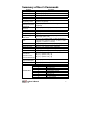
User’s Manual Important Notice This manual is delivered subject to the following conditions and restrictions: ✦ This manual contains proprietary information belonging to Rokonet Electronics Ltd. Such information is supplied solely for the purpose of assisting explicitly and properly authorized users of the system. ✦ No part of its contents may be used for any other purpose, disclosed to any person or firm or reproduced by any means, electronic or mechanical, without the express prior written permission of Rokonet Electronics Ltd. ✦ The text and graphics are for the purpose of illustration and reference only. The specifications on which they are based are subject to change without notice. ✦ Information in this document is subject to change without notice. Corporate and individual names and data used in examples herein are fictitious unless otherwise noted. Copyright 2003 Rokonet Electronics Ltd. All rights reserved. ii User's Manual Customer Information RTTE Compliance Statement Hereby, Rokonet Electronics Ltd, declares that ORBIT-14 (RP214MC0000A) with wired accessories (including cables) is in compliance with the essential requirements and other relevant provisions of Directive 1999/5/EC. Telephone Connection (Ref.: FCC Part 68) 1. This equipment, Alarm Control Panel, brand named ORBIT-14 (RP214MA0000A), complies with Part 68 of the FCC Rules and the requirements adopted by the ACTA. On the bottom panel of this equipment is a label, that contains among other information, a product identifier in the format US:RKEAL10BRP214MA. If requested, this number must be provided to the telephone company. 2. This equipment is designed to be connected to the telephone network using a terminal block, which is Part 68 compliant and properly installed RJ31X connector. See Installation Instructions for details. 3. The REN is used to determine the number of devices that may be connected to a telephone line. Excessive RENs on a telephone line may result in the devices not ringing in response to an incoming call. In most but not all areas, the sum of RENs should not exceed five (5.0). To be certain of the number of devices that may be connected to a line, as determined by the total RENs, contact the local telephone company. The REN of alarm system is part of the product identifier that has the format US:RKEAL10BRP214MA. 4. If the Alarm Control Panel causes harm to the telephone network, the telephone company will notify you in advance that temporary discontinuance of service may be required. If advance notice is not practical, you will be notified as soon as possible. Also, you will be advised of your right to file a compliant with the FCC if it is necessary. 5. The telephone company may make changes in its facilities, equipment, operations or procedures that could affect the operation of the equipment. If this happens the telephone company will provide advance notice in order for you to make necessary modifications to maintain uninterrupted service. 6. If trouble is experienced with the Alarm Control Panel for repair or warranty information please contact: Rokonet Industries USA Inc 2822 NW 79th Ave. Miami, Florida 33122 USA, phone number 305 592 3820, URL: [email protected]. If the equipment is causing harm to the telephone network, the telephone company may request to disconnect the equipment until the problem is resolved. 7. The control panel is described in the Installation Manual. Connection to telephone company provided coin service is prohibited. Connection to party lines service is subject to state tariffs. 8. Alarm Control Panel must be able to seize the telephone line and place a call in an emergency situation. It must be able to do this even if other equipment (telephone, answering system, computer modem, etc.) already has the telephone line in use. To do so the alarm control panel must be connected to a properly installed RJ31X jack that is electrically in series with and ahead of all other equipment attached to the same telephone line. Proper installation is depicted in the figure below. If you have any questions concerning these instructions, you should consult your telephone company or a qualified installer about installing the RJ31X jack and Alarm Control Panel for you. User's Manual iii RJ-31X Jack Network Service Provider's Facilities Alarm Dialing Equipment Unused RJ-11 Jack Computer Telephone Line Telephone Network Demarcation Point Fax Machine Telephone Unused RJ-11 Jack Answering System Telephone Customer Premises Equipment and Wiring Radio Frequency Interference (Ref.: FCC Part 15, Para. 15.105) This equipment has been tested and found to comply with the limits for a Class B digital device pursuant to Part 15 of the FCC Rules. These limits are designed to provide reasonable protection against harmful interference in a residential installation. This equipment generates, uses, and can radiate radio frequency energy and, if not installed and used in accordance with the instructions, may cause harmful interference to radio communications. However, there is no guarantee that interference will not occur in a particular installation. If this equipment does cause harmful interference to radio or television reception, which can be determined by turning the equipment off and on, the user is encouraged to try to correct the interference by one or more of the following measures: 1. Reorient or relocate the receiving antenna. 2. Increase the separation between the equipment and the receiver. 3. Connect the equipment into an outlet on a circuit different from that to which the receiver is connected. 4. Consult the dealer or an experienced Radio/TV technician for help. Changes or Modifications (Ref.: FCC Part 15, Para. 15.21 and 15.27) Changes or modifications to this unit not expressly approved by Rokonet, Ltd., could void the user's authority to operate the equipment. iv User's Manual Summary of User’s Commands Function System Arming Group Arming System Disarming Duress Disarming Silencing an Alarm Bypassing / Unbypassing a Zone Quick Bypassing Zone Reset Smoke Detector(s) Utility Output Operation Display Troubles Display Memory Setting/Changing a User Code Procedure [User Code] + [Arm] [User Code] + [Stay] + [Group Number:: 1/2/3 / 0=All Groups] [User Code] [Duress Code] [User Code] [ ✱ ] + [ 1 ] + [User Code ] + [ 2 digit zone number to be bypassed / unbypassed] [ ✱ ] + [ 1 ] + [ 2 digit zone number to be bypassed / unbypassed] [ ✱ ] + [ 2 ] + [User Code ] + [Smoke Output No.] [ ✱ ] + [ 2 ] + [User Code ] + [Utility Output No.] [✱]+[3] [✱]+[4] [ ✱ ] + [ 5 ] + [1] + [Master Code] + [2 Digit User No. to be set/changed] + [New Code] [ ✱ ] + [ 5 ] + [2] + [Master Code] + [2-digit User Number to be set/changed] + [Authority Level No.: 0 = User, 1 = User Un-Bypass, 2 = Cleaner, 3 = Service) Set Date [ ✱ ] + [ 6 ] + [ 1 ] + [Master Code] + [MM] [DD] [YY] Set Time [ ✱ ] + [ 6 ] + [ 2 ] + [Master Code] + [HH] [MM] Set Auto Arm Time [ ✱ ] + [ 6 ] + [ 3 ] + [Master Code] + [HH] [MM] Set Follow-Me Phone [ ✱ ] + [ 7 ] + [ 1 / 2 / 3 / 4 ] + [Master Code] + Phone No. + [ #] Erase Follow-Me Phone [ ✱ ] + [ 7 ] + [ 1 / 2 / 3 / 4 ] + [Master Code] + [#] Maintenance: [ ✱ ] + [ 8 ] + [Master Code] + [1] On/Off Buzzer [ ✱ ] + [ 8 ] + [Master Code] + [2] On/Off Door Chime [ ✱ ] + [ 8 ] + [Master Code] + [3] On/Off Audible Kiss-Off Get Event From Event [ ✱ ] + [ 9 ] + [Master Code] Logger (LCD Keypad) Test System [ ✱ ] + [ 0 ] + [Master Code] Setting User Authority Level Trouble Table LED 1 2 3 4 5 6 7 8 User's Manual Trouble Low Battery AC Power Loss Clock Not Set Communication Trouble Bell Loop Trouble Phone line cut Bell/ Box/ Keypad Tamper Day Zone Trouble v vi User's Manual Table of Contents Section 1: Getting Acquainted 1 Introduction 1 Terms and Definitions 2 Section 2: Your Keypad 4 Visual Indicators 4 Power LED Arm LED Ready LED Fire LED Zone LED KEYS 5 5 5 6 6 6 Emergency Keys 7 Section 3: User Codes 9 Setting/Changing the User Codes 9 Deleting User Codes 11 Setting User Authority Levels 12 Section 4: Arming and Disarming the System 14 Arming 14 Away Arming Group Arming Determining Which Group is Armed Quick Arming Keyswitch Arming Disarming Disarming the System Silencing an Alarm Duress Disarming User's Manual 14 15 16 16 17 17 17 17 18 vii Section 5: Zone Bypassing 19 Code Bypassing 19 Quick Bypass 19 Determining Which Zone Is Bypassed 20 Section 6: User Functions 21 Section 7: System Troubles 26 Section 8: System Sounds 29 viii User's Manual Section 1: Getting Acquainted Introduction Congratulations on your purchase of Rokonet’s ORBIT-14 Security System. The ORBIT-14 has been specifically designed to meet a wide range of security needs for many residential and small commercial applications. You communicate with your ORBIT-14 through its keypad(s). Using its keys, you can issue commands to your system. In turn, the system can communicate information to you via its indicators and by the sounds it makes. Your ORBIT-14 security system also consists of a variety of sensors, detectors, and contacts placed throughout the premises and designed to recognize abnormal conditions. Typically, your system protects against intrusion. Some systems may also have fire protection or environmental protection (such as gas or water level sensors). All of your system's detectors, sensors, and contacts are wired to the control panel. As such, your system always knows the status of any protected door, window, hallway, room, or area. Similarly, it knows if a smoke detector has been activated. The control panel, which contains the system's electronics and backup battery, functions in the background and, for purposes of security, is installed out of sight. This User's Manual contains all the information needed to operate your Rokonet ORBIT-14 Security System and to get the most from it. User's Manual 1 Terms and Definitions Becoming familiar with the following terms and definitions will help you to better understand and use your system. Authority Level: Each individual using the system is assigned a user code, which, in turn, is linked to an Authority Level. Users with a "higher" authority level have access to a greater number of system functions, while those with a "lower" authority level are more restricted in what they may do. There are five different Authority Levels available for users of the ORBIT-14, as described on page 12. Away Arming: This type of arming is most often used when the premises are empty. All of the system's intrusion detectors are ready to sound an alarm, if violated. Bypass: It may be convenient to have one (or more) of the zones in your installation bypassed and thus ignored by your system. You can bypass a zone by using a user code or alternatively you can perform Quick Bypassing without a user code. Quick Bypassing is determined during the installation mode. Central Station: Besides producing audible alarms at your premises, it's likely that your system is set up to report alarms to a Central Station – a facility which continually monitors the activities of security systems, usually via the telephone network, and dispatches the proper authorities as required. Chime: The chime is a short keypad tone, which can be set to annunciate the violation of selected intrusion zone(s) during the disarmed period. For example, the chime tone can be used to annunciate the arrival of a customer each time the front door opens. The chime can be enabled or disabled at your discretion. Day Zone: A Day Zone is one in which a violation during the disarmed period results only in a trouble indication (see page 26). However, the same violation during the armed period will cause a full-fledged alarm. Duress Disarming: If you are ever coerced into disarming your system, you can comply with the intruder's wishes while sending a silent, duress alarm, to the Central Station. To do so, you must use a special Duress Code, which will disarm the system in the regular manner, while simultaneously transmitting a silent alarm to the central station (see page 18). Event Log: A list of system events can be displayed on an LCD keypad or uploaded to the alarm company via the Upload/Download software and printed for further analysis. Exit/Entry Delay: Your security system must incorporate an entry/exit delay to allow proper entry and exit to and from the premises without causing inadvertent alarms. A delay period was defined during your system's installation to provide suitable time for your entry and exit. 2 User's Manual Follow-Me Phone: In addition to the standard event reporting to the Central Station, the system can send alarm messages or tones to a designated system user's telephone. The Follow-Me function can support four phone numbers. Group: A number of zones can be gathered as one unit to allow partial arming. Each zone can be assigned to any one (or a combination) of three groups. Keyswitch: Your system may also be equipped with a keyswitch, which is useful for simple arming and disarming operations (usually at a remote location). Panic Button: A special panic button can be installed at any preferred location to allow immediate and flexible alarm notification in time of distress. Quick Arming: Arming without using a user code. For Away arming, simply press the key. For Group Arming, use the key with the group number. Quick Arming is determined during the installation mode. For more information, see page 14. Upload/Download: Software used by the installer for programming the Orbit 14 and by the user for operating the system and viewing system status. Trouble Reporting: If required, your security system may also report to the Central Station any troubles or malfunctions it senses, so that a service call can be made. User Code: A four-digit code that is used to perform many of the ORBIT-14 functions. Utility Output (UO): A household appliance. In addition to your system's normal operation, it is possible to place a household appliance or premises lighting under the control of the ORBIT-14 where it can be conveniently turned on and off automatically, or by user command from any system keypad. Voice Announcement Message: An optional Voice Module can be added to your system. Up to three short messages can be recorded. These messages replace the alarm tones normally produced in the Follow-me mode. Zone: A single detector, or collection of detectors, usually relating to a certain area of the premises or type of protection. Zones that use devices designed to detect break-ins are called intrusion zones. Another kind of zone may contain one or more smoke detectors. Such zones are called fire zones. Since a specific number distinguishes each zone, the ORBIT-14 can report the zone status and register all the zone’s events reported by the zone detector. User's Manual 3 Section 2: Your Keypad The ORBIT-14 can support up to 5 keypads, with a choice of four styles: LCD, 6 LEDs, 8 LEDs or 14 LEDs. This manual discusses the operation of the ORBIT-14 from the LED keypads. This section discusses the keypad’s visual indicators and the use of its keys. For operation from the LCD keypad refer to the LCD instruction manual. Visual Indicators Each keypad in your system reports its status via its LED (lighted) indicators. Through its keys, you can enter commands to "arm" and "disarm" the system, bypass intrusion zones, report emergencies, silence an alarm in progress, as well as other useful functions. The four LED indicators found at the upper right provide typical system indications, which are discussed herein. Some indicators have additional functions, which are discussed later on. 4 User's Manual Power LED The Power LED indicates the status of system operation. CONDITION DESCRIPTION ON The system is operating properly from commercial (AC) power; its backup battery is in good condition. OFF The system is inoperative due to lack of power (from both commercial AC and backup battery); servicing is required. FLASHING (Disarm State) Indicates a trouble condition; for more information on displaying and attending to trouble conditions, see page 26. NOTE: If a trouble condition exists, the Power LED will flash only when the system is in its disarmed state. Once the system is armed, a previously flashing Power LED will light steadily. Arm LED The Arm LED indicates whether or not the system's intrusion detectors are armed. CONDITION EXPLANATION ON The system's intrusion detectors are armed; subsequent violations of a protected point or area (e.g., a door, a window, unauthorized motion) will result in a burglar alarm. OFF The intrusion function of the system is disarmed. FLASHING Occurs when using the emergency keys on the keypad to send panic, fire or special emergency alarms, or when viewing alarms after disarming or when a tamper alarm has occurred in the system. Ready LED The Ready LED indicates whether or not the system's intrusion zones are secured and ready to be armed. CONDITION EXPLANATION ON All intrusion zones are secure; the system is ready to be armed. OFF One or more intrusion zones are not secure and the system is not ready to be armed. Before the system can be armed, the condition must be addressed. FLASHING Indicates that one or more of the system's intrusion zones have been bypassed. For more information, see Zone Bypassing, page 19). User's Manual 5 Fire LED The Fire LED is an indicator of a fire alarm in the system. CONDITION EXPLANATION ON A fire alarm or fire emergency is in progress or has recently occurred. OFF All fire zones are operating normally. FLASHING A fault has been detected in the system's fire zone and needs to be corrected; for more information on fire zone trouble (see page 28). Zone LED The Zone LEDs indicate the status of each of the system’s intrusion zones. When entering the Trouble indication function ([À][3]) the LEDs of zones 1-8 represent a trouble indication as described on page 26. NOTE: In the 6–Zone LED keypad, LEDs 7 and 8 will be labeled Tamper and Day respectively. CONDITION EXPLANATION System Disarmed System Armed OFF The corresponding zone is secured. The corresponding zone is secured. ON N/A An alarm has occurred in the indicated zone. NOTE: FLASHING A Zone LED on together with a flashing ARM LED indicates a zone tamper alarm in the system. The indicated zone is N/A not secured. KEYS The keys on the keypad can be used for a variety of functions. The role of each key is explained below: Keys Function These keys are used to input the numeric codes that may be required for arming, disarming, triggering emergency alarms, along with several other special functions. 6 User's Manual Keys Function The [À] key is used to enter the User Functions mode (see page 21). Used to arm the system's intrusion detectors to the "AWAY" mode; it may be necessary to enter a numeric User Code before pressing the Arm key. Refer to page 14 for additional information. Used to arm the system's intrusion detectors to the "Group" mode; it may be necessary to enter a numeric User Code before pressing the page 15 for additional information. key. Refer to Emergency Keys Your keypad provides three predefined key sets that can be pushed at any time the police, fire department, or special emergency is required. Panic Key and simultaneously for at Pressing least two seconds will activate a Panic Key alarm. Fire Emergency and simultaneously for at Pressing least two seconds will activate a Fire Emergency alarm. Special Emergency and simultaneously for at Pressing least two seconds will activate a Special Emergency alarm. The annunciation that results during these emergency alarms, along with other system sounds, is described in Section 8: System Sounds, page 29. For a summary of the keypad’s features refer to the figure on the next page. User's Manual 7 8 User's Manual Section 3: User Codes To perform many of the ORBIT-14's functions, a four-digit security code (often called a User Code) must be entered at the keypad. Each individual using the system is assigned a user code, which, in turn, is linked to an Authority Level. In residential systems, it's likely that all family members will share the same User Code. In certain commercial systems, however, it's common to give each authorized employee his/her own User Code (as discussed on page 9). Your ORBIT-14 permits up to 20 User Codes. One of the codes is considered the Master Code; the individual(s) using the Master Code is given the following special privileges: • Adding, modifying, and deleting User Codes and User Authority Levels • Setting the system's internal clock • Performing certain system functions and tests Your ORBIT-14 was given a Master Code of 1–2–3–4 during manufacturing. Unless your alarm company has already changed it to suit your preference, it's best to modify this code to one, which is unique and personalized. To change the Master Code and/or to set up User Codes, follow the procedure on page 9. Setting/Changing the User Codes The user assigned the Master Authority Level can change all user codes but cannot view the digits in the user codes. NOTE: The system must be disarmed in order to set or change user codes. The ARM LED will be OFF. To set/change a user code: STEP DESCRIPTION 1 Enter the User Functions Mode ( 2 Enter the current 4-digit Master Code: User's Manual ) and select Codes (5): 9 STEP 3 DESCRIPTION Enter a 2-digit user code. Example: To change the Master Code, press "00": To enter/change the User Code 1, press "01": To enter/change the User Code 12, press "12": It is possible to enter/change up to 20 User Codes. 4 Enter the new 4-digit code selected for the Master Code or for the User Code of your choice: 5 If successful, the keypad will emit a one-second confirming tone. The selected User Code is now in effect. Example: To change the Master Code 1234 to a new code 7890, press the following keys: [✱][5] [1] [1] [2] [3] [4] [00] [7] [8] [9] [0] User Function Master Code User Number New User Code 10 User's Manual Deleting User Codes At times, it may be desirable to completely delete a User Code. Note that it is impossible to delete the Master Code (although it can be changed). NOTE: The system must be disarmed in order to set or change user codes. The ARM LED will be OFF. To delete a user code: STEP DESCRIPTION 1 User Functions Mode ( 2 Enter the current 4-digit Master Code: 3 To delete the User Code 1, press "01": ) and choose Codes [5] [1]: To delete the User Code 12, press "12": It is possible to enter/change up to 19 User Codes. The master code cannot be deleted. 4 Enter 0-0-0-0 (which is NOT a valid code) to clear the selected User Code. 5 If successful, the keypad will emit a one-second confirming tone. The selected User Code is now deleted. User's Manual 11 Setting User Authority Levels Each individual using the system is assigned a user code, which, in turn, is linked to an Authority Level. Those with a "higher authority" have access to a greater number of system functions, while those with a "lower authority" are more restricted in what they may do. There are five different Authority Levels available for users of the ORBIT-14, as described below: LEVEL DESCRIPTION Master Enables all operations for the system as: Arm/Disarm, Activate utility outputs, change and delete user codes, set time, date, auto arming, Follow-Me numbers and view system events memory. There is only one Master code in the system. This code can only be changed by the installer or the Master. User Enables basic operations, such as Arm/Disarm, Bypass zones and activate utility outputs. Unbypass Same as the User authority level without the ability to bypass zones. Cleaner Used only for one-time arming and disarming (cannot bypass), after which the code is automatically erased and should be redefined. This code is typically used residentially for cleaners, home attendants, and repairmen who must enter the premises before the owner(s) arrive. Service A service user cannot disarm a system armed by another user with a different authority level or a system armed in Quick Arming mode. A service user cannot bypass a zone. To set the authority level: To change the authority level follow the example in the next table. NOTE: The system must be disarmed in order to set or change user authority level. The ARM LED will be OFF. STEP 12 DESCRIPTION 1 Enter the User Functions Mode ( [5][2]: 2 Enter the current 4-digit Master Code: ) and select Codes User's Manual STEP 3 DESCRIPTION Enter the 2-digit user number. For example: To set authority level for user 1 press "01". 4 Enter 1digit for the user authority level as follows: 0: User 1: User Un - Bypass 2: Cleaner 3: Service For example, to enter/change User’s authority level to Service, press "3": NOTE: You can change the authority level for 19 users. The Master authority level is assigned by default to user number 00 and cannot be modified. 5 If successful, the keypad will emit a one-second confirming tone. The selected User Code is now in effect. User's Manual 13 Section 4: Arming and Disarming the System Arming Arming your system enables its intrusion detectors to trigger an alarm when violated. Remember, fire protection and the protection offered by the keypad's emergency keys are always armed and always available. If your system is equipped with environmental protection (for example, gas and/or water level detection) it is always available too. NOTE: Before you arm your system, all of its zones must either be secured or bypassed. The keypad's READY LED, if lit, indicates that all zones are secured. If the READY LED is not lit, a numbered LED corresponding to the unsecured zone(s) will be flashing. Before you can arm your system, the indicated zone(s) must be identified and secured. If this is not possible, the affected zone(s) can be bypassed and will be ignored by the system during the subsequent armed period. Recall that bypassing, however necessary, reduces the system's degree of intrusion protection. Away Arming Away arming prepares all of the system's intrusion detectors to trigger an alarm, if violated, and is used when leaving the premises empty. STEP 1 DESCRIPTION Check the READY LED on your keypad. If lit or flashing, the system is READY to be armed. If NOT lit or flashing, the system is NOT ready to be armed. In this case secure or bypass the violated zone(s) and then proceed. 2 Enter your 4-digit User Code and press . NOTE: If you make a mistake when entering your User Code, the keypad will produce three short beeps. If so, re-enter the code correctly. 3 14 Leave the premises and close the door. The keypad will beep as it counts down the Exit Delay period. User's Manual Group Arming Group arming enables you to arm a number of zones using the Ask your installer about defining groups. STEP 1 key. DESCRIPTION Check the READY LED on your keypad. If it is lit or flashing, the system is READY to be armed. If it is NOT lit or flashing, the system is NOT ready to be armed. In this case secure or bypass the violated zone(s) and then proceed. 2 Enter your 4-digit User Code followed by . NOTE: If you make a mistake when entering your User Code, the keypad will produce three short beeps. If so, re-enter the above sequence correctly. 3 Enter the group number. You have 4 options for group arming: 1, 2, 3 and 0. To arm all groups, use the “0”. For example, to arm group 3 press: 4 The keypad will beep as it counts down the Exit Delay period. NOTES: Pressing + [Group Number] + cancel the Entry Delay time. Pressing the keypad. + [Group Number] + User's Manual # will silence the beeps on the keypad and during exit time will silence the beeps on 15 Determining Which Group is Armed The system must be armed. To identify the armed group(s) STEP 1 DESCRIPTION Enter your 4-digit User Code followed by . NOTE: If your system is defined with Quick Arming simply press the key. The keypad’s first 3 Zone LED(s) corresponding to the armed group(s) will light for several seconds. Zone LED 1 represents Group 1. Zone LED 2 represents Group 2. Zone LED 3 represents Group 3. 2 NOTE: If the system is armed in Away mode the Zone LEDs on the keypad will not light. Quick Arming Quick arming enables you to quickly arm the system. NOTE: Your installer should define Quick Arming. To quick arm using away arming: ✦ Press . The system is fully armed. To quick arm a group: ✦ Press armed. followed by the group number. The selected group(s) is NOTES: If the system is defined with Quick Arming, you can arm more than one group at the same time. In effect arming one group on top of the other. For example: If Group 1 is armed and you want to arm Group 2 simply press + [2] and Group 2 will be armed. If the system is not defined with Quick Arming, then you cannot arm one group on top of the other. In this case you can either arm only one group ( + 1,2 or 3) or all groups by using the option + [0]. For example: If Group 1 is armed and you want to arm Group 2, then first you need to disarm Group 1 and only then arm Group 2 using the sequence: + [2]. 16 User's Manual Keyswitch Arming If your system is equipped with a special keyswitch, it can, with the twist of a key, be toggled through Arm (Away) and Disarm modes. Disarming Disarming the System Disarming your system deactivates its detectors. Remember, fire protection and the protection offered by the keypad's emergency keys are always armed and always available. STEP DESCRIPTION 1 If outside the premises, open an "entry" door; the keypad(s) will beep indicating that the Entry Delay period has begun. 2 Disarming an armed system: Before the Entry Delay expires, enter your 4-digit User Code. NOTE: If you make a mistake when entering your User Code, the keypad will produce three short beeps. If so, re-enter the above sequence correctly. Silencing an Alarm STEP DESCRIPTION 1 If outside the premises, open an "entry" door; the keypad(s) will beep indicating that the Entry Delay period has begun. 2 Observe the keypad. If any of the following conditions is evident, an alarm has occurred: • The ARM LED is flashing • A Zone LED is lit steadily • The FIRE LED is lit steadily 3 Disarm the system by entering your User Code: NOTE: It is best to enter the premises only after police or a security company has investigated and you are confident that the burglar is no longer on your premises. User's Manual 17 IMPORTANT: If the alarm was caused by a tripped Smoke Detector(s), the keypad's FIRE LED will remain lit, providing an indication that the fire system must be reset before it will be capable of detecting subsequent alarms. Furthermore, until reset, you will be prevented from arming your system. To reset the fire system and to turn off the FIRE LED, see Reset a Smoke Detector, in the table on page 22. Duress Disarming If you are ever coerced into disarming your system, you can comply with the intruder's wishes while sending a silent duress alarm to the Central Station. To do so, you must use a special duress code that will disarm the system in the regular manner, while simultaneously transmitting the duress alarm. All user codes can activate the Duress disarming. To use a duress code, add 1 to the last digit of your user code, as shown in the table below: User Code Duress Code 1-2-3-4 1-2-3-5 5-6-7-8 5-6-7-9 6-7-8-9 6-7-8-0 NOTE: Under no circumstances must the duress code be used haphazardly or without reason. Central Stations, along with Police Departments, treat duress codes very seriously and take immediate action. To disarm using a duress code: STEP DESCRIPTION 1 If outside the premises, open an "entry" door. The keypad(s) will beep indicating that the Entry Delay period has begun. 2 Enter your 4-digit Duress Code: Once entered, it will disarm your system and send a silent alarm to the Central Station. NOTE: A utility output in your system may be programmed to be activated continuously after an entry of the duress code. If so, deactivation must be performed manually by one of the following procedures: 1. Arming the system. 2. Disarming the system after an alarm occurred while the utility output was still activated. 18 User's Manual Section 5: Zone Bypassing When an intrusion zone is not secured, the READY LED on your keypad will not light, nor can the system be readily armed. Noting which LED(S) are flashing in the keypad’s ZONES area can identify the faulted intrusion zone. Bypassing a zone enables you to arm the system even if a zone is open/not secured. WARNING: A bypassed zone may reduce the system's security capability. Code Bypassing To bypass such a zone(s) and cause it to be ignored by the system, enter the following sequence correctly: 2-DIGIT ZONE TO BE BYPASSED NOTES: If you make a mistake when entering your User Code, the keypad will produce three short beeps. Re-enter if necessary. Enter a two-digit code for the zone number. For example, for zone five enter 05. An additional zone(s) can be bypassed at the same time by adding its number to the sequence. For example, to bypass Zones 2 and 3, press: [ ] + [ 1 ] + [USER CODE] + [ 02 ] + [ 03 ]. The same sequence can “toggle” the bypass(es) during the disarmed period so that they may be either applied or removed. Press [#] or [✱] to approve or wait two seconds (timeout period). Quick Bypass If the system is programmed for Quick Bypass, you can follow the same procedure as described above without entering the 4-digit User code or you can use the following option for extra quick bypassing: To execute extra quick bypass: Press the first digit of the zone number for at least 2 seconds, until a beep is heard. After the beep enter the second digit of the zone number. For example, to bypass zone 05: [ 0 ] for 2 seconds + [ 5 ] User's Manual 19 An additional zone(s) can be bypassed at the same time by adding its number to the sequence. For example, to bypass Zones 05, 07 and 12, press: [ 0 ] for 2 seconds + [ 5 ], [0] [7] [1] [2]. NOTES: Only the first digit of the first zone should be pressed for 2 seconds. The same sequence can “toggle” the bypass(es) during the disarmed period so that they may be either applied or removed. Determining Which Zone Is Bypassed The system must be disarmed. If the keypad’s READY LED is flashing, there is at least one bypassed zone, in the system. To identify the bypassed zone: STEP DESCRIPTION 1 If quick bypass is enabled in your system, simply press: 2 Observe the keypad’s ZONES area. LED(s) corresponding to the bypassed zone(s) will light for several seconds. NOTES: The READY LED, when flashing, indicates that there is one or more bypassed zones. Any zone(s) bypassed during the disarmed period will remain bypassed when the system is armed. Zone(s) that are bypassed while the system is armed will automatically be restored to the normal unbypassed condition when the system is disarmed. 0 20 User's Manual Section 6: User Functions Your ORBIT-14 comes with a variety of selectable User Functions. By entering the User Functions mode, a number of options become available which determine how your alarm system operates, such as: • Adding, modifying, and deleting User Codes • Bypassing zones • Displaying a "memory" of previous alarms • Displaying system troubles • Disabling (and re-enabling) keypad sounds • Setting the system's internal clock, time and date • Performing certain system tests USER DESCRIPTION PRESS COMMENTS FUNCTION Zone Bypassing Bypasses or unbypasses selected zone(s) + + USER CODE + Refer to Zone Bypassing procedures, as discussed on page 19. (2-digit zone number to be bypassed or unbypassed) Quick Bypassing + + (2-digit zone number to be bypassed or unbypassed) Extra Quick Bypassing Activate a Utility Output The first digit of the zone for at least 2 seconds and then the second digit . Activates or de-activates a Utility Output + + USER CODE + (Utility Output number to be activated or deactivated) User's Manual Maximum of six utility outputs. Please consult your Alarm Company or Installer. 21 USER FUNCTION DESCRIPTION Reset a Smoke Detector Resets a Smoke Detector PRESS + + USER CODE + (Utility Output number responsible for resetting the Smoke Detector(s)) COMMENTS Refer to System Troubles on page 26, and consult your Alarm Company or Installer. Displays system problem(s) causing the POWER LED to flash + Refer to System Troubles on page 26, and consult your Alarm Company or Installer. Display Alarm Reviews any alarms occurring Memory + Via its LEDs, the keypad reveals the zone(s) in which the alarm occurred during the previous armed period. After several seconds the LEDs will restore to normal. Display System Troubles during the last armed period Set User Code Adds, modifies + or deletes User and Master Code(s) + + MASTER CODE + Refer to Setting/Changing User Codes on page 9. (2 digit user code) + (New user code) Note: Use 0-0-0-0 to delete the Code. 22 User's Manual USER FUNCTION DESCRIPTION Set User Sets the user Authority Level authority level PRESS + + + MASTER CODE COMMENTS For more on authority levels, see page 12. + (2 digit user code) + (New authority level code; 0= User; 1= User Unbypass; 2= Cleaner; 3= Service) Setting the Date Sets the system's date + + MASTER CODE + + Setting the Time Sets the system’s internal clock + + MASTER CODE + Enter the date in MMDDYY format. For example, for May 28, 2003, enter 052803. Examples of 24hour time format: • For 12:30 AM, enter 0030. Enter the time in 24-hour • For 8:45 AM, enter 0845. HH:MM format. • For 6:15 PM, enter 1815. The clock must be set to insure proper system operation. Setting the Auto Arm Sets auto arming for a specified time + + MASTER CODE Use 24-hour time format. + Enter the time in 24-hour HH:MM format. User's Manual 23 USER FUNCTION DESCRIPTION Set Follow-Me Sets the first Phone Number phone number 1- 4 for the Followme function (up to 32 digits) PRESS COMMENTS + You can include the special functions described in the table below, as required. or + or + or + + MASTER CODE + Phone Number + [#] Function Stop dialling and wait for a new dial tone Wait a fixed period before continuing Switch from Pulse to Tone (or from Tone to Pulse) Send the DTMF ✱ character Sequence Results [STAY], [1] A [STAY], [2] B [STAY], [3] C [STAY], [✱] [STAY], [#] Send the DTMF # character ✱ # To Erase a phone number use the sequence: [ ✱ ] + [ 7 ] + [ 1 / 2 / 3 / 4 ] + [Master Code] + [#] Keypad Sounder Chime Operation Determines how the keypad's internal sounder will operate under specific conditions + + MASTER CODE + + + MASTER CODE + Audible KissOff Indication + + MASTER CODE + 24 After entering the Master Code, to press enable/disable current operation of keypad's beeps (see page 29). Disable/enable the chime for intrusion zones having this feature (see page 2.) Disable/enable the Audible Kiss-Off which is an indication when the dialler, after successfully transmitting data to the monitoring station receives the “Kissoff” signal. User's Manual USER FUNCTION DESCRIPTION PRESS Event Logger Retrieves events located in the event logger memory (up to 250 events). + System Testing Provides a brief test of the following: • Keypad LEDs • Keypad sounder • External siren • Standby battery + MASTER CODE + + MASTER CODE COMMENTS Use this option only with the LCD keypad. A list of events are presented from the last entered to the first registered. For more information, refer to the LCD instructions. The external sounder will be activated momentarily. • The keypad's LEDs will flash. • If enabled, the keypad's sounder will beep. • A low battery or a loss of commercial power will cause the POWER LED to flash; if so, consult your security dealer. User's Manual 25 Section 7: System Troubles Your ORBIT-14 is designed to report any troubles or malfunctions it may detect. Notification that a problem exists is made to the user through indications on the keypad(s) and, in many cases, to the Central Station and to your dealer. Any incidence of trouble should be taken seriously and acted upon immediately. If not remedied quickly, a trouble condition will likely compromise your system and prevent it from properly doing its job. The ORBIT-14 is designed to be as trouble-free as possible. In the event of a problem, the POWER LED will flash about once every second. If this happens, perform the sequence described below to determine the problem. NOTES: It is possible for more than one trouble to be present at the same time. If so, multiple Zone LEDs will be lit simultaneously. To view trouble conditions: STEP DESCRIPTION 1 Enter the User Functions Mode by pressing View Troubles (3): 2 The keypad will beep and its LEDs will light, reflecting the information below. After several seconds, the display will return to normal. TROUBLE DESCRIPTION LED Low Battery The capacity of the Zone 1 battery is low or LED On missing and needs to be recharged or replaced. AC Power Loss The commercial Zone 2 power has been LED On interrupted; the system will continue to operate on its standby battery as long as possible. 26 and then select RESPONSE Contact your Alarm Company or Installer. Check that the ORBIT-14's Plug-In Transformer has not been removed from its outlet. If intact, contact your Alarm Company or Installer. User's Manual TROUBLE DESCRIPTION LED Clock Not Set The system's clock Zone 3 has lost track of the LED On time and/or date. RESPONSE Set the system's time and date, see page 23. Communication The ORBIT-14 has Zone 4 Trouble failed in its attempts LED On to report an alarm or trouble condition to the Central Station. Check that your telephone line is functioning If not, contact your local telephone company. Bell Loop Trouble The ORBIT-14 has Zone 5 failed in its attempt LED On to identify the Bell Loop. Check to see if your external bell has been tampered with. If the problem exists contact your Alarm Company or Installer. Phone line cut The telephone line Zone 6 used for Central LED On Station communication is either disconnected or inoperative. If all premises telephones are operating properly, contact your Alarm Company or Installer. Bell/ Box/ Indicates a tamper Keypad Tamper condition in the external sounder or in the Panel Box or in any keypad. Zone 7 LED On Day Zone Zone 8 LED On A zone designated as a DAY zone has been faulted during the disarm period. User's Manual If not, contact your local telephone company. Contact your Alarm Company or Installer. (Tamper in 6-LED keypad) Check the integrity of the indicated zone. (Day in 6-LED keypad) 27 To disable the Fire Alarm: In certain cases, the keypad's FIRE LED may remain lit steadily, even though there is no alarm in progress and the system is disarmed. USER FUNCTION The FIRE LED remains lit. DESCRIPTION AND REMEDY After a fire alarm has occurred and been silenced, the keypad's red FIRE LED will remain lit steadily if a Smoke Detector (presumably the one which caused the alarm) remains tripped. Until reset, a tripped Smoke Detector will prevent the READY LED from being lit, and will NOT permit the system to be armed. To reset a tripped Smoke detector and to extinguish the red FIRE LED, perform the following procedure: + + USER CODE + (Utility Output number which is responsible for resetting the Smoke Detector) Consult your Alarm company or Installer for alternate information on resetting smoke detectors, if applicable. Once done, the Ready LED will indicate the system's status and you will be able to arm your system. NOTE: You may need to perform this procedure several times in order to prevent the smoke detector(s) from re-detecting any remaining smoke. 28 User's Manual Section 8: System Sounds Besides the visual indications provided by your keypad(s), your system is designed to produce audible annunciation after certain events. Depending on the circumstance, such sounds may be made by your system's keypad(s) or its external sounder (e.g., a siren or bell). EVENT KEYPAD SOUND SIREN/ BELL Intrusion Alarm Optional (see Note 5) Yes (continuous) Fire Alarm Rapidly repeating tones (see Note 3) Yes (staggered) Keypad Police Emergency A momentary chirp Optional (see Note 2) Keypad Fire Emergency Rapidly repeating tones (see Note 3) Yes Keypad Special Emergency A momentary chirp No Arming or disarming A one second tone if completed correctly; three rapid error beeps if incorrect (see Note 3) No Entering an incorrect key sequence Three rapid beeps (see Note 3) No Entry Delay countdown Slowly repeating tones until the entry delay period expires (see Note 3) No Exit Delay countdown Slowly repeating tones until the exit Optional delay period expires (see Note 3) (see Note 1) Bell Loop Trouble or Low Battery Trouble Rapidly repeating 2 beeps until the [#] key is pressed. No Entering data in the User Functions mode (see page 21) A one second tone if completed correctly; three rapid error beeps if incorrect (see Note 3) None User's Manual 29 NOTES: 1. If selected during the installation, a brief "chirp" may be heard from the siren when the Exit Delay period expires. See page 2 for additional information. 2. Whether or not the Police Emergency alarm is enunciated by the external sounder is determined by the alarm company during your system's installation. 3. Keypad beeps in response to Entry/Exit Delay countdowns, Keypad Fire Emergencies, and keypad errors and confirmations are typically enabled. At the user's discretion, such beeps may be disabled. See page 2 for additional information. 4. Any intrusion zone, if selected for the chime feature, will cause the keypad to annunciate an event when violated during the disarmed period. Through User Functions the chime can also be disabled when not desired. See page 2 for additional information. 5. Based on decisions made at the time your alarm system was installed, keypad(s) may beep during this type of alarm. 30 User's Manual Emergency Evacuation Plans An emergency evacuation plan should be established and used during an actual fire alarm condition. The following steps are recommended by the National Fire Protection Association (NFPA) and can be used as a guide when establishing a similar plan for your circumstances. 1. Draw a floor plan of your premises showing windows, doors, stairs, and rooftops, which can be used for escape. An example has been provided below. 2. Indicate each occupant's escape routes by determining two means of flight from each room. One should be the normal exit from the building, while the other may be a window that opens easily, or another alternate route. An escape ladder may have to be located near an escape window if there is a long drop to the ground below. Always keep escape routes free from obstruction. 3. Practice escape procedures and set a meeting place outdoors for a headcount of the building's occupants. 4. In a home, sleep with the bedroom door closed to increase your escape time. If a fire is suspected, first test the door for heat. If you think it is safe, brace your shoulder against the door and open it cautiously. Be ready to slam the door if smoke and heat rush in. 5. After escaping from a fire, call the Fire Department from a neighbour's phone. NOTES: After the installation of your Security System has been completed, notify your local Fire and Police Departments to give them your name and address for their records. Early warning fire detection is best achieved by the installation of fire detection devices in all rooms. This equipment should be installed in accordance with the National Fire Protection Association's Standard 72. For additional information, write to the National Fire Protection Association (NFPA) at Batterymarch Park, Quincy, MA 02289. User's Manual 31 Notes ROKONET LIMITED WARRANTY Rokonet Electronics, Ltd. and its subsidiaries and affiliates ("Seller") warrants its products to be free from defects in materials and workmanship under normal use for 12 months from the date of production. Because Seller does not install or connect the product and because the product may be used in conjunction with products not manufactured by the Seller, Seller cannot guarantee the performance of the security system which uses this product. Sellers obligation and liability under this warranty is expressly limited to repairing and replacing, at Sellers option, within a reasonable time after the date of delivery, any product not meeting the specifications. Seller makes no other warranty, expressed or implied, and makes no warranty of merchantability or of fitness for any particular purpose. In no case shall seller be liable for any consequential or incidental damages for breach of this or any other warranty, expressed or implied, or upon any other basis of liability whatsoever. Sellers obligation under this warranty shall not include any transportation charges or costs of installation or any liability for direct, indirect, or consequential damages or delay. Seller does not represent that its product may not be compromised or circumvented; that the product will prevent any persona; injury or property loss by burglary, robbery, fire or otherwise; or that the product will in all cases provide adequate warning or protection. Buyer understands that a properly installed and maintained alarm may only reduce the risk of burglary, robbery or fire without warning, but is not insurance or a guaranty that such will not occur or that there will be no personal injury or property loss as a result. Consequently seller shall have no liability for any personal injury, property damage or loss based on a claim that the product fails to give warning. However, if seller is held liable, whether directly or indirectly, for any loss or damage arising from under this limited warranty or otherwise, regardless of cause or origin, sellers maximum liability shall not exceed the purchase price of the product, which shall be complete and exclusive remedy against seller. No employee or representative of Seller is authorized to change this warranty in any way or grant any other warranty. WARNING: This product should be tested at least once a week. Contacting Rokonet Rokonet Electronics Ltd. is committed to customer service and product support. You can contact us through our website (www.rokonet.com) or at the following telephone and fax numbers: USA Tel: +1 (305) 592-3820 Fax: +1 (305) 592-3825 United Kingdom Tel: +44 (1527) 576-765 Fax: +44 (1527) 576-816 Italy Tel: +39 (02) 392-5354 Fax: +39 (02) 392-5131 Israel Tel: +972 (3) 9616555 Fax: +972 (3) 9616584 Brazil Tel: +55 (21) 2496-3544 Fax: +55 (21) 2496-3547 All rights reserved. No part of this document may be reproduced in any form without prior written permission from the publisher. © ROKONET ELECTRONICS LTD. 04/03 5IN214UM