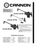
1
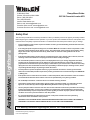
®
ENGINEERING COMPANY INC.
51 Winthrop Road
Chester, Connecticut 06412-0684
Phone: (860) 526-9504
Fax: (860) 526-4078
Internet: www.whelen.com
Sales e-mail: [email protected]
Canadian Sales e-mail: [email protected]
Customer Service e-mail: [email protected]
Clamp Mount Guide:
1997-99 Chevrolet Lumina APV
Safety First
Automotive: Lightbars
This document provides all the necessary information to allow your Whelen product to be properly and safely installed.
Before beginning the installation and/or operation of your new product, the installation technician and operator must
read this manual completely. Important information is contained herein that could prevent serious injury or damage.
•
Proper installation of this product requires the installer to have a good understanding of automotive electronics,
systems and procedures.
•
If mounting this product requires drilling holes, the installer MUST be sure that no vehicle components or other
vital parts could be damaged by the drilling process. Check both sides of the mounting surface before drilling
begins. Also de-burr any holes and remove any metal shards or remnants. Install grommets into all wire
passage holes.
•
If this manual states that this product may be mounted with suction cups, magnets, tape or Velcro®, clean the
mounting surface with a 50/50 mix of isopropyl alcohol and water and dry thoroughly.
•
Do not install this product or route any wires in the deployment area of your air bag. Equipment mounted or
located in the air bag deployment area will damage or reduce the effectiveness of the air bag, or become a
projectile that could cause serious personal injury or death. Refer to your vehicle owner’s manual for the air bag
deployment area. The User/Installer assumes full responsibility to determine proper mounting location, based
on providing ultimate safety to all passengers inside the vehicle.
•
For this product to operate at optimum efficiency, a good electrical connection to chassis ground must be
made. The recommended procedure requires the product ground wire to be connected directly to the NEGATIVE
(-) battery post.
•
If this product uses a remote device to activate or control this product, make sure that this control is located in
an area that allows both the vehicle and the control to be operated safely in any driving condition.
•
Do not attempt to activate or control this device in a hazardous driving situation.
•
This product contains either strobe light(s), halogen light(s), high-intensity LEDs or a combination of these
lights. Do not stare directly into these lights. Momentary blindness and/or eye damage could result.
•
Use only soap and water to clean the outer lens. Use of other chemicals could result in premature lens cracking
(crazing) and discoloration. Lenses in this condition have significantly reduced effectiveness and should be
replaced immediately. Inspect and operate this product regularly to confirm its proper operation and mounting
condition. Do not use a pressure washer to clean this product.
•
It is recommended that these instructions be stored in a safe place and referred to when performing
maintenance and/or reinstallation of this product.
•
FAILURE TO FOLLOW THESE SAFETY PRECAUTIONS AND INSTRUCTIONS COULD RESULT IN DAMAGE TO
THE PRODUCT OR VEHICLE AND/OR SERIOUS INJURY TO YOU AND YOUR PASSENGERS!
For warranty information regarding this product, visit www.whelen.com/warranty
©1999 Whelen Engineering Company Inc.
Form No.13435B (060402)
Page 1
INSTALLATION:
Mounting
Strap
Screw
Fig. 1
Tinnerman
Nut
1. Position the lightbar in the desired location. Refer to your
lightbar manual for the cable exit location, to be sure that the
lightbar is facing the proper direction.
Tension Bolt
2. With the location determined, adjust the two mounting feet
outwards so that they are resting on the surface outside the
roof’s gutter (See Fig. 1). To adjust the mounting feet, loosen the
two 3/8” bolts that secure the feet to the extrusion. Make sure
that both mounting feet are in full contact with the roof and not
hanging off the edge. Also confirm that there is at least 1/2”
clearance between the bottom of the lightbar and the roof of the
vehicle. When properly positioned, retighten these bolts to hold
the foot in place. Repeat this procedure for the remaining foot.
3. Open the driver’s side door. In the area directly below the
mounting foot, carefully separate the weatherstripping from the
vehicle using a razor blade or similar tool. Only separate enough
weatherstriping to accommodate the mounting strap. Repeat
this procedure for the passenger’s side of the vehicle.
Mounting
Foot
Mounting
Foot
(Bottom View)
Roof Surface
Gutter
1/2" MIN. CLEARANCE
Fig. 2
Weatherstrip
4. Insert the mounting strap through the mounting foot as shown in
Fig 3. Be sure that the strap fits flush against the mounting area
where it will be secured onto the vehicle. Insert the tension bolt
through the mounting strap and into the tinnerman nut on the
actuator plate. Tighten slightly with a long-shafted, Phillips
screwdriver. Repeat procedure for the passenger’s side.
5. Use the holes in the gutter end of the strap as a template to drill
two appropriately sized pilot holes through the strap and into the
vehicle. Repeat this for passenger’s side of the vehicle.
Actuator
6. Insert the supplied mounting screws into these holes and tighten
firmly. Repeat for passenger’s side of the vehicle.
Mounting
Strap
7. Now firmly tighten the tension bolt to secure the lightbar to
the vehicle.
62
8. Reposition
and
adhere
the
loose
weatherstriping to the mounting strap using
RTV.
Tinnerman
Nut
9
92
15/16 - 18 X 3“
Tension Bolt
LI
H
G
B
B
N
LE
E
H
W
T
The installation of this unit will
require drilling. It is absolutely
necessary to make sure that no
components could be damaged in
the process. If damage is possible,
select a different mounting location.
S
R
A
Y
CAUTION!
(2) 10 X 1/2“
PPHSMS
Page 2
Mounting Foot
Assembly
Fig. 3