1
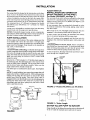
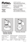
SEARS
OWNER'S
MANUAL
Model No. 390.304552
MODELNO.
390.304552
390.304612
390.304692
Model No. 390.304612
Model No. 390.304692
I:RRFTSMRN°
CAUTION:
Read and Follow
All Safety Rulesand
Operating Instructions
Before FirstUse of
This Product.
Save ThisManual For
Future Reference.
SUBMERSIBLE
SUMP PUMP
• Safety Instructions
• Installation
• Electrical
• Service
• Repair Parts
Sears, Roebuck and Co., Hoffman Estates, IL 60179
PRINTED
IN
U.S.A.
U.S.A.
Form NO.
F642-9811
(Rev, 10/22/02)
INTRODUCTION
CONTENTS
1NTROI)I
It 2Tl( )N/\\
SAFH'V
.
2
Plcasc
rczld
no\\
otlr
ill_,trtlctiolls
this
",','ill help
pttmp;
2
vitc
lronl
...........................
3
thai
rt'suh
...............................
i
in O111" %varrallt)
..............................................
5
H.ECFRICAI
PARTS
..................
......................................
INSTALLATION
St:RVICIi
,\ RRA NIS
........................................................
FULL
ONE
it
It will
Irom
als(i
C;lUSeS
bcl_.)rc
yotl
yotl
obtain
help
y(lu
We
CallnOl
install
and
flail valuc
and
avoid
needless
COlttrol
;llld
list
VOllr
gooti scr
service
costs
cautlol
cover
(_7
YEAR
WARRANTY
ON
CRAFTSMAN
® SUBMERSIBLE
SUMP
PUMPS
For one year from the date of purchase, Sears will repair or replace this pump, free of charge, if defective ha material or
workmanship.
LIMITED
WARRANTY
After one year and through
part. YOU pay for labor.
ON CRAFTSMAN*
two years from the date of purchase,
This warranty does not cover repairs or replacement
and operate this pump according
to the instructionsin
1/3-HP SUBMERSIBLE SUMP PUMPS
Sears will furnish,
parts necessary because
the owner's manual.
free of charge,
of abuse
a replacement
or negligence
LIMITATION
OF LIABILITY
SEARS WILL NOT BE LIABLE FOR LOSS OR DAMAGE TO PROPERTY OR ANY INCIDENTAL
pgrt for 7any defective
including
failure to install, adjust
oR CONSEQUENTIAL
LOSS OR
DIPENSE FROM PROPERTY DAMAGE DUE DIRECTLy OR INDIRECTLY FROM THE USE OF _
PRODUCT
.....
Some states do not allow the exclusion
or limitation Of incidental or consequential
damages, so the above _tation
or exclusion
n0t_apply to you.
WARRANTY SERVICE IS AVAILABLE BY SIMPLY CONTACTING THE NEAREST SEARS SERVICE CENTER/DEPARTMENT
IN THE
UNITED STATES.
Tlfis warranty
This warranty
•
:
applies only whife the product is in use in the UMt_ S ta_ _
gives you specific iegal rights and you mayalso!ia,
de0flfe/figlxswhichvary_m
Sears,
Roebuck
and
Co.,
De]p_
817
read
manual
or
_This
on
and
follow
following
injury!
signal
I
injury,
words
death
[ _.WARNING
injury,
L.
& cAuTioN-,:
_
minor
The
personal
word
portant
and he alert
about
not
about
death
hazards
injury
property
hazards
or major
warns
" about
NOTICE
but
in
_es,
hazards
or property
indicates
related
to the potemial
that will
that
damage
special
or can
damage
will
or
if ignored.
cause
installing
pump
which
plumbing
and electrical
power
cord
pump
to
plug.
cool for 20 minutes
before
Modem
motors
are designed
tures.
water
or put
C. Ground
proceed
as follows
outlet
box
before
plug is pulled, let pump
attempting
to operate
to work
on it.
at high tempera-
codes
your
finger
the electrical
changing
shocks,
fuses.
To reduce
DO NOT stand in
in the fuse socket.
outlet
box.
D. Use only an individual
branch
circuit
with
Fault Circuit
Interrupter
(GFCI) protected
outlet
are im-
to hazards.
national
pump
After
if ignored.
instructions
1. To avoid risk nf serious bodily injury and property damage,
read safety instructions carefully before installing pump.
when
&Disconnect
pulling
seri-
Electrically powered stamp pumps normally give many years of
trouble-free
service when correctly installed, maintained,
and
used. However, unusual circumstances
(interruption
of power
to the pump, dirt/debris
in the sump, flooding that exceeds the
pump's capacity, electrical or mechanical
failure in the pump,
etc.) may prevent your pump from functioning normally. To pre
vent possible water damage due to flooding, consult your local
Sears store about installing a secondary sump pump or a DC
backup sump pump
See "Service", Page 5, for information
about common sump pump problems and remedies.
2. Follow local and/or
shocks,
B. Take extreme
care when
the chance
of fatal electrical
cause
can
OPERATION
per-
ff ignored.
that will
property
serious
AND
_*v_nn._uj
TO avoid fatal
if pump
needs
servicing:
for personal
cause
damage
IL 60179
this
alert symbol.
When you see this symor in this manual,
h)ok for one of the
or major
]warns
ous personal
instructions
3.
warns
sonal
safety
pump.
is the safety,
on your pump
bol
all
state to state.
'¢gA, HO_
RULES FOR SAFE INSTALLATION
Carefully
may
for
cord
a Ground
grounded
plug.
4. Never
run pump
dry. To do so can damage internal
parts,
overheat
the pump
(which
can cause burns to people
handling or servicing
the pump),
and will void the warranty!
5. DO NOT
been put
other
6. This
tions
attempt
to oil the pump
motor.
A special
oil has
into the motor housing
at the factory;
use of any
oil will void the warranty
pump
only.
ADDITIONAL
HATERIALS
is recommended
Pump
water
and could
for use
only with
damage
in permanent
the pump.
installa-
this pump.
INSTALLATION
Sump/Utility
Pump Hose Kit, SEARS Stock No. 27909, containing 24' (7.3M) of 1-1/4" flexible plastic pipe, a 1-1/4" plastic adapter and a stainless steel clamp.
Check
Valve, SEARS Stock
No. 2789.
INSTALLATION
THE SUMP
The sump should be located at the lowest place in the basement or area to be drained. Floor drains from other areas in
the basement
may be tiled into the sump. Drain tile around
a house foundation
can also be tiled into the sump, effectively removing
water and relieving pressure
frorn this area.
A suitable sump can be a 20" or 24" (500_10mm)
sewer tile.
The minimum
size is 12" (305mm)
in diameter
for Models
390.304552
and 390.304612;
10" (254mm)
for Model
390.304692.
A sump
Consult
cover is desirable to exclude refuse from the sump.
local code for sump cover specifications.
NOTICE:
and sump
all refuse.
Periodically
inspect pump, system components,
for debris and foreign objects. Keep sump free of
Perform routine maintenance
as required.
PUMP
INSTALLATION
Set the pump on the bottom of the sump, making sure that
is sits solidly and is level. Be sure there is enough
space
around the pump to allow the switch free movement
as the
sump water level changes.
Pump should not be installed on
clay, earth, or sand surfaces.
[& CAUTION } Risk of flooding.
If a flexible discharge
hose
is used, pump may move around in sump when motor starts.
If it moves far enough so that the switch hits the side of the
sump, the switch may stick and prevent pump from starting.
Make sure that pump is secured
so that it cannot
walk
around in sump.
FLOAT SWITCH
INSTALLATION
AND
OPERATION
(Models 390.304552
and 390.304612;
For Model 390.304692,
see Page 7)
The automatic
float switch is factory mounted
on the pump
and preset for a pumping
range of approximately
7". Tether
length is factory preset at 3-1/2" (89mm) (see Figure 3). Do
not change tether length.
Be sure automatic
float can swing freely through
its entire
arc without
interference
from pump, piping, sump wall or
any other object.
When sump is dry, the watertight
hanging in a downward
position
tape to seal threads
in plastic
pipe.
is
As water comes into the sump, the automatic
float switch
rises to an upward position and the pump starts.
Water will continue
to be pumped
hanging in the downward
position
stop.
IAWARNING]Risk
of electric
until the float switch is
again, when pump will
shock.
Before
installation,
check your local electrical
codes. To avoid personal
when servicing your pump, be sure that the power
connected
from both the pump and the float switch.
injury
is dis-
To check operation,
fill sump with water
ation through
one complete
cycle.
oper-
and observe
Grounded
Electrical
Hose Kit No. 27909 includes
1-1/4" flexible plastic pipe for
the discharge
pipe. Run discharge
pipe to the nearest sewer
outlet or other point of disposal. Use the most direct route
and the fewest turns and elbows possible.
Make sure that
pump cannot move around in sump pit.
Use teflon
only.
automatic
float switch
and the pump is off.
Make sure
pump cannot
move fn sump
Hand tighten
NOTE: To avoid backflow
into sump when pump shuts off,
install a Check Valve, SEARS Stock No. 2789, in threaded discharge port of pump. Be sure arrow on check valve body
points
away from the pump.
This Sears check
valve is
equipped
with an air bleed hole to prevent airlocking pump.
If using any other check valve, drill 1/8" (3.2mm)
hole in
dishcharge
pipe just above pump body but below check
valve to prevent air locks.
<t-----
20" to 24"
500 to 610rnm)
1/4'
Sump_Cover
(6ram)
\
FIGURE
Basement
2 - Models
390.304552
and
390.304612
Floor
Sewer Tile
(st
(89mm)
FIGURE
DO
20" I
(500 to 610ram)
FIGURE
I
NOT
3 - Tether
ALLOW
Length
PUMP
Pump should not be allowed
To do so voids the warranty
TO
RUN
DRY
to run dry prior to shutting
and could ruin the pump.
off.
ELECTRICAL
ELECTRICAL
CONNECTIONS
I_ikWARNINGIRisk of electric
shock.
This pump
is supplied with a grounding
conductor
and grounding-type
attachment
plug. To reduce
the risk of electric
shock,
be certain
that it is connected
only
to a properly
grounded,
grounding-type
receptacle.
The Sump Pump has a 3-prong
is used to ground the pump to
The third prong should never
outlet should be the 3-prong,
hal ground.
A separate
ommended.
Testing
UL Listed
electric plug. The third prong
prevent possible fatal shock.
be removed.
Your electrical
polarized
type with an inter-
15 amp individual branch electrical circuit
DO NOT USE AN EXTENSION
CORD.
Analyzer
FIGURE
Outlet j
4A
Face Plate
is rec-
For Ground
utlet
For your safety, check your outlet for ground
using an
Underwriters
Laboratory
Listed Circuit Analyzer.
(Figure
4A). A Circuit Analyzer will tell you by a pattern of fights if
the power,
neutral,
and ground
wires are correctly
connected to your outlet. It can also be used to check other outlets in your home. A Circuit Analyzer is available in the Sears
Electrical Department.
Grounding
BO×
_
Bare Copper Wire
to Cold Water Pipe
Face
Plate
Screw
FIGURE
Outlet
4B
If your outlet is not grounded,
install a copper wire (at least
14 gauge) from the outlet box, as shown in Figure 4B, to a
metal cold water pipe. Use ground clamp on pipe.
IMPORTANT:
The cold water pipe you use as a ground
must have metal continuity
to electrical ground.
If continuity is interrupted
by plastic, rubber, or other electrical
insulators; such as hoses, fittings, washers or gaskets (including
water meter or pump),
a metal bypass must be used. Any
electrically
insulated connector
should be jumped (as shown
in Figure 4C), with a length of No. 4 wire clamped securely
at both ends.
C,amp
Clamp
Metal Water Pipe
FIGURE
Automatic
Thermal
Overload
Meter
4C
Protection
Generator
This pump motor has a built-in automatic
thermal overload
protector,
ff the motor overheats,
the protector
will open
and cut off power to the motor before the heat damages it
internally.
The overload
will reset automatically
and the
pump will restart after the pump cools down below the danger point.
Sizing
Below is the minimum
Engine-Generator
Watt rating required to power
this pump motor. Any additional
loads,
such as lights, must be added to the listed load and the generator sized accordingly.
Pump
[AWARNING_ DO NOT attempt
motor
motor
could
when
pump
to work
on the pump
or
if the overload
seems
to have
tripped.
The
may restart without
warning
at any time. You
be injured
and the pump
damaged
if it starts
you are working
on it. Remove
all power
from
before
attempting
to work on it.
DO NOT attempt to repair a non-operational
sump
Take it to Sears for service by a qualified technician.
pump.
4
Minimum Wa_
Model
HP
Rating of Generator
390.304552
390,304612
390.304692
1_
1/3
1/3
3000
4500
4500
SERVICE
General
Pump
[_WARNING]Risk
of electric
shock.
When
servicing
pump
always
disconnect
power
to electrical
outlet
and remove
pump
electric
cord from outlet.
1. If pump
1. NOTICE:
for loose plug at electric
b. Check for blown fuses
fuse box/circuit
breaker
c. Be sure nothing
float switch.
interferes
with
circuit
breakers
at
of automatic
but blows fuses/trips
circuit
After disconnecting
power
to pump, remove
it from
sump. Remove the plate from the bottom of the pump
and make sure that the impeller turns freely. Remove any
debris obstructing
impeller.
If pump still does not operate correctly,
return
it to your nearest
Sears Service
Department
for repairs.
3. Pump
rims, but does not empty
a. Clean pump
intake
sump:
sttmp faster than the pump
e. Be sure check
pipe is not plugged
valve is operating
For
Model
and 390.304612;
390.304692,
see Page 7)
NOTICE: Float must be able to swing through
its complete
arc without
interference
from sidewall of sump, plumbing
or any other object.
pump
2. Remove
Unscrew
power
cord from receptacle.
tether clamp screw and slide cord from
tee-handle from pump body.
clamp.
3. insert new cord in tether clamp in same location on cord
with respect
to float. Install tee-handle
in pump and
tighten.
4. Tighten
can
c. Be sure vertical distance from pump discharge
outlet
to discharge pipe outlet does not exceed specifications.
See chart below.
d. Be sure discharge
REPLACEMENT
tether
clamp
screw.
5. Check sump pump operation by filling sump with water
and observing operation
through one complete
cycle.
screen.
b. Water may be entering
discharge
it.
motor will void war-
and screws.
SWITCH
1. Unplug
breakers:
baseplate
(Models 390.304552
d. If a, b, and c above check OK, plug in a light that you
know works, ff it fights, take your pump to Sears for
service. If it doesn't light, the electrical circuit is faulty;
consult a licensed electrician.
2. Pump starts,
3. Re-install
FLOAT
action
to disassemble
2. To clean impeller, remove eight screws holding baseplate
to motor assembly. Clean/replace
impeller as necessary.
To remove impeller, unscrew
it from motor shaft.
outlet.
or tripped
box.
Attempting
ranty.
does not operate:
a. Check
Cleaning
[ _, WARNING] Failure
to check
in sump can lead to Lmproper
pump failure
and flooding.
installation
operation,
with
water
premature
or frozen.
correctly.
[_'WARNING_Risk
of electric
shock.
Unplug
pump before attempting
to service
or remove
any component.
1. The motor in the unit is sealed in oil. No additional lubrication
is necessary.
2. NOTICE: Disassembly
of the motor assembly
will void
warranty. It might also cause internal leakage and damage
to the unit. If motor fails, replace entire pump.
3. Keep inlet screen
clean and free of all foreign
objects.
SPECIFICATIONS
Stock
Number
HP
Maximum
Amps
30455
1/4
8.5
8-1/2"(216)
8-1/2"(216)
30461
1/3
13.0
9"(229)
30469
1/3
13.0
9"(229)
Dimensions in inches (mm)
Width
Length
Height
GPM (Idmin.) at Vertical Pumping Distance in Feet (M)
5'(1.6)
10'(3)
15'(4.6)
9-3/4"(248)
38(144)
27(102)
11(41.6)
6-1/2"(165)
11-1/2"(292)
50(189)
41(155)
6-1/2"(165)
11-1/2"(292)
50(189)
41(155)
18'(5.5)
20'(6.1)
28(106)
15(57)
3(11.4)
28(106)
15(57)
3(11.4)
REPAIR PARTS
Model
390.304552
Model
390.304612
Outlet
Outlet
Float Switch
Piggy-back
Plug
Float Switch
Piggy-back
Plug
Pump
Plug
Pump
Plug
10
8
PARTS LIST
Key
No.
Part
Description
390.304552
Part No.
t
U30-956ZP
2
3
4
5
6
7
8
9
10
PS1-30P
RP0000917
U30-912PS
PS1-32P
CC003_13
PS117-123P
U30-955SS
PS117-54-TSU
Pump Body Screw #8 x 1/2 Type A
(7 Req.)
Lower Pump Body
Impeller
Screw, Motor Housing (4 Required)
Upper Pump Body
Motor
Cable Clamp
Float Switch
Cable Clamp Screw #8 x 5/8 Type A
Power Cord Assembly and Plug
** If motor fails, replace entire pump.
PARTS
Key
No,
LIST
Part
Description
390.304612
Part No.
1
U30-934ZP
2
PS4-17P
3
4
RP0000911A
PS1-29P
5
**
6
7
8
9
CC0030-13
U30-955SS
U30-912PS
PS117-123P
Motor Assembly Complete
Cable Clamp
Cable Clamp Screw #8 x 5/8 Type A
Screw (4 Required)
Float Switch
10
PS117-53-TSU
Power Cord Assembly and Plug
Baseplate Screw #8 x 1/2 Type A
(8 Req.)
Baseplate
Impeller
Volute
** If motor fails, replace entire pump.
REPAIR PARTS
Vertical
Switch
Model
390.304692
Assembly
Floal Swdch
hogs=rig
M0untlng
--
Pump
Plug
__
InsetDrawing
Houtlng
Slip the Iloat
ono he rod
(_Screw
1he rod
stop onto the
end
of the
/
rod
8
_\
_Z_
Rod
7
11
Attach
the
s_tch
lo
the pump as showm
6
3
I
I
[_, CAUTION ] Make sure pin holds float rod in switch
housing; otherwise pump will not shut off.
To check switch operation, run pump through one complete cycle after installation.
IA WARNh,_
Risk of electrical shock. Can burn or kill.
Plug pump and switch into a grounded electrical outlet
only.
PARTS UST
390.304692
Part No.
Key
No.
Part
Description
1
2
3
4
5
6
U30-934ZP
PS4-17P
RP0000911A
U30-912PS
PS1-29P
P$3C-3
I_aseplateScrew #8 x 1/2 Type A (8 Req.)
Baseplate
Impeller
Screw (4 Required)
Volute
Pin
7
**
Motor Assembly Complete
8
9
10
11
12
13
14
PS117-53-TSU
RP0005248
PS28-18
PS28-17
U30-955PS
PS19-18SS
PS17-66
PowErCord and Plug
Roat Stop
Roar
Rod
Clamp Screw #8 x _/8 Type A (3 ReqO
Bracket
Switch Housing
** If motor fails, mpl_ ce entire pump.
I
SEARS
OWNER'S
MANUAL
[RRFTSMRN °
SUBMERSIBLE
SUMP PUMP
Model No.
390.304552
390.304612
390.304692
Forthe repair or replacementpartsyou need
Call7 am - 7 pm, 7 daysa week
1-800-366-PART
(1-800-366-7278)
Forin-homemajorbrandrepair service
Call24 hours a day, 7 days a week
1-800-4-REPAIR
The model number of
your Submersible Sump
Pump will be found on a
plate attached to the side
of the motor.
When requesting service
or ordering parts, always
give the following
information:
• Product Type
• Model Number
(1-800-473-7247)
Forthe locationof a
SearsRepairServiceCenter in yourarea
Call24 hours a day, 7 days a week
1-800.488.1222
For informationon purchasinga Sears
MaintenanceAgreementor to inquire
aboutan existingAgreement
call 9 am - 5 pro, Monday-Saturday
A
1-800-827-6655
• Part Number
• Part Description
America's
Repair Sp6cialists
Sears, Roebuck and Co., Hoffman Estates, IL 60179
U.S.A.