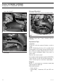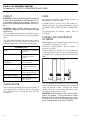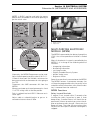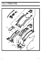
1
Smr-2004 BRP suppl 3d rfi ang.FH8 Thu Sep 23 10:31:37 2004 Page 1 C M Y CM MY CY CMY K 2004 Shop Manual Supplement 3DTM RFITM BOMBARDIER RECREATIONAL PRODUCTS INC. Legal deposit: National Library of Quebec National Library of Canada 2004 All rights reserved. No parts of this manual may be reproduced in any form without the prior written permission of Bombardier Recreational Products Inc. ©Bombardier Recreational Products Inc. 2004 Technical Publications Bombardier Recreational Products Inc. Valcourt (Quebec) Canada Printed in Canada ®TMRegistered trademarks of Bombardier Recreational Products Inc. or its affiliates. * Bombardier is a trademark of Bombardier Inc., used under license. SEA-DOO® ROTAX® BOMBARDIER* LUBE® XP-STM Synthetic Injection Oil XP-STM Synthetic Blend Injection Oil XP-STM Mineral Injection Oil Sea-Doo Synthetic Grease Sea-Doo LKTM DESSTM O.P.A.S.TM TOPSTM O.T.A.S.TM 3DTM This document contains the trademarks of the following companies: Knight’s Spray-Nine† is a trademark of Korkay System Ltd GTX† is a trademark of Castrol Ltd. Used under license Loctite® is a trademark of Loctite Corporation Snap-on® is a trademark of Snap-on Tools Corporation Gelcote® is a trademark of Gelcote International Limited Molykote© is a trademark of Dow Corning Corporation Snap-on© is a trademark of Snap-on Tools Corporation AMP© is a trademark of Tyco Electronics Corporation TABLE OF CONTENTS NOTE: Refer to shop manual for sections NOT covered in this supplement. SAFETY NOTICE .. .. ... .. .. ... .. .. ... .. .. ... .. .. ... .. .. ... .. .. ... .. .. ... .. .. ... .. .. ... .. .. ... .. .. .. III INTRODUCTION .. .. ... .. .. ... .. .. ... .. .. ... .. .. ... .. .. ... .. .. ... .. .. ... .. .. ... .. .. ... .. .. ... .. .. .. V HULL IDENTIFICATION NUMBER (H.I.N.) . . .. . . .. . . .. . . .. . . .. . . .. . . .. . . .. . . .. . . .. . . .. . . .. . . .. . . .. . . .. . . .. . . .. . . ENGINE IDENTIFICATION NUMBER (E.I.N.) . . . .. . . .. . . .. . . .. . . .. . . .. . . .. . . .. . . .. . . .. . . .. . . .. . . .. . . .. . . .. . . .. . . V V 02 03 04 MAINTENANCE 01 – PERIODIC INSPECTION CHART.. . . .. . . .. . . .. . . .. . . .. . . .. . . .. . . .. . . .. . . .. . . .. . . .. . . .. . . .. . . .. . . .. . . .. . . .. . . 04 – STORAGE . .. . . .. . . .. . . .. . . .. . . .. . . .. . . .. . . .. . . .. . . .. . . .. . . .. . . .. . . .. . . .. . . .. . . .. . . .. . . .. . . .. . . .. . . .. . . .. . . .. . . 1 5 ENGINE DRAINING . . . . . . . . . . . . . . . . . . . . . . . . . . . . . . . . . . . . . . . . . . . . . . . . . . . . . . . . . . . . . . . . . . . . . . . . . . . . . . . . . . . . . . . . . . . . . . . . . . PROPULSION SYSTEM. . . . . . . . . . . . . . . . . . . . . . . . . . . . . . . . . . . . . . . . . . . . . . . . . . . . . . . . . . . . . . . . . . . . . . . . . . . . . . . . . . . . . . . . . . . . . . FUEL SYSTEM. . . . . . . . . . . . . . . . . . . . . . . . . . . . . . . . . . . . . . . . . . . . . . . . . . . . . . . . . . . . . . . . . . . . . . . . . . . . . . . . . . . . . . . . . . . . . . . . . . . . . . . . COOLING SYSTEM FLUSHING AND ENGINE INTERNAL LUBRICATION . . . . . . . . . . . . . . . . . . . . . . . . . . . . . . . . . . . . . . BATTERY . . . . . . . . . . . . . . . . . . . . . . . . . . . . . . . . . . . . . . . . . . . . . . . . . . . . . . . . . . . . . . . . . . . . . . . . . . . . . . . . . . . . . . . . . . . . . . . . . . . . . . . . . . . . . . WATERCRAFT CLEANING. . . . . . . . . . . . . . . . . . . . . . . . . . . . . . . . . . . . . . . . . . . . . . . . . . . . . . . . . . . . . . . . . . . . . . . . . . . . . . . . . . . . . . . . . . . ANTIFREEZING PROTECTION . . . . . . . . . . . . . . . . . . . . . . . . . . . . . . . . . . . . . . . . . . . . . . . . . . . . . . . . . . . . . . . . . . . . . . . . . . . . . . . . . . . . . . ANTICORROSION TREATMENT . . . . . . . . . . . . . . . . . . . . . . . . . . . . . . . . . . . . . . . . . . . . . . . . . . . . . . . . . . . . . . . . . . . . . . . . . . . . . . . . . . . . 5 5 6 6 7 7 7 8 TROUBLESHOOTING 01 – TROUBLESHOOTING CHART . . .. . . .. . . .. . . .. . . .. . . .. . . .. . . .. . . .. . . .. . . .. . . .. . . .. . . .. . . .. . . .. . . .. . . .. . . .. . . 9 ENGINE WILL NOT START . . . . . . . . . . . . . . . . . . . . . . . . . . . . . . . . . . . . . . . . . . . . . . . . . . . . . . . . . . . . . . . . . . . . . . . . . . . . . . . . . . . . . . . . . . O.T.A.S.TM SYSTEM NOT FUNCTIONAL . . . . . . . . . . . . . . . . . . . . . . . . . . . . . . . . . . . . . . . . . . . . . . . . . . . . . . . . . . . . . . . . . . . . . . . . . . . BILGE PUMP DOES NOT WORK . . . . . . . . . . . . . . . . . . . . . . . . . . . . . . . . . . . . . . . . . . . . . . . . . . . . . . . . . . . . . . . . . . . . . . . . . . . . . . . . . . . WARNING LIGHT IS ON/ENGINE NOT RUNNING . . . . . . . . . . . . . . . . . . . . . . . . . . . . . . . . . . . . . . . . . . . . . . . . . . . . . . . . . . . . . . . . STEERING POLE IS HEAVIER THAN USUAL . . . . . . . . . . . . . . . . . . . . . . . . . . . . . . . . . . . . . . . . . . . . . . . . . . . . . . . . . . . . . . . . . . . . . . STEERING POLE IS STIFFER THAN USUAL . . . . . . . . . . . . . . . . . . . . . . . . . . . . . . . . . . . . . . . . . . . . . . . . . . . . . . . . . . . . . . . . . . . . . . . ENGINE CANNOT REACH MAXIMUM RPM (LACK OF PERFORMANCE). . . . . . . . . . . . . . . . . . . . . . . . . . . . . . . . . . . . . . 9 9 9 10 10 10 10 ENGINE (2-STROKE) 07 – EXHAUST SYSTEM. . .. . . .. . . .. . . .. . . .. . . .. . . .. . . .. . . .. . . .. . . .. . . .. . . .. . . .. . . .. . . .. . . .. . . .. . . .. . . .. . . .. . . .. . . 11 REMOVAL . . . . . . . . . . . . . . . . . . . . . . . . . . . . . . . . . . . . . . . . . . . . . . . . . . . . . . . . . . . . . . . . . . . . . . . . . . . . . . . . . . . . . . . . . . . . . . . . . . . . . . . . . . . . 13 INSTALLATION . . . . . . . . . . . . . . . . . . . . . . . . . . . . . . . . . . . . . . . . . . . . . . . . . . . . . . . . . . . . . . . . . . . . . . . . . . . . . . . . . . . . . . . . . . . . . . . . . . . . . . . 17 06 ENGINE MANAGEMENT (RFI) 02 – DIAGNOSTIC PROCEDURES . . .. . . .. . . .. . . .. . . .. . . .. . . .. . . .. . . .. . . .. . . .. . . .. . . .. . . .. . . .. . . .. . . .. . . .. . . .. . . 23 ADVANCED DIAGNOSTIC . . . . . . . . . . . . . . . . . . . . . . . . . . . . . . . . . . . . . . . . . . . . . . . . . . . . . . . . . . . . . . . . . . . . . . . . . . . . . . . . . . . . . . . . . . . 23 05 – ADJUSTMENT.. . . .. . . .. . . .. . . .. . . .. . . .. . . .. . . .. . . .. . . .. . . .. . . .. . . .. . . .. . . .. . . .. . . .. . . .. . . .. . . .. . . .. . . .. . . .. . . 25 THROTTLE CABLE ADJUSTMENT .. . . .. . . .. . . .. . . .. . . .. . . .. . . .. . . .. . . .. . . .. . . .. . . .. . . .. . . .. . . .. . . .. . . .. . . 25 09 COOLING SYSTEM 01 – CIRCUIT, COMPONENTS AND CARE . .. . . .. . . .. . . .. . . .. . . .. . . .. . . .. . . .. . . .. . . .. . . .. . . .. . . .. . . .. . . .. . . .. . . 27 CIRCUIT . . . . . . . . . . . . . . . . . . . . . . . . . . . . . . . . . . . . . . . . . . . . . . . . . . . . . . . . . . . . . . . . . . . . . . . . . . . . . . . . . . . . . . . . . . . . . . . . . . . . . . . . . . . . . . . COMPONENTS. . . . . . . . . . . . . . . . . . . . . . . . . . . . . . . . . . . . . . . . . . . . . . . . . . . . . . . . . . . . . . . . . . . . . . . . . . . . . . . . . . . . . . . . . . . . . . . . . . . . . . . CARE . . . . . . . . . . . . . . . . . . . . . . . . . . . . . . . . . . . . . . . . . . . . . . . . . . . . . . . . . . . . . . . . . . . . . . . . . . . . . . . . . . . . . . . . . . . . . . . . . . . . . . . . . . . . . . . . . . TOWING THE WATERCRAFT IN WATER. . . . . . . . . . . . . . . . . . . . . . . . . . . . . . . . . . . . . . . . . . . . . . . . . . . . . . . . . . . . . . . . . . . . . . . . . . . 28 28 28 28 I TABLE OF CONTENTS 10 FUEL SYSTEM 01 – FUEL CIRCUIT .. . . .. . . .. . . .. . . .. . . .. . . .. . . .. . . .. . . .. . . .. . . .. . . .. . . .. . . .. . . .. . . .. . . .. . . .. . . .. . . .. . . .. . . .. . . .. . . 31 11 LUBRICATION SYSTEM (2-STROKE) 02 – OIL INJECTION PUMP. . . .. . . .. . . .. . . .. . . .. . . .. . . .. . . .. . . .. . . .. . . .. . . .. . . .. . . .. . . .. . . .. . . .. . . .. . . .. . . .. . . .. . . 33 ADJUSTMENT. . . . . . . . . . . . . . . . . . . . . . . . . . . . . . . . . . . . . . . . . . . . . . . . . . . . . . . . . . . . . . . . . . . . . . . . . . . . . . . . . . . . . . . . . . . . . . . . . . . . . . . . 33 12 ELECTRICAL SYSTEM 02 – CHARGING SYSTEM .. . . .. . . .. . . .. . . .. . . .. . . .. . . .. . . .. . . .. . . .. . . .. . . .. . . .. . . .. . . .. . . .. . . .. . . .. . . .. . . .. . . .. . . 35 GENERAL . . . . . . . . . . . . . . . . . . . . . . . . . . . . . . . . . . . . . . . . . . . . . . . . . . . . . . . . . . . . . . . . . . . . . . . . . . . . . . . . . . . . . . . . . . . . . . . . . . . . . . . . . . . . . 35 TESTING PROCEDURE . . . . . . . . . . . . . . . . . . . . . . . . . . . . . . . . . . . . . . . . . . . . . . . . . . . . . . . . . . . . . . . . . . . . . . . . . . . . . . . . . . . . . . . . . . . . . . 35 03 – STARTING SYSTEM . .. . . .. . . .. . . .. . . .. . . .. . . .. . . .. . . .. . . .. . . .. . . .. . . .. . . .. . . .. . . .. . . .. . . .. . . .. . . .. . . .. . . .. . . 39 GENERAL . . . . . . . . . . . . . . . . . . . . . . . . . . . . . . . . . . . . . . . . . . . . . . . . . . . . . . . . . . . . . . . . . . . . . . . . . . . . . . . . . . . . . . . . . . . . . . . . . . . . . . . . . . . . . 39 04 – INSTRUMENTS AND ACCESSORIES . .. . . .. . . .. . . .. . . .. . . .. . . .. . . .. . . .. . . .. . . .. . . .. . . .. . . .. . . .. . . .. . . .. . . 41 GENERAL . . . . . . . . . . . . . . . . . . . . . . . . . . . . . . . . . . . . . . . . . . . . . . . . . . . . . . . . . . . . . . . . . . . . . . . . . . . . . . . . . . . . . . . . . . . . . . . . . . . . . . . . . . . . . VEHICLE CONTROL MODULE (VCM). . . . . . . . . . . . . . . . . . . . . . . . . . . . . . . . . . . . . . . . . . . . . . . . . . . . . . . . . . . . . . . . . . . . . . . . . . . . . . MULTI-PURPOSE ELECTRONIC MODULE (MPEM) . . . . . . . . . . . . . . . . . . . . . . . . . . . . . . . . . . . . . . . . . . . . . . . . . . . . . . . . . . . . . . INSPECTION. . . . . . . . . . . . . . . . . . . . . . . . . . . . . . . . . . . . . . . . . . . . . . . . . . . . . . . . . . . . . . . . . . . . . . . . . . . . . . . . . . . . . . . . . . . . . . . . . . . . . . . . . . 41 41 45 47 05 – DESS (CARBURETED AND RFI ENGINES) . . . .. . . .. . . .. . . .. . . .. . . .. . . .. . . .. . . .. . . .. . . .. . . .. . . .. . . .. . . .. . . 49 DESS KEY PROGRAMMING.. . . .. . . .. . . .. . . .. . . .. . . .. . . .. . . .. . . .. . . .. . . .. . . .. . . .. . . .. . . .. . . .. . . .. . . .. . . .. . . 49 13 PROPULSION 01 – JET PUMP . .. . . .. . . .. . . .. . . .. . . .. . . .. . . .. . . .. . . .. . . .. . . .. . . .. . . .. . . .. . . .. . . .. . . .. . . .. . . .. . . .. . . .. . . .. . . .. . . .. . . 51 02 – DRIVE SYSTEM. . . .. . . .. . . .. . . .. . . .. . . .. . . .. . . .. . . .. . . .. . . .. . . .. . . .. . . .. . . .. . . .. . . .. . . .. . . .. . . .. . . .. . . .. . . .. . . 53 REMOVAL . . . . . . . . . . . . . . . . . . . . . . . . . . . . . . . . . . . . . . . . . . . . . . . . . . . . . . . . . . . . . . . . . . . . . . . . . . . . . . . . . . . . . . . . . . . . . . . . . . . . . . . . . . . . 54 04 – VARIABLE TRIM SYSTEM . . .. . . .. . . .. . . .. . . .. . . .. . . .. . . .. . . .. . . .. . . .. . . .. . . .. . . .. . . .. . . .. . . .. . . .. . . .. . . .. . . 57 REMOVAL . . . . . . . . . . . . . . . . . . . . . . . . . . . . . . . . . . . . . . . . . . . . . . . . . . . . . . . . . . . . . . . . . . . . . . . . . . . . . . . . . . . . . . . . . . . . . . . . . . . . . . . . . . . . 58 DISASSEMBLY . . . . . . . . . . . . . . . . . . . . . . . . . . . . . . . . . . . . . . . . . . . . . . . . . . . . . . . . . . . . . . . . . . . . . . . . . . . . . . . . . . . . . . . . . . . . . . . . . . . . . . . 58 ASSEMBLY . . . . . . . . . . . . . . . . . . . . . . . . . . . . . . . . . . . . . . . . . . . . . . . . . . . . . . . . . . . . . . . . . . . . . . . . . . . . . . . . . . . . . . . . . . . . . . . . . . . . . . . . . . . 58 14 STEERING SYSTEM 01 – STEERING SYSTEM . .. . . .. . . .. . . .. . . .. . . .. . . .. . . .. . . .. . . .. . . .. . . .. . . .. . . .. . . .. . . .. . . .. . . .. . . .. . . .. . . .. . . .. . . 59 INSPECTION. . . . . . . . . . . . . . . . . . . . . . . . . . . . . . . . . . . . . . . . . . . . . . . . . . . . . . . . . . . . . . . . . . . . . . . . . . . . . . . . . . . . . . . . . . . . . . . . . . . . . . . . . . 62 DISASSEMBLY . . . . . . . . . . . . . . . . . . . . . . . . . . . . . . . . . . . . . . . . . . . . . . . . . . . . . . . . . . . . . . . . . . . . . . . . . . . . . . . . . . . . . . . . . . . . . . . . . . . . . . . 63 ASSEMBLY . . . . . . . . . . . . . . . . . . . . . . . . . . . . . . . . . . . . . . . . . . . . . . . . . . . . . . . . . . . . . . . . . . . . . . . . . . . . . . . . . . . . . . . . . . . . . . . . . . . . . . . . . . . 73 02 – ALIGNMENT . . .. . . .. . . .. . . .. . . .. . . .. . . .. . . .. . . .. . . .. . . .. . . .. . . .. . . .. . . .. . . .. . . .. . . .. . . .. . . .. . . .. . . .. . . .. . . .. . . 79 16 HULL/BODY 01 – ADJUSTMENT AND REPAIR . . . .. . . .. . . .. . . .. . . .. . . .. . . .. . . .. . . .. . . .. . . .. . . .. . . .. . . .. . . .. . . .. . . .. . . .. . . .. . . 81 CLEANING . . . . . . . . . . . . . . . . . . . . . . . . . . . . . . . . . . . . . . . . . . . . . . . . . . . . . . . . . . . . . . . . . . . . . . . . . . . . . . . . . . . . . . . . . . . . . . . . . . . . . . . . . . . . BILGE VENT TUBES . . . . . . . . . . . . . . . . . . . . . . . . . . . . . . . . . . . . . . . . . . . . . . . . . . . . . . . . . . . . . . . . . . . . . . . . . . . . . . . . . . . . . . . . . . . . . . . . . REAR ACCESS COVER . . . . . . . . . . . . . . . . . . . . . . . . . . . . . . . . . . . . . . . . . . . . . . . . . . . . . . . . . . . . . . . . . . . . . . . . . . . . . . . . . . . . . . . . . . . . . . KART SEAT . . . . . . . . . . . . . . . . . . . . . . . . . . . . . . . . . . . . . . . . . . . . . . . . . . . . . . . . . . . . . . . . . . . . . . . . . . . . . . . . . . . . . . . . . . . . . . . . . . . . . . . . . . . 17 81 81 81 81 TECHNICAL DATA 06 – 3D RFI MODEL .. . . .. . . .. . . .. . . .. . . .. . . .. . . .. . . .. . . .. . . .. . . .. . . .. . . .. . . .. . . .. . . .. . . .. . . .. . . .. . . .. . . .. . . .. . . .. . . 83 18 WIRING DIAGRAM 01 – WIRING DIAGRAMS . .. . . .. . . .. . . .. . . .. . . .. . . .. . . .. . . .. . . .. . . .. . . .. . . .. . . .. . . .. . . .. . . .. . . .. . . .. . . .. . . .. . . .. . . 87 VCM CONNECTORS . . . . . . . . . . . . . . . . . . . . . . . . . . . . . . . . . . . . . . . . . . . . . . . . . . . . . . . . . . . . . . . . . . . . . . . . . . . . . . . . . . . . . . . . . . . . . . . . . 87 II SAFETY NOTICE SAFETY NOTICE This manual has been prepared as a guide to correctly service and repair the 2004 3DTM RFITMSEA-DOO watercraft. This Shop Manual Supplement must be used in conjunction with the 2004 Sea-doo Shop Manual (P/N 219 100 192). Refer to this manual when a particular system is not covered in this Supplement. This edition was primarily published to be used by watercraft mechanical technicians who are already familiar with all service procedures relating to BRP made watercraft. Mechanical technicians should attend training courses given by BRP Training Dept. Please note that the instructions will apply only if proper hand tools and special service tools are used. This Shop Manual Supplement uses technical terms which may be slightly different from the ones used in the Parts Catalog. It is understood that this manual may be translated into another language. In the event of any discrepancy, the English version shall prevail. The content depicts parts and/or procedures applicable to the particular product at time of writing. Service and Warranty Bulletins may be published to update the content of this manual. Make sure to read and understand these. In addition, the sole purpose of the illustrations throughout the manual, is to assist identification of the general configuration of the parts. They are not to be interpreted as technical drawings or exact replicas of the parts. The use of BRP parts is most strongly recommended when considering replacement of any component. Dealer and/or distributor assistance should be sought in case of doubt. The engines and the corresponding components identified in this document should not be utilized on product(s) other than those mentioned in this document. WARNING Torque wrench tightening specifications must be strictly adhered to. Locking devices (ex.: locking tab, self-locking fasteners, etc.) must be installed or replaced with new ones. If the efficiency of a locking device is impaired, it must be renewed. WARNING Unless otherwise specified, engine should be turned OFF and cold for all maintenance and repair procedures. This manual emphasizes particular information denoted by the wording and symbols: WARNING Identifies an instruction which, if not followed, could cause serious personal injury including possibility of death. CAUTION: Denotes an instruction which, if not followed, could severely damage vehicle components. NOTE: Indicates supplementary information needed to fully complete an instruction. Although the mere reading of such information does not eliminate the hazard, your understanding of the information will promote its correct use. Always use common shop safety practice. III SAFETY NOTICE BRP disclaims liability for all damages and/or injuries resulting from the improper use of the contents. We strongly recommend that any services be carried out and/or verified by a highly skilled professional mechanic. It is understood that certain modifications may render use of the vehicle illegal under existing federal, provincial and state regulations. IV INTRODUCTION INTRODUCTION This Shop Manual Supplement covers the following BRP made SEA-DOO® 2004 3DTM RFITM watercraft models. ENGINE TYPE MODEL NUMBER 3D RFI 787 RFI 6157 3D RFI International 787 RFI 6158 MODEL ENGINE IDENTIFICATION NUMBER (E.I.N.) The Engine Identification Number is located on the upper crankcase on PTO side. HULL IDENTIFICATION NUMBER (H.I.N.) It is located on platform at the rear of watercraft. F01D87A 1 1. Engine Identification Number (E.I.N.) 1 F22L06A 1. Hull Identification Number (H.I.N.) The Hull Identification Number is composed of 12 digits: ZZN12345L495 Serial number* F00A0CB Manufacturer Model year Year of production Month of production *A letter may also be used as a digit. V Section 02 MAINTENANCE Subsection 01 (PERIODIC INSPECTION CHART) PERIODIC INSPECTION CHART The schedule should be adjusted according to operating conditions and use. NOTE: The chart gives an equivalence between number of hours and months/year. Perform the maintenance operation to whatever time comes first. IMPORTANT: Schedule for watercraft rental operations or higher number of hour use, will require greater frequency of inspection and maintenance. DESCRIPTION I: Inspect, verify, clean, adjust, lubricate. Replace if necessary C: Clean L: Lubricate R: Replace INTERVAL FIRST 10 HOURS EVERY 25 HOURS OR 3 MONTHS EVERY 50 HOURS OR 6 MONTHS EVERY 100 HOURS OR 1 YEAR GENERAL Lubrication/corrosion protection (1) L Support and rubber mount I I Seals and fasteners I I Exhaust system fasteners (5) I I ENGINE Expansion pipe I RAVE valve (5) C C Counterbalance shaft oil level I I Spark plug (5) I (4) R Ignition timing (5) I COOLING SYSTEM Flushing Hose and fasteners C (3) I Engine drain tubes I I (1) FUEL SYSTEM Throttle cable (1) I Fuel injection system sensors (except throttle body) (5) I Throttle body and TPS (5) I Fuel lines, fuel rail, fittings, check-valve, relief valve and fuel system pressurization (5) I Air intake silencer fit/tightness I I Fuel tank straps I I smr2004-3D I I I 1 Section 02 MAINTENANCE Subsection 01 (PERIODIC INSPECTION CHART) DESCRIPTION I: Inspect, verify, clean, adjust, lubricate. Replace if necessary C: Clean L: Lubricate R: Replace INTERVAL FIRST 10 HOURS EVERY 25 HOURS OR 3 MONTHS EVERY 50 HOURS OR 6 MONTHS EVERY 100 HOURS OR 1 YEAR LUBRICATION SYSTEM Oil injection pump (5) I I Oil lines I I Oil filter I I Oil reservoir straps I R ELECTRICAL SYSTEM Electrical connections and fastening (ignition system, starting system, fuel injectors, etc.) (5) I I I MPEM and ECU mounting support/fasteners Digitally Encoded Security System and safety lanyard/post I Monitoring beeper I I Battery support/fasteners I I Steering cable I I Steering pole I I Handlebar and adjuster operation I I “Moto” seat I I I STEERING SYSTEM O.T.A.S.tm SYSTEM O.T.A.S. system operation I I PROPULSION SYSTEM Drive shaft protection hose Seal carrier I (2) L L Driveshaft/impeller splines L VTS (Variable Trim System) I Jet pump reservoir oil R Jet pump cover pusher I I R I Impeller shaft seal 2 R (4) Impeller and impeller/wear ring clearance I (2) Water intake grate I (2) smr2004-3D Section 02 MAINTENANCE Subsection 01 (PERIODIC INSPECTION CHART) DESCRIPTION I: Inspect, verify, clean, adjust, lubricate. Replace if necessary C: Clean L: Lubricate R: Replace INTERVAL FIRST 10 HOURS EVERY 25 HOURS OR 3 MONTHS EVERY 50 HOURS OR 6 MONTHS EVERY 100 HOURS OR 1 YEAR HULL/BODY Bailer pick-ups, check for obstructions I Kart seat (if so equipped) I Hull I I I I (1) Every 10 hours in salt water use. (2) These items have to be initially checked after 25 hours. Thereafter, servicing to be made as specified in this chart. (3) Daily flushing in salt water or foul water use. (4) Replace at 150 hours or after 2 years, whichever comes first. (5) Emission-related component. smr2004-3D 3 Section 02 MAINTENANCE Subsection 04 (STORAGE) STORAGE 2 ENGINE DRAINING Disconnect the water supply hose used to cool the magneto. It features a quick connect fitting. Press both tabs and pull fitting in order to disconnect hose. This hose is located at the bottom of the magneto cover beside the engine support. F17E0BA 1 1. Fitting 2. Hose 1 CAUTION: Water in heat exchanger system must be free to flow out. Should water freeze in engine, severe damage will occur. Reconnect hose when done. PROPULSION SYSTEM F22E02A 1. Press tabs here and disconnect hose Water should flow out of the fitting (magneto cooling circuit) and hose (crankcase heat exchanger). Push and hold hose against bilge so that draining can take place. NOTE: It may be necessary to position the end of the hose in a lower area of the bilge to allow proper drainage. smr2004-3D Jet Pump Lubricant in impeller shaft reservoir should be drained. Reservoir should be cleaned and refilled with SEA-DOO synthetic 75W90 GL5 polyester oil. Refer to JET PUMP in the Shop Manual for proper procedure. CAUTION: Use only SEA-DOO jet pump oil or equivalent synthetic gear oil, otherwise component service life could be reduced. Do not mix oil brands or types. 5 Section 02 MAINTENANCE Subsection 04 (STORAGE) Seal Carrier Remove rear access cover. Lubricate seal carrier of drive shaft support with synthetic grease. Stop lubricating when grease is just coming out of seal. 1 WARNING Fuel is inflammable and explosive under certain conditions. Always work in a well ventilated area. Do not smoke or allow open flames or sparks in the vicinity. Fuel tank may be pressurized, slowly turn cap when opening. When fueling, keep watercraft level. Do not overfill or top off the fuel tank and leave watercraft in the sun. As temperature increases, fuel expands and might overflow. Always wipe off any fuel spillage from the watercraft. Periodically inspect fuel system. COOLING SYSTEM FLUSHING AND ENGINE INTERNAL LUBRICATION F22J05A 1. Grease seal carrier FUEL SYSTEM Inspect fuel hoses. Replace damaged hoses or clamps if necessary. Sea-Doo Fuel Stabilizer (P/N 413 408 600) or equivalent should be added in fuel tank to prevent fuel deterioration. Follow manufacturer's instructions for proper use. Cooling system has to be flushed with fresh water to prevent salt, sand or dirt accumulation which will clog water passages. Engine must be lubricated to prevent corrosion on internal parts. For proper procedure, refer to FLUSHING AND LUBRICATION in the Shop Manual. Follow instructions for RFI models. NOTE: On the 3D RFI, the hose adapter is located on the right hand side on the jet pump support. CAUTION: Fuel stabilizer should be added prior to engine lubrication to ensure fuel system components protection against varnish deposits. Fill up fuel tank completely. Ensure there is no water inside fuel tank. CAUTION: Should any water be trapped inside fuel tank, severe internal damage will occur to the fuel injection system. 1 F22J01A 1. Hose adapter 6 smr2004-3D Section 02 MAINTENANCE Subsection 04 (STORAGE) BATTERY Engine and Tuned Pipe Disconnect battery cables. Remove rear access panel and engine cover. Lock steering pole in upright position with the holder. WARNING Battery BLACK negative cable must be disconnected FIRST. Disconnect vent tube from battery. Unfasten battery support. Using battery strap, remove battery. For battery cleaning and storage, refer to CHARGING SYSTEM in the Shop Manual. WARNING Always install steering pole holder while working in the engine compartment. Install hose pinchers and disconnect hoses at the following locations. WATERCRAFT CLEANING Refer to STORAGE in the Shop Manual. ANTIFREEZING PROTECTION 2 In cool regions (where freezing point may be encountered), cooling system should be filled with pure antifreeze. CAUTION: Antifreeze must be fed in cooling system. Otherwise remaining water will freeze. If antifreezing is not performed adequately engine/exhaust system may freeze and cause severe damage. Always use ethylene glycol antifreeze containing corrosion inhibitors specifically recommended for aluminum engines. CAUTION: Use only undiluted antifreeze (100% concentration). The pre-mixed antifreeze available from Bombardier Recreational Products Inc. is not suitable for this particular application. Its concentration will be reduced when mixed with remaining water trapped in water jackets. Always use ethylene glycol antifreeze containing corrosion inhibitors specifically recommended for aluminum engines. Never use antifreeze for RV (recreational vehicles). NOTE: When available, it is recommended to use biodegradable antifreeze compatible with internal combustion aluminum engines. This will contribute to protect the environment. NOTE: The engine will not have to run during this operation but should have been ran before, to exhaust as much water as possible, from cooling system components. NOTE: This procedure requires approximately 2.5 L (2.6 U.S. qt) of antifreeze. smr2004-3D 1 F22E03A 1. Pinch Engine cylinder drain hose 2. Pinch Engine heat exchanger drain hose 2 1 3 F22E04A 1. Disconnect water supply hose 2. Pinch water outlet hose 3. Install a temporary hose to engine fitting 7 Section 02 MAINTENANCE Subsection 04 (STORAGE) Insert a funnel into the temporary hose and pour antifreeze in engine until the colored solution appears at the cooling system bleed outlet. Use a container to recover the water/antifreeze. Expansion Pipe and Muffler Disconnect the tuned pipe water supply hose at T-fitting. 1 F07E0LA F22E06A TYPICAL 1. Disconnect hose from T-fitting Insert a funnel into the hose. Raise the hose as high as possible and pour 1.2 L (1.3 U.S. qt) of antifreeze. CAUTION: It is important to keep the hose as high as possible so the antifreeze can reach the end of the expansion pipe. Reconnect hose to the T-fitting. Complete Cooling System F22L0HA 1 COOLING SYSTEM BLEED OUTLET 1. Recover water/antifreeze from this outlet Place a container at rear of watercraft to recover the water/antifreeze from the vehicle hose adapter. Remove the 2 hose pinchers from the engine drain hoses. Most of the antifreeze will drain out when removing the hose pinchers. Use a container to recover it. DISPOSE ANTIFREEZE AS PER YOUR LOCAL LAWS AND REGULATIONS. 8 NOTE: For the above engine and exhaust system procedures, although most of the antifreeze drained out, it has mixed with any water in the water jackets. At preseason preparation, flush out the remaining antifreeze from cooling system prior to using the watercraft. ANTICORROSION TREATMENT Refer to STORAGE in the Shop Manual. smr2004-3D Section 03 TROUBLESHOOTING Subsection 01 (TROUBLESHOOTING CHART) TROUBLESHOOTING CHART The following is provided to help in diagnosing the probable source of troubles. It is a guideline and should not be assumed to show all causes for all problems. Only the systems not covered in the Shop Manual are outlined. Refer to the Shop Manual for the other systems. ENGINE WILL NOT START OTHER OBSERVATION Engine does not turn over/no beep/indicator light cluster not working Engine does not turn over/no beep/indicator light cluster working POSSIBLE CAUSE REMEDY Discharged battery or bad connections Check battery state of charge and battery posts Defective DESS post Check DESS post. Refer to INSTRUMENTS AND ACCESSORIES Burnt 20 A fuse Check fuse No power at VCM Check for battery voltage on VCM wire connector pin 6-G Bad ground Check for continuity with ground on VCM wire connector pin 6-D Defective VCM Replace No power at MPEM Check voltage on MPEM wire connector pin 3-26 O.T.A.S.TM SYSTEM NOT FUNCTIONAL OTHER OBSERVATION Warning light flashes POSSIBLE CAUSE REMEDY Defective O.T.A.S. solenoid circuit Check PU/WH, BK wires and connections. Defective O.T.A.S. solenoid Check. Refer to INSTRUMENTS AND ACCESSORIES Defective VCM Replace BILGE PUMP DOES NOT WORK OTHER OBSERVATION Warning light flashes smr2004-3D POSSIBLE CAUSE REMEDY Defective bilge pump circuit Check BW and BK wires. Check connections Defective bilge pump Check/replace Defective VCM Replace 9 Section 03 TROUBLESHOOTING Subsection 01 (TROUBLESHOOTING CHART) WARNING LIGHT IS ON/ENGINE NOT RUNNING OTHER OBSERVATION Beeper signal (4 short beeps every 3 seconds) POSSIBLE CAUSE Safety lanyard on DESS post REMEDY Remove safety lanyard from DESS post STEERING POLE IS HEAVIER THAN USUAL OTHER OBSERVATION POSSIBLE CAUSE REMEDY Steering pole return spring adjustment Adjust Broken steering pole return spring) Replace STEERING POLE IS STIFFER THAN USUAL OTHER OBSERVATION POSSIBLE CAUSE Dirty/damage parts REMEDY Inspect/clean/replace mounting bridge, clamps, tube and spring guide ENGINE CANNOT REACH MAXIMUM RPM (LACK OF PERFORMANCE) OTHER OBSERVATION POSSIBLE CAUSE REMEDY Increased exhaust noise/smoke in bilge Broken expansion pipe Inspect/replace. Refer to EXHAUST SYSTEM Water inside expansion pipe Broken expansion pipe (water jacket) Inspect/replace. Refer to EXHAUST SYSTEM Melted exhaust hose/fitting Exhaust restriction or external water leak from exhaust cooling system Inspect/repair 10 smr2004-3D Section 04 ENGINE (2-STROKE) Subsection 07 (EXHAUST SYSTEM) EXHAUST SYSTEM 3D RFI 3 48 Nm (35 lbfft) 13 1 Loctite 592 Loctite 592 11 Nm (97 lbfin) 17 26 Nm (19 lbfft) 17 2 11 Loctite 592 5 18 24 15 17 26 Nm (19 lbfft) 18 17 Loctite 518 39 Nm (29 lbfft) 11 4 12 26 Nm (19 lbfft) Loctite 243 Loctite 592 16 25 40 Nm (30 lbfft) 7 Loctite 518 Molykote 111 F22D03S smr2004-3D 11 Section 04 ENGINE (2-STROKE) Subsection 07 (EXHAUST SYSTEM) 19 High temperature RTV sealant 22 23 21 8 14 10 9 High temperature RTV sealant 20 12 Loctite 5150 11 High temperature RTV sealant F22D04S 12 smr2004-3D Section 04 ENGINE (2-STROKE) Subsection 07 (EXHAUST SYSTEM) REMOVAL Tuned Pipe Remove engine cover then lift and lock steering pole. Remove air intake silencer. NOTE: In some of the following illustrations, flame arrester and throttle body were removed for clarity only. Disconnect hoses from tuned pipe no. 1. F22D05B Remove: – screws no. 3. F22D05A F22D05C F22D07A Loosen clamp no. 2 then slide rearward to release the joint. smr2004-3D 13 Section 04 ENGINE (2-STROKE) Subsection 07 (EXHAUST SYSTEM) – screw no. 4 and 5. Exhaust Manifold Disconnect hose from exhaust manifold no. 25. F22D08A F22D05D Remove screws no. 7 then withdraw exhaust manifold. Expansion Pipe F22D09A – tuned pipe. Inspection Do the test with the watercraft tied on a trailer in water. NOTE: Performing the test with a garden hose connected on the flushing fitting of jet pump support would not supply enough pressure in the exhaust system to properly detect faulty joints in some cases. Remove rear access panel. Start engine and bring engine speed to 5000 RPM. Check for leaks in joint area of expansion pipe. If there is exhaust gas or water leak, replace pipe. Removal NOTE: It is not necessary to remove tuned pipe to pull expansion pipe out. Remove/disconnect: – flame arrester – throttle body. Disconnect ATS and APS sensors. 14 smr2004-3D Section 04 ENGINE (2-STROKE) Subsection 07 (EXHAUST SYSTEM) 2 WARNING 1 Pay attention not to bend injection oil cable or throttle cable. – hoses from rear fittings no. 11 1 F22D0DA 1. Hose moved away 2. Foam support F22D0CA 1. Disconnect hoses from fittings here – – – – small clamp no. 12 from muffler no. 15 strap no. 13 from muffler clamps no. 21 and no. 22 from exhaust hoses T-fitting no. 23 with hoses and resonator no. 14 then move remaining hose away to get access to foam support 3 1 2 F22D0EA INITIAL POSITION OF FOAM Proceed as follows: – Tip top of foam forward as shown F22D06B 3 1. Disconnect small clamp here 2. Large clamp (ref) 3. Disconnect those clamps – foam support under expansion pipe. smr2004-3D 15 Section 04 ENGINE (2-STROKE) Subsection 07 (EXHAUST SYSTEM) F22D0HA F22D0FA – rotate left/right as shown Muffler Pull muffler out. Inspect muffler, shell and boot condition. Resonators Upper Resonator Remove strap no. 8, loosen clamps no. 9 then pull out resonator no. 10. F22D0GA – pull foam out NOTE: If tuned pipe is still in place, firmly push muffler rearward to disengage expansion pipe from tuned pipe. – pull out expansion pipe forward. Wiggle it to disengage from muffler F22D0AA Lower Resonator Loosen clamp no. 11 then pull out resonator no. 12. 16 smr2004-3D Section 04 ENGINE (2-STROKE) Subsection 07 (EXHAUST SYSTEM) F22D0BA INSTALLATION Installation is essentially the reverse of removal procedures. However, pay particular attention to the following. Tuned Pipe CAUTION: Torque wrench tightening specifications must be strictly adhered to. Locking devices (ex.: locking tabs, elastic stop nuts, self-locking fasteners, etc.) must be installed or replaced with new ones where specified. If the efficiency of a locking device is impaired, it must be renewed. NOTE: Loosen all pipe supports from engine before installing tuned pipe. Ensure rubber bushings no. 17 and sleeve no. 18 are not damaged and are properly installed into tuned pipe supports. CAUTION: Damage to bushings and/or sleeve will eventually cause stress to tuned pipe and may cause cracking. Apply Loctite 518 on both sides of gasket no. 24. Make sure that gasket no. 24 is properly located on exhaust manifold prior to finalizing pipe installation. Torquing Sequence CAUTION: Torque the tuned pipe in accordance with the following sequence, otherwise serious engine damage may occur. smr2004-3D 17 Section 04 ENGINE (2-STROKE) Subsection 07 (EXHAUST SYSTEM) NOTE: Press the pipe support on the engine before torquing the pipe support bolts. 26 Nm (19 lbfft) 10 26 Nm 11 (19 lbfft) 26 Nm (19 lbfft) 13 1 Nm 1 (9 lbfin) 26 Nm (19 lbfft) 12 40 Nm 15 (30 lbfft) 9 48 Nm (35 lbfft) 7 5 6 Nm (53 lbfin) 3 2 6 Nm (53 lbfin) 4 6 48 Nm (35 lbfft) 8 40 Nm 14 (30 lbfft) F15D06S 18 smr2004-3D Section 04 ENGINE (2-STROKE) Subsection 07 (EXHAUST SYSTEM) Expansion Pipe and Muffler Apply Loctite 592 on threads of fittings no. 11. Tighten fittings to 5 N•m (44 lbf•in) then position as per following illustration. Do not screw more than 1 turn while positioning. Do not unscrew to reposition. 90° 90° F22D0IA 30° F22D0JA Pressurize the wall jacket to 103 kPa (15 PSI) through the fittings. No leak should occur. Position muffler no. 15 in its location. Do not install the strap and the small clamp yet. Insert expansion pipe in its position. WARNING Pay attention not to bend injection oil cable or throttle cable. Loosely install a NEW clamp no. 2. CAUTION: Those clamp type are not designed to be removed and reinstalled many times. Reinstalling a used clamp is likely to fail. Reinstall hoses to T-fittings no. 11. Rear hoses can be connected on any fitting. Ensure to keep the same hose routing (inverted U shape). CAUTION: If hoses length or routing were changed, water ingestion might occur when watercraft tips over. Strongly push expansion pipe toward muffler to insert it into bellow no. 16. smr2004-3D 19 Section 04 ENGINE (2-STROKE) Subsection 07 (EXHAUST SYSTEM) To ensure pipe end is well inserted in muffler, measure the distance as shown in the following illustration. A F22D0KS A. 322 mm (12.68 in) Insert foam under expansion pipe. Ensure foam is not against muffler bellow. Position foam under bracket edge so that it is properly retained. – Ensure there is a gap between clamp ends. Otherwise, try another clamp. 2 A F22D0MA F22D0LA 1 1. Bracket edge 2. Foam A. Clamp ends must have a gap here Ensure there is a gap between hose at front T-fitting and fuel tank. Rotate expansion pipe to position its T-fittings vertically. CAUTION: If T-fittings were not installed vertically, water ingestion might occur when watercraft tips over. Tighten front clamp no. 2 as follows. – Ensure to align expansion pipe with tuned pipe so that their ends are in contact all around. – Tighten clamp while maintaining expansion pipe and tuned pipe together. – Torque clamp to 11 N•m (97 lbf•in). 20 smr2004-3D Section 04 ENGINE (2-STROKE) Subsection 07 (EXHAUST SYSTEM) A 2 1 F22D0PA F22D0NA A. Gap between hose and fuel tank Ensure there is a gap between muffler and bilge/cooling hose. 1. All around 2. Opposite vertical lines Finalizing Assembly WARNING Ensure that tubes and hoses are properly routed away from any rotating, moving, heating or vibrating parts. Also ensure that hot parts are properly positioned away from any part that can be damaged by the heat. A A F22D0OA Reinstall remaining parts. Depress and release the throttle lever. It should operate smoothly and return to its initial position without any hesitation. Reset the Closed TPS. Refer to ENGINE MANAGEMENT. A. Gap between muffler and bilge/cooling hose Tighten small bellow clamp no. 12. Ensure bellow is not trapped between foam and expansion pipe. Ensure exhaust hose no. 67 rests against fuel tank. Exhaust Outlet Prior to installing exhaust outlet no. 20, apply Loctite 5150 as shown. smr2004-3D 21 Section 06 ENGINE MANAGEMENT (RFI) Subsection 02 (DIAGNOSTIC PROCEDURES ) DIAGNOSTIC PROCEDURES ADVANCED DIAGNOSTIC VCK (Vehicle Communication Kit) Electrical Connections Connect VCK components and open the software B.U.D.S. 1 2 After all connections are done, connect the safety lanyard to the DESS post to activate the communication. IMPORTANT: When using the software B.U.D.S., ensure that the protocol matching the connection used is properly selected in “MPI” under “Choose protocol” as per the following chart. TYPE OF CONNECTION ADAPTER TO USE Through DESS post DESS adapter (P/N 529 035 684) Through 6-pin DESS connector RFI DESS adapter (P/N 278 001 978) PROTOCOL TO CHOOSE DESS F12H0BA TYPICAL 1. 6-pin adapter (P/N 529 035 679) 2. DESS adapter (P/N 529 035 684) NOTE: It is also possible to disconnect the connector located under the top cover of steering pole and install the RFI DESS adapter (P/N 278 001 978). 1 F22R07A 1. RFI DESS adapter smr2004-3D 23 Section 06 ENGINE MANAGEMENT (RFI) Subsection 05 (ADJUSTMENT) ADJUSTMENT 2 1 THROTTLE CABLE ADJUSTMENT NOTE: For throttle cable replacement, refer to STEERING SYSTEM. Right throttle cable adjustment is to be done at the adjuster on top of steering pole. However, first ensure adjuster at throttle body is fully screwed in. F22K09A 1. Steering pole at its lowest position 2. Handlebar at its lowest position and in straight ahead position Fully depress throttle lever and hold. Throttle lever stopper should almost contact throttle body. To ensure there is free play, apply a light pressure on the throttle plate, a slight play should be obtained. 1 1 F22R06A 1. Adjuster fully screwed in Otherwise, set it. Whenever adjuster is set at the throttle body, the throttle cable must be adjusted at the OTAS solenoid. Refer to INSTRUMENTS AND ACCESSORIES for the procedure. Position steering pole and handlebar to their lowest position. Place handlebar in the straight ahead position. F22G03A 1. Free play here CAUTION: Improper cable adjustment will cause strain on cable and/or damage cable bracket or throttle lever at handlebar. smr2004-3D 25 Section 06 ENGINE MANAGEMENT (RFI) Subsection 05 (ADJUSTMENT) When released, throttle lever must have a free play of 1 - 7 mm (1/32 - 9/32 in). To adjust cable, remove top cover of steering pole. Refer to STEERING SYSTEM. Set cable with the adjuster. 1 F22R05A 1. Cable adjuster NOTE: When throttle cable is adjusted from this adjuster, there is no need to readjust throttle cable at the OTAS solenoid. Reinstall removed parts. Reset the Closed TPS. Ensure the OTAS system works adequately. Refer to INSTRUMENTS AND ACCESSORIES. NOTE: It is not necessary to adjust the oil injection pump cable after throttle cable adjustment. It is not changed when throttle cable is adjusted. 26 smr2004-3D Section 09 COOLING SYSTEM Subsection 01 (CIRCUIT, COMPONENTS AND CARE) CIRCUIT, COMPONENTS AND CARE 3D RFI Cooling System Indicator hose (CSI) Tuned pipe water jacket supply hose Magneto heat exchanger inlet hose Cylinder head outlet hose Magneto view To crankcase heat exchanger inlet To tunel pipe Magneto heat exchanger outlet hose Loctite 592 Hull Loctite 592 Hose protector Crankcase heat exchanger outlet hose Engine water outlet hose Engine drain hose (from cylinders) Tuned pipe water-jacket supply hose (cone) Anti-rollover bypass hose (expansion pipe water jackets) CAUTION: Do not modify routing or hose length Loctite 592 Loctite 592 Hose adapter (flushing) Bypass hose (tuned pipe/ expansion pipe water jackets) F22E05S smr2004-3D Engine water supply hose Water injection in muffler 27 Section 09 COOLING SYSTEM Subsection 01 (CIRCUIT, COMPONENTS AND CARE) CIRCUIT CARE CAUTION: All hoses and fittings of the cooling system have calibrated inside diameters to assure proper cooling of the engine. Always replace using appropriate Bombardier part number. For flushing purposes, the cooling system is equipped with a hose adapter. A garden hose is used to flush the whole system by backwash. For flushing procedure, refer to FLUSHING AND LUBRICATION in the Shop Manual. For winterization of cooling system, refer to STORAGE. CAUTION: Never modify cooling system arrangement, otherwise serious engine damage could occur. The tuned pipe and the expansion pipe have a water jacket to control the exhaust system temperature. The water from the expansion pipe water jacket is injected into the muffler to cool it (last part of the expansion pipe water jacket has internal holes). TECHNICAL DATA TYPE TLCS (Total Loss Cooling System). COOLANT FLOW Flow from impeller housing (no water pump). TEMPERATURE CONTROL Calibrated outlet fittings (no thermostat). SYSTEM BLEEDING Self-bleed type (hose at uppermost point of circuit). SYSTEM DRAINING Self-drain type (hose at lowest point of circuit). SYSTEM FLUSHING Hose adapter. MONITORING BEEPER Turns on at 86 - 94°C (187 - 201°F). COMPONENTS Due to the dry pipe design (no water injection in tuned pipe) of this watercraft, there is no water flow regulator valve as found on other 787 RFI watercraft. 28 TOWING THE WATERCRAFT IN WATER Special precautions should be taken when towing a Sea-Doo 3D watercraft in water. Maximum recommended towing speed is 24 km/h (15 MPH). When towing your watercraft in water, pinch the water supply hose from the jet pump housing to the engine with a large hose pincher (P/N 529 032 500). F01B23A This will prevent the cooling system from filling which may lead to water being injected into and filling the exhaust system. Without the engine running there isn't any exhaust pressure to carry the water out the exhaust outlet. CAUTION: Failure to do this may result in damage to the engine. If you must tow a stranded watercraft in water and do not have a hose pincher be sure to stay well below the maximum towing speed of 24 km/h (15 MPH). smr2004-3D Section 09 COOLING SYSTEM Subsection 01 (CIRCUIT, COMPONENTS AND CARE) Snugly install the hose pincher on the water supply hose as shown in the following illustration. NOTE: Pinch the hose with the red tape. 1 2 3 F22E01A 1. Engine water supply hose 2. Hose pincher this side of T-fitting 3. T-fitting CAUTION: When finished towing the watercraft, the hose pincher must be removed before operating it. smr2004-3D 29 Section 10 FUEL SYSTEM Subsection 01 (FUEL CIRCUIT) FUEL CIRCUIT Fuel Tank Removal and Installation The engine removal is necessary to remove fuel tank. Disconnect battery. To have access to the rear fuel tank holding strap, remove exhaust hoses with the resonator. 1 WARNING Always disconnect BLACK negative cable first. Pull out both vent tubes. 1 F22D06A 1. Loosen clamps and pull out hoses with resonator Detach all 3 fuel tank straps. Pull out fuel tank. Installation is essentially the reverse of removal procedure. WARNING Whenever doing any type of repair on watercraft or if any components of the fuel system are disconnected, a pressure test must be done before starting engine. Ensure to verify fuel line ends for damage. Always cut damaged end before reinstallation. F22J0AA Remove ignition coils. Disconnect fuel hoses. Refer to RFI ENGINE MANAGEMENT in the Shop Manual. Disconnect fuel pump wire harness. Siphon fuel tank. Remove electric fuel pump. smr2004-3D 31 Section 10 FUEL SYSTEM Subsection 01 (FUEL CIRCUIT) Fuel System Pressurization High Pressure Test (fuel pump circuit) Proceed as follows: – Fill up fuel tank (recommended but not mandatory). – Install a hose pincher (P/N 295 000 076) on fuel tank vent hose. – Connect pump gauge tester (P/N 529 021 800) to air inlet hose fitting. NOTE: This pump is included in the ENGINE LEAK TESTER KIT (P/N 295 500 352). Install safety lanyard on DESS post to activate fuel pump. Check for any leakage at fuel rail, injectors and fuel hose. 1 2 F22F01A 1. Connect pump to air inlet fitting 2. Install hose pincher on this hose – Pressurize fuel system to 34 kPa (5 PSI). – If pressure is not maintained locate leak and repair/replace component leaking. To ease leak search spray a solution of soapy water on components, bubbles will indicate leak location. NOTE: The system must maintain a pressure of 34 kPa (5 PSI) during 10 minutes. Never pressurize over 34 kPa (5 PSI). WARNING If any leak is found, do not start the engine and wipe off any fuel leakage. Do not use electric powered tools on watercraft unless system has passed pressure test. Remove hose pincher from fuel tank vent hose. Make sure pressure is dropping on pump gauge tester. NOTE: Pressure drop indicates that relief valve and the outlet fitting are not blocked. Remove the pump gauge tester from the air inlet hose fitting. 32 smr2004-3D Section 11 LUBRICATION SYSTEM (2-STROKE) Subsection 02 (OIL INJECTION PUMP) OIL INJECTION PUMP ADJUSTMENT NOTE: On the 3D RFI, if the throttle cable is readjusted, it does not change the oil injection pump adjustment. CAUTION: Proper oil injection pump adjustment is very important. Any delay in the opening of pump can result in serious engine damage. The oil injection pump should be adjusted as follows; the mark on the pump lever should be offset (richer side) by 1 mm (.039 in) with the other mark on the pump housing. 1 F07G02C 1. Mark on pump lever offset by 1 mm (.039 in) smr2004-3D 33 Section 12 ELECTRICAL SYSTEM Subsection 02 (CHARGING SYSTEM) CHARGING SYSTEM GENERAL Fuse If the battery is regularly discharged, check fuse condition. The rectifier/regulator could be the culprit of a blown fuse. To check, simply disconnect the rectifier/regulator from the circuit. If the fuse still burns, check for a defective wire. CAUTION: Do not use a higher rated fuse as this cause severe damage. NOTE: Since charging current flows through the main fuse, check its condition. The main fuse is located beside the VCM. 1 2 1 F22H06A 1. 2-pin connector – Insert a jumper wire across the black wire terminals of open connectors. – Connect an ammeter across the RED wires of open connectors. F22H02A BK 1. VCM 2. Main fuse RE 1 TESTING PROCEDURE NOTE: First, ensure that battery is in good condition prior to performing the following tests. 2 BK Rectifier/Regulator STATIC TEST: CONTINUITY Due to internal circuitry, there is no static test available. RE F22H07A DYNAMIC TEST 1. Jumper wire 2. Ammeter Current Test Proceed as follows: Unplug the 2-pin rectifier/regulator connector. – Start engine. – Bring engine to approximately 6000 RPM. smr2004-3D 35 Section 12 ELECTRICAL SYSTEM Subsection 02 (CHARGING SYSTEM) – Note the reading. This is the current supplied by the regulator. – Remove jumper wire and reconnect the 2-pin connector. Remove the main fuse from its holder: – Connect an ammeter across the fuse holder. 1 2 F22H08A 1. Main fuse holder 2. Ammeter – Start engine. – Bring engine to approximately 6000 RPM. – Note the reading. This is the current actually consumed – Reinstall fuse. Substract the consumed current from the regulator current. This gives the current supplied by the regulator. It should be within 3 - 4 A. CHARGING CURRENT = CURRENT FROM REGULATOR - CONSUMED CURRENT If charging current is below specification, check magneto output. If the magneto output is good, try another rectifier/regulator. Recheck charging current. If still out of specification, the fuel pump or the MPEM current draw is too high. If charging current exceeds specification, replace the rectifier/regulator. If multimeter reads over 15 volts, regulator is defective. Replace it. NOTE: If it is continually necessary to add distilled water to the battery, this indicates an over voltage situation, requiring replacement of the rectifier/ regulator. If, on the other hand, the battery will not stay charged, the problem can be any of the charging circuit components. If these all check good, you would be accurate in assuming the problem to be in the rectifier/regulator. If there is no charging at the battery with the preceding voltage test, the following test can also be performed. Disconnect the connector housing of the rectifier/regulator. Using an appropriate terminal remover (Snap-on TT600-4), remove the RED and BLACK wires from the tab housing of the rectifier/regulator. Reconnect the connector housing. Connect the positive probe of a multimeter to the RED wire and the negative probe to the BLACK wire. Set multimeter to Vdc scale. BK 1 RE 2 3 BK RE F22H09A 1. Connector removed on rectifier/regulator side 2. Wires connected to remaining connector 3. Voltmeter DC Voltage Test Proceed as follows: – Start engine. – Connect a multimeter to battery posts. Set multimeter to Vdc scale. – Bring engine to approximately 5500 RPM. 36 smr2004-3D Section 12 ELECTRICAL SYSTEM Subsection 02 (CHARGING SYSTEM) Start and rev engine to 3500 RPM. The obtained value should be between 12 and 25 Vdc. NOTE: If the rectifier/regulator is within the specification, either the MPEM or wiring harness between the rectifier and battery is defective. If the rectifier/regulator is out of specification and the battery charging coil (or stator) test good, the rectifier/regulator is defective. Properly reinstall terminals in connector and plug connectors. smr2004-3D 37 Section 12 ELECTRICAL SYSTEM Subsection 03 (STARTING SYSTEM) STARTING SYSTEM GENERAL Fuse Make sure the following fuses are in good condition. 5 A fuse on the MPEM. Main fuse besides the VCM. 3 2 1 F22H02B 1. VCM 2. Main fuse 3. Starting solenoid Solenoid NOTE: Solenoid is located besides the VCM. See illustration above. smr2004-3D 39 Section 12 ELECTRICAL SYSTEM Subsection 04 (INSTRUMENTS AND ACCESSORIES) INSTRUMENTS AND ACCESSORIES GENERAL Install safety lanyard to activate MPEM and VCM to perform testing procedures that requires the device to be supplied with electricity. VEHICLE CONTROL MODULE (VCM) The VCM is directly powered by the battery through the 20A main fuse. The following electrical system functions are controlled by the VCM: – power supply cut-off – indicator light cluster – electric bilge pump – off-throttle assisted steering (OTAS) Using a voltmeter, perform the following test: Connect one test probe to the harness connector at pin 26 and the other probe to the battery ground. Reading should be 0 V when safety lanyard is removed. Otherwise, replace the VCM. Keeping the test probes at the same position, install safety lanyard to DESS post. Measure voltage. Reading should be above 10 V. Otherwise, check wiring and if it is good, replace the VCM. If there is no current supply to the electrical components while the DESS switch and the VCM test good, check the wiring harness going to the component and the component itself. If it tests good, the MPEM could be suspected. Try a new one. Indicator Light Cluster 1 Power Supply Cut-Off When the safety lanyard is on its switch, the VCM internal relay allows current to be supplied from the battery to the RED/PURPLE wire which supplies the MPEM and its dependent components. Simultaneously, the VCM supplies its own dependent components. Refer to WIRING DIAGRAMS section. When the safety lanyard is NOT on its switch, the internal relay cuts the current supply from the battery and thus prevents current drain that would slowly discharge the battery. Test the signal wire to the power supply cut-off relay as follows: Disconnect DESS switch wires. Connect test probes to switch BLACK and BLACK/ PURPLE wires. With safety lanyard NOT on its switch: Measure resistance. There should be NO continuity (open circuit). Otherwise replace DESS switch. With safety lanyard INSTALLED on its switch: Measure resistance. There should be continuity. Otherwise replace DESS switch. Reconnect DESS connector. If switch tests good in both checks, do the following. Disconnect the AMP connector #3 from MPEM. smr2004-3D 3 2 4 F22H01A 1. 2. 3. 4. Low oil warning light Fuel level lights Low fuel level light Warning light NOTE: When safety lanyard is installed, the fuel pump will be activated for 1 second to build up pressure in the fuel injection system. The low oil warning light will turn on whenever oil level is low in reservoir. CAUTION: Always replenish oil reservoir as soon as possible to avoid serious engine damage. When safety lanyard is installed and fuel tank is full, all lights are continuously turned on. As fuel level goes down, the fuel level lights will turn off one at a time to indicate remaining fuel. 41 Section 12 ELECTRICAL SYSTEM Subsection 04 (INSTRUMENTS AND ACCESSORIES) As a reserve indicator, the beeper will turn on when approximately 6 L (1.6 U.S. gal.) is left and the low level light will continuously blink. It will turn off when approximately 3 L (.8 U.S. gal.) is left. Refer to the DIGITALLY ENCODED SECURITY SYSTEM (DESS) section for the coded signals. The warning light will turn on whenever there is a problem with the engine management system. It will blink when there is a problem with the O.T.A.S.TM system or the electric bilge pump. NOTE: When engine is not running and safety lanyard is on its post, the warning light will remain turned on until safety lanyard is removed. Lights Verification When installing safety lanyard, all lights will turn on for a brief moment. This confirms their operation. Otherwise, remove steering pole cover (refer to BODY) and unplug cluster connector. Individually validate the lights supply from VCM as follows: NOTE: The PURPLE wire is the common power wire. – Install safety lanyard. – Read voltage between PURPLE wire and every other wire. Callout 2 F22H0EA 1. Common supply PURPLE wire 2. Probe other terminals individually 42 1 NOTE: Perform the voltage reading quickly before the VCM stops sending the test signal to the lights. Reinstalling safety lanyard will re-initialize the VCM. – Battery voltage should be read. Otherwise, check wiring. If wiring tests good, try a new VCM. – If battery voltage is read, check connector and if good, replace the indicator light cluster. Electric Bilge Pump When safety lanyard cap is installed on its post, the bilge pump is automatically turned on. It will remain on until all water is evacuated (if so), then it will shut down automatically. Then, the pump will start every 10 seconds to perform this cycle. Voltage Test Remove rear access panel and disconnect connector from bilge pump. Install safety lanyard on its post. Using a voltmeter, measure voltage between wires of connector coming from vehicle harness. Battery voltage should be read. If so, replace bilge pump. Otherwise, check wiring. If wiring tests good, try a new VCM. Off-Throttle Assisted Steering (O.T.A.S.) The O.T.A.S. (Off-Throttle Assisted Steering) system provides additional maneuverability in off-throttle situations. The O.T.A.S. system is electronically activated and slightly increases engine speed under a pre-programmed RPM when the driver initiates a full turn. When handlebar is brought back to its center position, the throttle reverts to idle. Run Test This test is to be performed with the watercraft in the water (regular riding or jet pump in water with watercraft attached on a trailer and using a tachometer). – Make sure the path ahead is clear. – Raise engine RPM higher than 4000 RPM for more than 1 second. – Release throttle while steering is in the straight ahead position. – Within 1 to 3 seconds, turn handlebar all the way to one side. smr2004-3D Section 12 ELECTRICAL SYSTEM Subsection 04 (INSTRUMENTS AND ACCESSORIES) – The O.T.A.S. should come on for 1/2 second and increase engine RPM within 2900 to 3900. – If steering is kept in this position, the O.T.A.S. will come on again every 2 seconds. – Turn handlebar to other side quickly (within 1/2 second). – The O.T.A.S. should still be active and come on every 2 seconds. If the RPM is not within the specified range, perform the O.T.A.S. THROTTLE CABLE ADJUSTMENT as described below. If the RPM does not change, perform the STEERING POSITION SWITCH tests. See below. Solenoid Test Unplug connector close to solenoid. 1 F22H0AA 1. Pushing on solenoid rod If solenoid fails any test, replace solenoid. 2 WARNING Whenever solenoid is replaced, ensure to perform throttle cable adjustment at the solenoid. If solenoid tests good, proceed with the sensor test. Steering Position Switch Test 2 1 F22H0BA 1. OTAS solenoid beside VCM 2. Solenoid connector Connect temporary jumper wires to the solenoid connector using wires long enough to go outside bilge. Apply 12V to the jumper wires. Solenoid should pull on the throttle cable and hold it. Also try to push on solenoid rod to make sure it is fully collapsed. 1 2 F22H0CA 1. Steering position switch 2. Magnet Remove steering pole cover. Refer to BODY section. smr2004-3D 43 Section 12 ELECTRICAL SYSTEM Subsection 04 (INSTRUMENTS AND ACCESSORIES) Disconnect the switch 4-pin connector. O.T.A.S. Throttle Cable Adjustment WARNING Whenever solenoid or throttle cable has been replaced, ensure to perform the O.T.A.S throttle cable adjustment. Strictly follow the described procedure. 1 F22H0DA The procedure consists of manually pushing the solenoid rod (which pulls the throttle cable and activates the throttle plate) while reading the TPS opening or resistance value depending on the tool used. Fully push the solenoid rod in and HOLD (simulating the electrical activation) while reading the value. 1. 4-pin connector Perform the following tests for left and right sides. Using an ohmmeter, probe the BLACK/WHITE and BLACK wires of switch while steering is roughly at its center position. Resistance should be 470 . Otherwise, check wiring harness and if good, replace switch. Turn steering until it is blocked by its stopper. Keep steering in this position. Resistance should be 82 . Otherwise, try any magnet and bring it in front of the switch. If resistance is now good, replace magnet. If both resistance tests are good, check wiring harness and if good, try a new VCM. Reinstall steering pole cover. 44 1 F22H0AA 1. Push and HOLD solenoid rod Use BUDS with the VCK and look in Throttle Opening under Monitoring tab. Adjust cable at solenoid bracket to get a value of 17.3% +/-1 smr2004-3D Section 12 ELECTRICAL SYSTEM Subsection 04 (INSTRUMENTS AND ACCESSORIES) NOTE: In BUDS, position and hold the mouse pointer over the needle of the throttle opening to get the actual value. 1 2 F22H0BB 1. OTAS solenoid 2. Adjust here MULTI-PURPOSE ELECTRONIC MODULE (MPEM) Value= 17.3% MIN= MAX= Throttle Opening F22H0HA THROTTLE OPENING GAUGE IN BUDS Alternately, the MPEM Programmer can be used. Adjust throttle opening to get a value of 18.4° +/-1. If none of these tools are available, resistance can be measured with an ohmmeter on wires going to the TPS. Disconnect the AMP connector #4 from the MPEM. Measure and note resistance between pins 4 and 11 of TPS wiring while at the idle position. Push in solenoid rod and HOLD. Measure resistance again. Adjust cable at solenoid bracket to get an increased resistance value of 165 . smr2004-3D The MPEM is powered by the battery through the VCM. It has a micro-processor inside of its sealed case. Most of the electrical system is controlled by the MPEM. It is in charge of the following electrical functions: – interpreting information – distributing information – start/stop function – Digitally Encoded Security System – ignition timing curve – engine rev limiter. Some fuses are directly mounted onto the MPEM. The MPEM features a permanent memory that will keep the programmed safety lanyard(s) active and other vehicle information, even when the battery is removed from the watercraft. MPEM Functions Safety Lanyard Reminder If engine is not started within 5 seconds after installing the safety lanyard on its post, 4 short beeps every 3 second interval will sound for approximately 2 hours to remind you to start the engine or to remove safety lanyard. Afterwards, the beeps will stop. The same will occur when safety lanyard is left on its post 5 seconds after engine is stopped. 45 Section 12 ELECTRICAL SYSTEM Subsection 04 (INSTRUMENTS AND ACCESSORIES) Always ensure safety lanyard is not left on its post after engine is stopped. IMPORTANT: Leaving the safety lanyard on its post when engine is not running will slowly discharge the battery. Antistart Feature When connecting a safety lanyard cap on the switch the DESS system inside the MPEM is activated and will emit audible signals: – 2 short beeps indicate a right safety lanyard is being used and gauges are supplied with current for 33 seconds. The MPEM will thus allow the engines to start. – 1 long beep indicates a wrong safety lanyard is being used or that the anti-start feature is defective. Current to gauges is cut after the audible signal is emitted and the engine cannot be started. A wrong safety lanyard is a safety lanyard which is defective or not programmed in the MPEM memory. To better understand the anti-start feature, refer to DESS (DIGITALLY ENCODED SECURITY SYSTEM). If the MPEM responds differently from what is mentioned above, refer to the troubleshooting section to find out why. Overheat Sensor When the engine temperature reaches a threshold value, the MPEM triggers a continuous beep to indicate overheating. Diagnostic Mode In order to facilitate the use of the watercraft, a system controls the digitally encoded security system (DESS) and sends, through a buzzer, some audible signals informing the operator of a specific situation. The diagnostic mode is automatically activated when connecting the safety lanyard cap to the switch. Refer DIGITALLY ENCODED SECURITY SYSTEM. Fuses Components are protected by fuses integrated in the MPEM and in fuse holder close to VCM. Fuses are identified beside their holder. See below for fuses location and description. MPEM Locate the MPEM in front of engine. 2 Engine Starting If the MPEM recognizes a valid safety lanyard, it allows engine to start when the start/stop switch is pressed. If start/stop button is held after engine has started, the MPEM automatically stops the starter when the engine speed reaches 1000 RPM. Engine RPM Limiter The MPEM will limit the maximum engine speed. 1 F22H03A 1. Engine 2. MPEM Engine Stopping There are two ways to stop the engine. Press start/stop switch or remove the safety lanyard cap from the switch. Power Distribution The MPEM distributes power from the battery to most components. Refer to WIRING HARNESS. 46 smr2004-3D Section 12 ELECTRICAL SYSTEM Subsection 04 (INSTRUMENTS AND ACCESSORIES) Fuse ratings are identified on the MPEM. Look for them beside the fuse holder. SPR means spare (fuse). Main Fuse The main fuse is located beside the VCM. 2 1 1 2 F22H02A 3 1. VCM 2. Main fuse INSPECTION Fuel Baffle Pick-Up Sender F17H05A 1. 15 A (battery) 2. 5 A (MPEM) 3. 10 A (fuel pump) Remove fuse cover from MPEM. Use the tabs of the fuse cover to remove and reinstall fuses. F06H1TA 1 The fuel pick-up system is part of the fuel pump module mounted inside the fuel reservoir. The fuel level gauge sender is also mounted on this module. 2 F07F09A 1. Fuse cover 2. Fuse tabs TYPICAL — FUEL LEVEL GAUGE SENDER MOUNTED ON FUEL PUMP MODULE Refer to ENGINE MANAGEMENT for fuel pump testing. For fuel level sensor, follow procedures below. smr2004-3D 47 Section 12 ELECTRICAL SYSTEM Subsection 04 (INSTRUMENTS AND ACCESSORIES) The resistance measured between PINK/BLACK and PINK wires must be in accordance with fuel level (measured from under the flange) as specified in the following charts. When the oil level goes at critical LOW level inside the oil tank (and therefore in sensor reservoir), the sensor detects the absence of liquid and the light TURNS ON. To check the oil sensor, unplug its connector and pull sensor out of oil tank. Using a multimeter, check the continuity between the BLUE and BLUE/BLACK terminals. When sensor is out of oil tank and its reservoir is empty, resistance must be infinite (open circuit). NOTE: Wait about 15 - 20 seconds before taking any reading to give the oil enough time to flow out or inside sensor reservoir. Soak sensor in oil so that its reservoir fills up. Maximum resistance should be approximately 2 (closed circuit). RESISTANCE ( ) FLOAT HEIGHT (bottom of float with bottom of pump module) (mm) 4.8 ± 2.2 247 ± 5.0 17.8 ± 2.2 207 ± 5.0 27.8 ± 2.2 183 ± 5.0 37.8 ± 2.2 158 ± 5.0 47.8 ± 2.2 133 ± 5.0 57.8 ± 2.4 105 ± 5.0 67.8 ± 2.8 76 ± 5.0 77.8 ± 3.6 55 ± 5.0 TEST CONDITION READING ( ) 89.8 ± 3.6 35.3 ± 5.0 Sensor OUT of oil ∞ (open circuit) Sensor soaked IN oil Oil Sensor The sensor sends the signal to the VCM then to the low-oil level light in the indicator light cluster. 2 max. (closed circuit) 1 2 F03H0BA 1. Measure resistance here 2. Sensor reservoir F00H0LA 1 1. Oil sensor The bottom of the sensor has a small reservoir with two small holes underneath to let the oil enter inside and one at the top to let the air enter allowing the oil to flow out. When there is enough oil inside the oil tank (and therefore in the sensor reservoir), the sensor detects the liquid and the light DOES NOT turn on. 48 To Reinstall Sensor: – Remove rubber seal from sensor. – Install seal in oil tank hole. – Push sensor in seal. – Plug connector. NOTE: This sensor turns the LED to ON if the connector has been forgotten unconnected even when there is enough oil in tank. smr2004-3D Section 12 ELECTRICAL SYSTEM Subsection 05 (DESS (CARBURETED AND RFI ENGINES)) DESS (CARBURETED AND RFI ENGINES) DESS KEY PROGRAMMING Programming Keys with B.U.D.S. Connect VCK components and open the software B.U.D.S. 1 2 After all connections are done, connect the safety lanyard to the DESS post to activate the communication. IMPORTANT: When using the software B.U.D.S., ensure that the protocol matching the connection used is properly selected in “MPI” under “Choose protocol” as per the following chart. TYPE OF CONNECTION ADAPTER TO USE Through DESS post DESS adapter (P/N 529 035 684) Through 6-pin DESS connector RFI DESS adapter (P/N 278 001 978) PROTOCOL TO CHOOSE DESS F12H0BA TYPICAL 1. 6-pin adapter (P/N 529 035 679) 2. DESS adapter (P/N 529 035 684) NOTE: It is also possible to disconnect the connector located under the top cover of steering pole and install the RFI DESS adapter (P/N 278 001 978). 1 F22R07A 1. RFI DESS adapter smr2004-3D 49 Section 13 PROPULSION Subsection 01 (JET PUMP) JET PUMP Impeller Identification 1 F02J0VA 1. Stamped part number WATERCRAFT IMPELLER MODEL P/N 3D RFI smr2004-3D 271 001 496 MATERIAL PITCH Stainless steel Progressive pitch 11° - 20° 51 Section 13 PROPULSION Subsection 02 (DRIVE SYSTEM) DRIVE SYSTEM F22J09S smr2004-3D 53 Section 13 PROPULSION Subsection 02 (DRIVE SYSTEM) REMOVAL PTO Flywheel Guard Lift and lock steering pole, remove hood and remove storage tray. Pull down vent tubes from body. Rear Drive Shaft Remove rear access panel. Remove clamps from exhaust hoses where shown. Pull out T-fitting with hoses and resonator. 1 1 F22D06A 1. Disconnect those clamps Move remaining hose away to make room. Pull rear drive shaft until coupler is disengaged from splines. 1 F22J0AA Detach link plate at the back of flywheel guard then remove guard. F22J0CA 1. Pull drive shaft to disengage coupler from splines Remove rear drive shaft. Remove coupler. F22J0BA 54 smr2004-3D Section 13 PROPULSION Subsection 02 (DRIVE SYSTEM) Front Drive Shaft Remove top foam and protective plate, bracket then side foam. NOTE: For detailed instructions pertaining to side foam removal, refer to EXHAUST SYSTEM. 2 1 F22J0DA 1. Protective plate 2. Bracket Remove front drive shaft. smr2004-3D 55 Section 13 PROPULSION Subsection 04 (VARIABLE TRIM SYSTEM) VARIABLE TRIM SYSTEM 3D RFI 10 Nm (89 lbfin) 6 7 8 10 Nm (89 lbfin) 9 2 4 3 5 1 3 10 Loctite 243 12 24 Nm (18 lbfft) 12 Loctite 243 11 F22J07S smr2004-3D 57 Section 13 PROPULSION Subsection 04 (VARIABLE TRIM SYSTEM) REMOVAL Remove nut no. 1, bolt no. 2, flat washers no. 3, and bushing no. 4. Remove venturi screw. 1 2 3 F22J08A 1. Nut 2. Bolt 3. Venturi screw To remove trim ring/nozzle no. 11, loosen screws no. 12. DISASSEMBLY Loosen nut no. 6 from support no. 9. Remove rubber spacer no. 7 and half bushings no. 8. Unscrew adjustment knob no. 10 from pivot no. 5. ASSEMBLY Assembly is essentially the reverse of disassembly procedures. Refer to the main illustration at the beginning of this sub-section for proper torque specifications and service products to be used. 58 smr2004-3D Section 14 STEERING SYSTEM Subsection 01 (STEERING SYSTEM) STEERING SYSTEM 3D RFI 12 6 11 8 7 Nm (62 lbfin) 25 9 7 16 13 10 5 Nm (44 lbfin) 43 42 10 Nm (89 lbfin) 40 39 11 14 26 29 28 13 7 Nm (62 lbfin) 39 23 7 Nm (62 lbfin) 21 Nm (15 lbfft) 24 37 46 Synthetic grease 18 17 15 Synthetic grease 41 Loctite 243 Synthetic grease 27 21 Nm (15 lbfft) F22K0DS smr2004-3D 38 21 22 7 Nm (62 lbfin) 30 45 44 59 Section 14 STEERING SYSTEM Subsection 01 (STEERING SYSTEM) 3 20 33 11 Nm (97 lbfin) 36 32 35 19 Nm (168 lbfin) 31 34 F22K0ES 60 smr2004-3D Section 14 STEERING SYSTEM Subsection 01 (STEERING SYSTEM) 19 1 2 15 Nm (133 lbfin) 10 Nm (89 lbfin) Synthetic grease Loctite 243 4 Synthetic grease 5 Nm (44 lbfin) 7 Nm (62 lbfin) 5 Loctite 243 Synthetic grease F22K0FS smr2004-3D 61 Section 14 STEERING SYSTEM Subsection 01 (STEERING SYSTEM) INSPECTION Handlebar and Adjuster NOTE: A mechanism that is hard to move might only need to be disassembled, cleaned, lubricated then reinstalled. If there is excessive play in the following inspections, replace worn bushings or any other worn component. Move handlebar to each position. It should move easily and lock in each position. Make sure there is no excessive play in the handlebar and in the steering stem. Moto Seat Check that the moto seat properly latches into the steering pole. Inspect the latch mechanism for wear. Deploy the seat. Ensure that the seat moves freely while rotating. Check for excessive lateral play. Also check for excessive play of seat post in seat. 2 Steering Pole First make sure to stow the moto seat. Move steering pole up and down. It should move freely and smoothly without resistance. If steering pole feels too heavy, it can be adjusted with the return spring. If it does not help, the spring no. 31 could be broken. 1 4 F22L0BA 1. Steering pole 1 3 Lower steering pole to the lowest position and try moving it from side to side to detect any excessive play. F22L0SA 1. 2. 3. 4. Latch mechanism Seat structure Check play of seat post Check lateral play of seat structure Inspect the seat post receiver in the deck. Check for dirt, sand or other debris. Check for excessive wear. Ensure that the cover moves freely. Inspect post knuckle condition. Check for wear, cracks and tightness. Install the seat post in its receiver and ensure it latches properly. Inspect latch mechanism for wear. Try pulling out the post without releasing the latch. F22L06B 62 smr2004-3D Section 14 STEERING SYSTEM Subsection 01 (STEERING SYSTEM) DISASSEMBLY Unscrew DESS switch nut using safety lanyard switch tool (P/N 529 034 600). Moto Seat Deploy moto seat. Disconnect latch rod no. 19. F18K0FA 1 TYPICAL 1. DESS switch nut Pull plastic rivet no. 1 out. F22K0XA Remove screws of lower cover no. 3 then slide cover rearward. F22K0GA 1 F22K0IA Position seat post in the receiver. 2 1. Lower cover 2. Remove screws smr2004-3D 63 Section 14 STEERING SYSTEM Subsection 01 (STEERING SYSTEM) Using a plastic hammer, push moto seat axle no. 2 out while holding seat. Handle Grip and Grip Insert To remove handle grip no. 7, pull out cap no. 8 and remove screw no. 9. 1 2 F22K0KA F22K0HA Post Partially peel seat cover to expose screw no. 4. 1. Handle grip 2. Remove cap and screw Pull out grip and remove grip insert from handlebar no. 10. NOTE: Verify grip insert for damage. Steering Cover Pull up steering padding no. 6. F22K0JA Remove screw and pull out post no. 5. F22K0LA 64 smr2004-3D Section 14 STEERING SYSTEM Subsection 01 (STEERING SYSTEM) Loosen set screws no. 11 of handlebar housings no. 12 and no. 13. 2 1 1 2 Pull out throttle housing no. 12. Remove cover. LH Cover Pull out start/stop switch housing no. 13. Remove switches from housing. Remove cover. F22K0MA 1. Cover 2. Screw RH Cover Unhook throttle cable. 1 F22K0PA 1. Retaining screws Handlebar and Adjuster Lift adjuster cover. F22K0NA F22K0QA F22K0OA smr2004-3D 65 Section 14 STEERING SYSTEM Subsection 01 (STEERING SYSTEM) Remove screws no. 43 and remove handlebar no. 10. F22K0RA Remove screws no. 13 of adjuster blocks. Remove spring no. 17, steering padding support no. 16 then latch lever no. 18. F22K0UA Inspect notches of blocks no. 14 and the pin no. 15 for wear or other damage. F22K0SA F22K0TA 66 smr2004-3D Section 14 STEERING SYSTEM Subsection 01 (STEERING SYSTEM) Steering Stem and Support Remove top cover no. 20. Unbend lock tab no. 21 then unscrew steering stem screw no. 22. 1 F22K0YA Detach steering cable, switch harness and throttle cable from steering support. Remove OTAS switch. F22K0ZA 1. Unbend tab Pull steering stem no. 23 out. Remove steering support screws no. 24. F22K0CA F22K12A Raise steering pole. smr2004-3D 67 Section 14 STEERING SYSTEM Subsection 01 (STEERING SYSTEM) Steering Cable Remove screws no. 25. 3 2 1 4 1 F22L14A 1. 2. 3. 4. Return spring Adjustment To increase preload To reduce preload F22K13A 1. Srews removed Remove retaining block no. 26. Remove ball joint no. 28 and adjustment knob no. 29 from cable. Disconnect ball joint no. 27 from jet pump nozzle then from cable. Use steering cable tool (P/N 295 000 145) and remove nut no. 44, then remove half rings no. 45 and O-ring no. 30. Raise steering pole. Cut locking ties as required to allow puling out steering cable. Remove steering pole to be able to pull steering cable out of bilge. See below. Lower steering pole. Remove front cover in the following step order. CAUTION: Work carefully when releasing locking tabs from cover to avoid damaging cover. Remove side screws. Steering Pole Raise and lock steering pole with its retainer. Cut locking ties as required then pull throttle cable out of steering pole. Pull wiring harness out of pole. Completely release spring no. 31 preload. 68 F22K14A smr2004-3D Section 14 STEERING SYSTEM Subsection 01 (STEERING SYSTEM) Release rear metal tabs. F22K15A INNER FOAM REMOVED FOR CLARITY PURPOSE smr2004-3D 69 Section 14 STEERING SYSTEM Subsection 01 (STEERING SYSTEM) Using the provided openings, release side metal tabs while pulling cover outward. 1 F22K1CS 1. Side opening 70 smr2004-3D Section 14 STEERING SYSTEM Subsection 01 (STEERING SYSTEM) Push cover forward then lift front part to unlock cover. 1° 2° F22K1DS smr2004-3D 71 Section 14 STEERING SYSTEM Subsection 01 (STEERING SYSTEM) For the center rear locks, push plastic tabs rearward to release. F22K1JS Unscrew side and bottom screws then slide caps no. 32 forward to remove. Remove end screws and clamp screws no. 33. 2° 1° F22K1PA F22K1OA NOTE: It is suggested to hook-up steering pole to the ceiling to hold it while removing from vehicle and particularly while removing steering cable. 72 Maintain steering pole vertically and pull steering cable out. Remove steering pole from body. Remove bridge mount no. 34 from body. smr2004-3D Section 14 STEERING SYSTEM Subsection 01 (STEERING SYSTEM) ASSEMBLY Assembly is essentially the reverse of disassembly procedures. However, pay particular attention to the following. CAUTION: Apply all specified torques and service products as per main illustration at the beginning of this subsection. 2 Steering Pole NOTE: It is suggested to hook-up steering pole to the ceiling to hold it while installing to vehicle and particularly while installing steering cable. Route steering cable toward jet pump making sure to route along bilge. Maintain steering pole vertically while inserting steering cable in pole. Insert spring end into bridge mount hole. A 1 F22K1RA 1. Bridge mount 2. Tightened locking tie A. 45 mm (1.77 in) NOTE: A missing or unfastened locking tie would allow water entry in bilge. Steering Stem and Support Position steering support no. 23 onto steering pole. Lubricate moving parts and bushings. Position washers no. 37 against top nuts. Install steering pole retainer no. 46 on bottom screws. 1 F22K1QA Secure pole to bridge mount. Torque nuts in a criss-cross sequence. Ensure to center pivot tube no. 35 with clamps no. 36. Insert wiring harness and throttle cable in pole. Ensure to stretch boot in the bridge mount no. 34 to the indicated length. Then install a locking tie and strongly tighten. NOTE: Ensure steering pole is centered (reference fuel tank cap). F22K1SA 2 1. Washers against nuts here 2. Steering pole retainer against nuts here Torque screws no. 24 of steering support in a criss-cross sequence. smr2004-3D 73 Section 14 STEERING SYSTEM Subsection 01 (STEERING SYSTEM) Ensure spring washer and washer are positioned as shown. Torque screw no. 22 then bend tab lock edge against a flat side of screw head. 1 3 2 1 F22K1TA 1. Spring washers 2. Washer 3. Notice the square end Install steering stem into steering support and position its lever on the RH side. Position rounded edge of washer no. 38 opposite of screw head and position washer square hole into square end of stem. Using a new tab lock no. 21 position its small tab into hole of washer no. 38. F22K0ZA 1. Tab lock edge against flat side of screw head WARNING Ensure to use a new tab lock. 1 Properly route wiring harness and steering cable in steering support notches. First install latch lever no. 18 then steering padding support no. 16. 2 F22K1UA 1. Rounded edge on backside 2. Small tab into hole of washer 74 F22K1VA smr2004-3D Section 14 STEERING SYSTEM Subsection 01 (STEERING SYSTEM) F22K22A 1 F22K25A 1. Wiring harness routing Handlebar and Adjuster When installing blocks no. 14 on handlebar, ensure to position block pin into handlebar hole. NOTE: Block must be centered on handlebar. If not, it is in reverse position. F22K23A 1 1. Throttle cable routing Secure throttle cable to steering support with clamp no. 41. F22K1WA smr2004-3D 75 Section 14 STEERING SYSTEM Subsection 01 (STEERING SYSTEM) Torque screws no. 13 as per the following sequence. 2 1 F22K1ZA 4 3 F22K0SB TORQUE SEQUENCE Install handlebar on steering support then upper clamps no. 40. Position pin no. 15 into slots of blocks no. 14. Lubricate friction areas and bushings no. 39 then slide bushings against blocks no. 14. Compress spring no. 7. F22K20A F22K1YA Install pin no. 15. Hold latch lever depressed. 76 Lubricate pin no. 15 and the notches on blocks no. 14. Position handlebar vertically then torque screws no. 43 in a criss-cross sequence. smr2004-3D Section 14 STEERING SYSTEM Subsection 01 (STEERING SYSTEM) Snap cover of steering padding support no. 16 on screw heads. Install flat washer and screw no. 9. Torque screw to 7 N•m (62 lbf•in). Install cap no. 8. 1 3 4 2 F02K0KA 5 TYPICAL 1. Grip insert 2. Grip 3. Flat washer 4. Screw. Torque to 7 N•m (62 lbf•in) 5. Cap CAUTION: Ensure to install flat washer otherwise screw will damage grip end. F22K21A Ensure handlebar adjuster works adequately. Secure steering cable ball joint no. 28 to stem arm lever. CAUTION: Ensure the ball joint is parallel to the stem arm within ±10°. Properly install remaining components. Ball Joint Secure the steering cable ball joint no. 27 to the nozzle as per following illustration. CAUTION: Ensure the ball joint is parallel to the nozzle arm within ±10°. Handle Grip and Grip Insert When installing the grip insert no. 42 in the handlebar no. 10, ensure that it is properly inserted in the slot at the end of the handlebar tubing. 2 1 F22K24A 1. Ball joint below steering arm 2. Torque nut to 7 N•m (62 lbf•in) F02K0JA 1 TYPICAL 1. Grip insert Install grip no. 7 on handlebar no. 10 matching it to the notch in the handlebar. smr2004-3D 77 Section 14 STEERING SYSTEM Subsection 01 (STEERING SYSTEM) Finalizing the Assembly Install remaining components. Ensure steering works adequately. Ensure throttle cable works adequately in all handlebar adjustment position and in all steering pole position. Perform throttle cable adjustment. Refer to ENGINE MANAGEMENT. Ensure moto seat works and locks adequately. STEERING ALIGNMENT For steering alignment procedure, refer to ALIGNMENT. 78 smr2004-3D Section 14 STEERING SYSTEM Subsection 02 (ALIGNMENT) ALIGNMENT Alignment is to be performed when moto seat is deployed and installed. 1 F01J5ZA TYPICAL 1. Measure the distance on each side of the straight edge F22L0PA Position handlebar in straight ahead position by measuring each side the distance from handlebar grip end to floorboard. If necessary, steering alignment adjustment should be performed at steering cable support. Remove top cover. 1 F22K0YA F22J06A 1. Measuring handlebar grip end/floorboard distance Check jet pump nozzle position by placing a straight edge on nozzle outer end. Measure the distance on each side of the straight edge. It must be equalled. smr2004-3D 79 Section 14 STEERING SYSTEM Subsection 02 (ALIGNMENT) Loosen 2 bolts retaining block at cable support. Turn adjustment nut as required. 1 2 F22K0AA 3 1. Support 2. Adjustment nut 3. Loosen bolts After adjustment, torque retaining block bolts to 5 N•m (44 lbf•in). CAUTION: Verify when the handlebar is turned completely to the left or right side, that there is no interference with venturi or VTS ring. Reinstall top cover. 80 smr2004-3D Section 16 HULL/BODY Subsection 01 (ADJUSTMENT AND REPAIR) ADJUSTMENT AND REPAIR CLEANING 3 To clean the engine cover and the steering pole nose and top pieces, use only flannel cloths or an equivalent. 5 10 1 7 8 2 9 1 6 4 F22L3BA KART SEAT F22L0HB Check seat tab and anchor plate for wear or damage. Check latch mechanism for tightness, wear, cracks or other damage. Try pulling out the seat without releasing the latch. 1. Engine cover, steering pole nose and top pieces CAUTION: Use only recommended material to avoid damaging the surfaces. To remove scratches on these parts, use BOMBARDIER* Scratch Remover Kit (P/N 861 774 800). NOTE: Be aware that when using any scratch remover product, the part finish will turn to a dull appearance. 1 CAUTION: Never clean plastic parts or engine cover with strong detergent, degreasing agent, paint thinner, acetone, products containing chlorine, etc. To clean the carpets, use 3M™ Citrus Base Cleaner (24 oz spay can) or the equivalent. BILGE VENT TUBES Ensure they are not obstructed and they are well fixed to body. Ensure they do not interfere with any hose. 2 F22L0YA 1. Check seat tab and anchor plate 2. Check latch mechanism REAR ACCESS COVER When reinstalling cover, follow this tightening sequence. smr2004-3D 81 Section 17 TECHNICAL DATA Subsection 06 (3D RFI MODEL) 3D RFI MODEL ENGINE 3D RFI Engine type BOMBARDIER-ROTAX 787 RFI, 2-stroke Induction type Rotary valve Type Exhaust system Water cooled (water jacket), water injection in muffler only Water injection fitting (head) Not applicable Water injection fitting (cone) Not applicable Water injection fitting (muffler) 3 x 3.5 mm (.138 in) Exhaust valve RAVE Electric start Starting system Fuel/oil mixture Lubrication Oil injection pump Oil injection type Number of cylinders First oversize Second oversize Displacement 82.25 mm (3.238 in) Not applicable 6.0:1 47.7 ± 0.4 cc Cylinder head volume Cylinder head warpage (maximum) Piston ring type and quantity Piston/cylinder wall clearance 82 mm (3.228 in) 781.6 cm3 (47.7 in3) Corrected compression ratio Ring/piston groove clearance synthetic 2-stroke 74 mm (2.91 in) Stroke Ring end gap Direct driven XP-STM 2 Standard Bore VROI (Variable Rate Oil Injection) 0.05 mm (.002 in) 1 semi-trapez -- 1 rectangular New Wear limit New Wear limit 0.40 - 0.55 mm (.016 - .022 in) 1.00 mm (.039 in) 0.025 - 0.070 mm (.001 - .003 in) 0.24 mm (.009 in) New (minimum) 0.13 mm (.005 in) Wear limit 0.22 mm (.0087 in) Cylinder taper (maximum) 0.10 mm (.004 in) Cylinder out of round (maximum) 0.08 mm (.003 in) Connecting rod big end axial play New Wear limit Opening Closing 63.5° ± 5° ATDC Rotary valve duration Rotary valve/cover clearance Connecting rod/crankshaft pin New radial clearance Wear limit smr2004-3D 1.2 mm (.047 in) MAG side: 0.050 mm (.002 in); PTO side: 0.030 mm (.001 in) 147° ± 5° BTDC Crankshaft deflection Rotary valve timing 0.230 - 0.617 mm (.009 - .024 in) 159° 0.25 - 0.35 mm (.010 - .014 in) 0.023 - 0.034 mm (.0009 - .0013 in) 0.050 mm (.002 in) 83 Section 17 TECHNICAL DATA Subsection 06 (3D RFI MODEL) ENGINE 3D RFI Connecting rod/piston pin radial clearance Counterbalance shaft oil New 0.020 - 0.033 mm (.0008 - .0013 in)) Wear limit 0.050 mm (.002 in) Type SAE 30 motor oil Capacity 30 mL (1 U.S. oz) ADDITIONAL INFORMATION: ELECTRICAL 3D RFI Wattage Magneto generator output Amperage 270 W @ 6000 RPM 7 A @ 6000 RPM/13.5 volts Ignition system type Spark plug Ignition timing (BTDC) Digital Inductive Make and type NGK BR8ES 0.4 - 0.5 mm (.016 - .020 in) Gap mm (in) 1.02 (.040) Degrees 12°± 1.0 (fixed timing mode at any RPM) Battery charging coil Ignition coil 0.1 - 1 Primary 0.3 Secondary Not applicable Engine rev limiter setting 7200 ± 50 RPM Battery 12 V, 19 A•h (Yuasa/Exide) Main electrical system 20 A MPEM Fuses 5 A Information center Not applicable Fuel pump 10 A Battery 15 A VTS system 10 A (installed but not in use) Normally opened Steering switch type O.T.A.S. - 0.6 Steering switch resistance Open 470 ± 5% Steering switch resistance Close 82.5 ± 5% 14.9 ± 5% Solenoid resistance ADDITIONAL INFORMATION: FUEL SYSTEM Fuel injection type Fuel pressure Idle speed (in water) Throttle Position Sensor (TPS) Crankshaft Position Sensor (CPS) Air Temperature Sensor (ATS) Water Temperature Sensor (WTS) Air Pressure Sensor (APS) 84 3D RFI Rotax Fuel Injection, semi-direct, single throttle body (56 mm) 56 PSI - 60 PSI 1550 ± 100 RPM 1.6 k - 2.4 k (terminals 3-4) 710 - 1380 (terminals 4-11) 774 - 946 2.28 k - 2.74 k 2.28 k 3.4 - 8.2 2.4 - 8.2 - 2.74 k (terminals 2-9) (terminals 1-2) smr2004-3D Section 17 TECHNICAL DATA Subsection 06 (3D RFI MODEL) FUEL SYSTEM 3D RFI RAVE solenoid 30 Fuel injector 2.4 - 0.1 Type Fuel Minimum octane no. Regular unleaded gasoline Inside North America: 87 (R + M) / 2 Outside North America: 91 RON ADDITIONAL INFORMATION: COOLING 3D RFI Type Open circuit — Direct flow from jet propulsion unit Thermostat None Monitoring beeper setting 86 - 94°C (187 - 201°F) ADDITIONAL INFORMATION: PROPULSION 3D RFI Propulsion system BOMBARDIER Formula pump Jet pump type Axial flow single stage Impeller rotation (seen from rear) Counterclockwise Transmission Direct drive Coupling type Rubber coupling, split FR & RR Oil type XP-STM synthetic jet pump oil 75W90 GL5 Steering nozzle pivoting angle 20° VTS nozzle pivoting angle ± 9° Minimum required water level 90 cm (35 in) Drive shaft deflection (maximum) 0.5 mm (.020 in) Impeller outside diameter Impeller/wear ring clearance 155.0 mm (6.102 in) New 0.0 - 0.4 mm (.000 - .016 in) Wear limit 1.0 mm (.040 in) Impeller shaft end play (new) 0 Impeller shaft side play 0.05 mm (.002 in) Impeller pitch/material Progressive pitch 11° - 20°/stainless steel ADDITIONAL INFORMATION: Do not mix different brands or oil types. DIMENSIONS Number of passenger (driver incl.) 3D RFI 1 Overall length 272 cm (107 in) Overall width 112 cm (44 in) Vert: 92 cm (36.25 in) Moto: 112 cm (44.25 in) Kart: 96 cm (37.75 in) Moto/Vert: 268 kg (589 lb) Kart: 274 kg (603 lb) 114 kg (250 lb) Overall height Dry weight Load limit (passenger and luggage) 10 kg (22 lb) ADDITIONAL INFORMATION: smr2004-3D 85 Section 17 TECHNICAL DATA Subsection 06 (3D RFI MODEL) CAPACITIES 3D RFI Fuel tank (including reserve) 41 L (10.8 U.S. gal) Fuel tank reserve (from low level signal) 6 L (1.6 U.S. gal) Oil injection reservoir 4 L (1.05 U.S. gal) Capacity Jet pump impeller shaft reservoir Oil level height 100 mL (3.4 U.S. oz) Up to plug ADDITIONAL INFORMATION: MATERIALS 3D RFI Hull Composite Inlet grate Aluminum Impeller housing/stator/venturi/nozzle Air intake silencer Plastic/plastic/aluminum/aluminum Thermoplastic Flame arrester Multi-layer wire screen Steering padding Thermoplastic Fuel tank Polyethylene Oil injection reservoir Polyethylene Seat Polyurethane foam ADDITIONAL INFORMATION: PERFORMANCE 3D RFI Estimated pump power 42.6 kW (57 HP) Maximum fuel consumption at wide open throttle Cruising time at full throttle 38 L/h (10 U.S. gal/h) Fuel tank without reserve 55 minutes Fuel tank reserve (from low level signal) 102 minutes ADDITIONAL INFORMATION: 86 smr2004-3D Section 18 WIRING DIAGRAM Subsection 01 (WIRING DIAGRAMS) WIRING DIAGRAMS VCM CONNECTORS Open housing by lifting 4 tabs. 32-Pin Connector Push down tab and hold to unlock connector while pulling it out. 1 A33Z02A TYPICAL 1. Tabs (2 on each side) Lift the top plastic lock of the female terminal to be removed and hold in position. Lift the female terminal to unlock from the housing and push out of housing. 1 A34E0KA 1 TYPICAL 1. Push tab and hold while pulling connector out Push on both tabs to remove retainer. 2 A32E3XA TYPICAL 1. Lift and hold plastic lock 2. Lift to unlock and push out A33Z01A 2 1 TYPICAL 1. Retainer 2. Tab (one on each side) smr2004-3D 87 Section 18 WIRING DIAGRAM Subsection 01 (WIRING DIAGRAMS) Refer to the illustrations for the connector pinout. 7-Pin Connector Push down tab and hold to unlock connector while pulling it out. 13 24 2 12 1 1 F22H0JA A34E0LA 1. VCM (vehicle control module) 2. Push down this tab and hold while pulling out connector TYPICAL 17 Refer to the illustration for the connector pinout. 32 E D A 16 F C 1 A34E0LB TYPICAL G B A34E0MA 88 smr2004-3D NOTES NOTES 2004 3D RFI F22Z01S Smr-2004 BRP suppl 3d rfi ang.FH8 Thu Sep 23 10:31:37 2004 Page 1 C M Y CM MY CY CMY K