1
INSTALLATION &
OWNER’S MANUAL
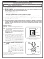
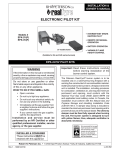
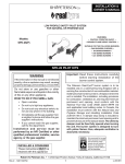
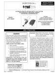
• INTERMITTENT SPARK
IGNITION PILOT
Models:
EPK-2V(P)-TR
EPK-3V(P)-TR
• REMOTE OR MANUAL
OPERATION
• AC POWER OPERATION
2V model shown
• VARIABLE FLAME
HEIGHT CONTROL
(Suitable for G4 and G45 series burners)
EPK-2V/3V-TR PILOT KITS
Important: Read these instructions carefully
before starting installation of the
burner control system.
WARNING
If the information in this manual is not followed
exactly, a fire or explosion may result, causing
property damage, personal injury, or loss of life.
The Peterson Real-Fyre® burner system is to be
installed only in a solid-fuel-burning fireplace with a
working flue constructed of noncombustible material.
Solid fuels shall not be burned in a fireplace where the
unit is installed. The installation, including provisions
for combustion, ventilation air, and required minimum
permanent vent opening, must conform with the
National Fuel Gas Code (ANSI Z223.1/NFPA 54)
and applicable local building codes. In Canada, the
installation must conform with the Natural Gas and
Propane Storage and Handling Installation Code
(CSA-B-149.1). A damper stop clamp is included to
maintain the minimum permanent vent opening and to
prevent full closure of the damper blade. The chimney
damper must be fixed fully opened when burning
the unit. The burner system is designed to burn
with yellow flames; thus, adequate ventilation is
absolutely necessary.
Do not store or use gasoline or other
flammable vapors and liquids in the vicinity
of this or any other appliance.
WHAT TO DO IF YOU SMELL GAS:
• Open a window.
• Do not try to light any appliance.
• Do not touch any electrical switch; do
not use any phone in the building.
• Immediately call the gas supplier from
a neighbor’s phone and follow the gas
supplier’s instructions.
• If you cannot reach the gas supplier,
call the fire department.
Installation and service must be
performed by an NFI Certified or other
qualified professional installer, service
agency, or the gas supplier.
INSTALLER & CONSUMER
These instructions MUST be
retained with this appliance
Robert H. Peterson Co. • 14724 East Proctor Avenue • City of Industry, California 91746
Rev 0 - 1312261320
1
L-A2-376
TABLE OF CONTENTS
GETTING STARTED
IMPORTANT INFORMATION ..................................................................................................................... 3
SPECIFICATIONS......................................................................................................................................... 4
REPLACEMENT PARTS LIST - 2V MODEL.............................................................................................. 5
REPLACEMENT PARTS LIST - 3V MODEL.............................................................................................. 6
INSTALLATION
INSTALLATION............................................................................................................................................ 7
PREPARATION......................................................................................................................................... 7
INSTALL PILOT MOUNTING BRACKET ................................................................................................... 7
INSTALL THE VALVE ............................................................................................................................... 7
INSTALL THE FLAME DIVERTER BRACKET ........................................................................................... 8
INSTALL THE PILOT/IGNITER ASSEMBLY TO THE BURNER .................................................................. 8
CONNECT TO GAS SUPPLY .................................................................................................................... 9
CONNECT TO A POWER SUPPLY .......................................................................................................... 10
INSTALL/REPLACE REMOTE TRANSMITTER BATTERIES ..................................................................... 10
HEAT SHIELD PLACEMENT .................................................................................................................. 10
DECORATIVE MEDIA REPLACEMENT.................................................................................................. 10
USE, CARE, & SERVICE
LIGHTING INSTRUCTIONS ..................................................................................................................... 11
REMOTE LIGHTING .............................................................................................................................. 11
MANUAL LIGHTING .............................................................................................................................. 12
PILOT APPEARANCE ............................................................................................................................ 12
SHUTTING DOWN ................................................................................................................................. 12
REMOTE OPERATING INSTRUCTIONS ................................................................................................ 13
ORIENTATION ....................................................................................................................................... 13
FLAME HEIGHT .................................................................................................................................... 13
TIMER ................................................................................................................................................... 13
TEMPERATURE INDICATOR ( ˚F or ˚C)................................................................................................. 13
TROUBLESHOOTING ............................................................................................................................... 14
SYNCING THE REMOTE ........................................................................................................................ 14
ELECTRONIC PILOT TROUBLESHOOTING ......................................................................................... 15
WARRANTY ............................................................................................................................................... 16
Rev 0 - 1312261320
2
L-A2-376
IMPORTANT INFORMATION
CHECK TO BE SURE THAT THE PROPER FUEL GAS IS BEING USED WITH THIS PILOT KIT.
The installation, including provisions for combustion and ventilation air, must conform with local codes, or in the
absence of local codes, with the National Fuel Gas Code (ANSI Z223.1/NFPA 54).
This component and its individual shutoff valve must be disconnected from the gas-supply piping system when
testing at pressures that exceed 1/2 psig. This is accomplished by closing the gas-supply line valve.
This component must be isolated from the gas-supply piping system by closing its individual manual shutoff
valve during any testing of the gas-supply system at test pressures up to and including 1/2 psig.
A fireplace screen must be in place when the gas burner system is in operation. Unless other provisions for
combustion air are provided, the screen shall have an opening(s) for introduction of combustion air.
WHEN GLASS FIREPLACE ENCLOSURES (DOORS) ARE USED, OPERATE THE BURNER SYSTEM WITH
THE GLASS DOORS FULLY OPEN; BOTH SIDES IF THE FIREPLACE IS A SEE-THROUGH TYPE.
This appliance may be installed in an aftermarket, permanently located, manufactured (mobile) home where not
prohibited by local codes. Installation of appliances designed for manufactured homes or mobile homes must
conform with Manufactured Home Construction and Safety Standard, Title 24 CFR, Part 3280 in the U.S.; or with
CAN/CSA Z240 MH in Canada; or with ANSI/NCSBCS A225.1/NFPA 501A, Manufactured Home Installations
Standard when such as standard is not applicable.
Do not use this appliance if any part has been underwater. Immediately call a qualified service technician to
inspect the appliance and to replace any part of the control system and any gas control that has been underwater.
IT IS CRITICAL THAT THE HEAT SHIELD BE PLACED CORRECTLY OVER THE VALVE
FOR THE UNIT TO OPERATE CORRECTLY.
Rev 0 - 1312261320
3
L-A2-376
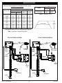
SPECIFICATIONS
Minimum firebox dimensions required for burner system
(with EPK valve attached):
Model
Nat.
L.P.
EPK-2V(P)
120 k
180 k
EPK-3V(P)
200 k
320 k
Min. Firebox Dimensions
Burner size
Center Width *
Depth
Height
EPK-2V
EPK-3V
16/19"
31"
39"
16"
18"
18/20"
32"
40"
16"
18"
24"
36"
44"
16"
18"
30"
42"
50"
16"
18"
36"
48"
56"
16"
18"
42"
54"
62"
16"
18"
48"
60"
68"
16"
18"
54"
66"
74"
16"
18"
60"
72"
80"
16"
18"
BTUs
Table 2 - Maximum BTUs
Depth
Center width
* This required width allows for centering of the log set.
Table 1 - Minimum Firebox Dimensions
EPK-2V WIRING DIAGRAM
EPK-3V WIRING DIAGRAM
Pilot/Igniter
assembly
Ignition
module
pack
Pilot/Igniter
assembly
Ignition
module
pack
Wire
harness
Wire
harness
Shut off
valve
Control
valve
Control
valve
Switch
AC adapter
AC adapter
Switch
Fig. 4-1
Rev 0 - 1312261320
4
L-A2-376
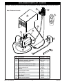
REPLACEMENT PARTS LIST - 2V MODEL
DO NOT REMOVE THE PILOT/IGNITER ASSEMBLY FROM THE VALVE OR IGNITER PACK.
2
1
Note: Photos not to scale
5
9
ON
ON
AUTO
TIMER
HI/LO
OFF
10
8
3
7
4
6
Item Description
Rev 0 - 1312261320
Part No.
Qty.
PAC-11
1
PAC-11P
1
1.
Pilot/igniter assembly (natural)
or
Pilot/igniter assembly (propane)
2.
Pilot mounting bracket kit
PB-51
1
3.
Control valve w/ wire harness (Nat.)
SV-49
1
or
Control valve w/ wire harness (L.P.)
SV-49P
1
4.
Ignition module pack
IMP-5
1
5.
Remote
AT-12V-1
1
6.
Flame diverter bracket
SH-1
1
7.
Power supply
TR-02
1
8.
Main valve wire harness
WH-03
1
9.
Heat shield
HS-41
1
10.
Switch w/ wire harness
SW-22
1
5
L-A2-376
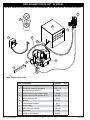
REPLACEMENT PARTS LIST - 3V MODEL
DO NOT REMOVE THE PILOT/IGNITER ASSEMBLY FROM THE VALVE OR IGNITER PACK.
1
5
ON
ON
AUTO
TIMER
HI/LO
OFF
9
2
7
8
10
3
4
6
Note: Photos not to scale
Item Description
Rev 0 - 1312261320
Part No.
Qty.
PAC-11
1
PAC-11P
1
1.
Pilot/igniter assembly (natural)
or
Pilot/igniter assembly (propane)
2.
Pilot mounting bracket kit
PB-51
1
3.
Control valve w/ wire harness (Nat.)
SV-48
1
or
Control valve w/ wire harness (L.P.)
SV-48P
1
4.
Ignition module pack
IMP-5
1
5.
Remote
AT-12V-1
1
6.
Flame diverter bracket
SH-1
1
7.
Power supply
TR-02
1
8.
Main valve wire harness
WH-04
1
9.
Heat shield
HS-42
1
10.
Switch w/ wire harness
SW-22
1
6
L-A2-376
INSTALLATION
This safety pilot system must be installed by a qualified professional service technician. Instructions
must be followed carefully when installing to ensure proper performance and full benefit from the
burner system and safety pilot system.
These instructions must be used as a supplement to the instructions supplied with the R.H. Peterson burner
system. Follow the burner system instructions and make adjustments as appropriate for the addition of a safety
pilot system. Use gas pipe sealing compound that is resistant to all gasses (or Teflon tape) and apply to all
male pipe connections. Make sure that all connections are tight.
The valve system is shipped pre-assembled for easy
installation onto the burner pan. Perform installation with
care ensuring not to damage the pilot assembly, or the
wires that connect the components and heat shield.
Fasten
bracket to
burner pan
Note: Installation is easier when done outside of the
fireplace.
PREPARATION
If the burner that the valve system is to be added to is
already installed; remove all decorative media, set aside to
be reinstalled later, and disconnect the flex connector and
adapter from the burner pan (using the instructions that
came with the original burner).
INSTALL PILOT MOUNTING BRACKET
Fig. 7-1
Install for 2V and
3V valves is the
same. 2V SHOWN.
Attach the valve to the
air mixer/fuel injector by
rotating the burner pan.
The pilot assembly comes with an L-shaped mounting
bracket.Remove the two phillips screws holding the bracket
in place, then use them to fasten the bracket to burner pan
(short side toward the back of the pan) using the pre-drilled
holes in the pan (see Fig. 7-1).
Fuel injector
or air mixer
INSTALL THE VALVE
1. Apply gas pipe sealing compound (or Teflon tape) to the
male end of the fuel injector or air mixer on the burner.
2. Attach the adapter (pre-assembled to valve) to the fuel
injector or air mixer by screwing the pan into the adapter
(Fig. 7-2). Take care not to damage the attached pilot
assembly when rotating the burner pan. Be sure all
connections are tight.
Burner pan
Adapter
Valve
Fig. 7-2
Important: The rear of the valve may need to be angled
slightly upward to allow for the pan to sit flat
against the fireplace floor. Adjust as necessary.
Rev 0 - 1312261320
7
L-A2-376
INSTALLATION (Cont.)
INSTALL THE FLAME DIVERTER BRACKET
For installation on G4/G45 burners only. When properly
installed onto the burner pan, the flame diverter bracket
will promote quicker ignition and protect the safety control
system from overheating.
REAR WALL
1
22-1/2
/2"
BURNER
Burner
PAN
pan
Note: You must first install the flame diverter bracket
before installing the pilot/igniter assembly .
1. Place the flame diverter bracket over the side edge
of the burner pan, near the location the safety control
system pilot bracket will be attached. It should be
placed approximately 2-1/2" from the rear wall of
the burner pan (see Fig. 8-1).
FLAME
Flame
DIVERTER
BRACKET
diverter
bracket
Fig. 8-1
2. Tap the bracket lightly with a hammer to secure it in
place.
Pilot assembly
installed
INSTALL THE PILOT/IGNITER ASSEMBLY TO
THE BURNER
CAUTION: Use only the pilot assembly pre-assembled
with this kit. Never substitute with an existing
pilot.
CAUTION: Do not kink or damage the pilot supply tube,
sparking, and sensor probes. Do not unscrew
the gas line from the valve.
Fasten pilot
assembly to
bracket
(Valve not shown
for clarity)
Fig. 8-2
1. Using the two (2) remaining screws, mount the pilot
assembly onto the bracket (from below) and tighten
until snug (Fig. 8-2). Check to be certain the pilot
hood and probes are situated above the edge of
the pan. Adjust if necessary.
2. The valve is shipped with the pilot supply tube bent in
an ideal manner to prevent damage / unsafe operation,
and to allow for proper heat shield placement. Maintain
this orientation at all times (reference figures on
following page).
WARNING: Keep the pilot/igniter assembly clear at all
times. Never cover any part of the pilot/
igniter assembly.
Rev 0 - 1312261320
8
L-A2-376
INSTALLATION (Cont.)
CONNECT TO GAS SUPPLY
To connect the valve to the gas supply, the flex connector
kit and component parts will be needed, which are included
with the burner system. Refer to the PARTS LIST in the
instructions supplied with the burner to identify the key
parts needed.
Attach the flex
connector to
the elbow on
the valve
(rear view of valve)
1. MAKE SURE THE FIREPLACE GAS SUPPLY IS
TURNED OFF.
2. Locate the gas-supply stub inside the fireplace and
remove the cap, if attached.
CAUTION:
When removing the cap, make sure the stub
does not turn, loosening the connection inside
the wall.
Fig. 9-1 2V models: Attach flex to valve
3. Attach the flex connector to the elbow/adapter on the
control valve (see Fig. 9-1 or Fig. 9-2). Use Teflon
tape or pipe compound. Tighten securely. (Discard
the smaller connector adapter from the connector
kit, as this is not needed.)
4. Place the burner system in the fireplace. Center the
burner in the fireplace.
5. Be sure gas to the fireplace is off. Attach the large
adapter (included with burner flex connector kit) to
the gas-supply stub using a pipe compound resistant
to all gasses. Tighten securely. Then attach the open
end of the flex connector to the large adapter. Tighten
securely.
Attach the flex
connector to the
adapter on the valve
Fig. 9-2 3V models: Attach flex to valve
6. LEAK TEST: Turn on the fireplace gas supply, and test
at all connections for leaks using the appropriate soapy
water solution. If bubbles appear, a leak is present.
Turn off the gas and tighten at all connections. Repeat
until no leaks are present. If a leak persists, turn off
the gas supply and contact the local gas company
or dealer. NEVER USE A FLAME TO CHECK FOR
LEAKS.
7. Follow the instructions supplied with the Peterson
burner system for any additional requirements
regarding specific burner setup and placement.
Rev 0 - 1312261320
9
L-A2-376
INSTALLATION (Cont.)
CONNECT TO A POWER SUPPLY
CAUTION: ENSURE THE UNIT IS CONNECTED TO
THE GAS LINE AND HAS BEEN TESTED
FOR LEAKS BEFORE YOU CONNECT TO
A POWER SUPPLY.
Locate the supplied power supply and connect it to the
ignition module pack, then route it to a GFCI 120VAC
receptacle (not included) as approriate for your setup.
Observe all codes. See Fig. 10-1.
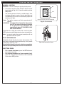
INSTALL/REPLACE REMOTE TRANSMITTER
BATTERIES
CAUTION: ENSURE THE UNIT IS CONNECTED TO
THE GAS LINE AND HAS BEEN TESTED
FOR LEAKS BEFORE YOU INSERT
BATTERIES.
The remote transmitter requires 3 "AAA" batteries to
operate. Locate the transmitter, remove the lid (found
on rear), and properly insert new batteries as marked.
Re-secure the lid. See Fig. 10-2.
To GFCI 120VAC
receptacle
Fig. 10-1 Connect cord to module / power supply
Remove
lid for
battery
access
HEAT SHIELD PLACEMENT
Cover the valve with the heat shield as shown in Fig. 10-3
or Fig. 10-4.
It is critical that the heat shield be placed correctly
over the valve for the unit to operate properly. The
switch wire connecting the heat shield to the ignition
module pack is to be routed along the interior right
side of the heat shield. Keep all wires inside of the
heat shield and/or away from the flame. Keep the area
above the heat shield clear of decorative media or
any other object.
Important: Ensure the pilot supply tube does not
interfere with heat shield placement. For
2V models, the tube will come out of the
rear and coil back to the pilot. For 3V
models, the tube will come out of the left
side of the heatshield and coil to the pilot.
DECORATIVE MEDIA REPLACEMENT
Refer to the burner instructions for proper replacement
of decorative media.
Fig. 10-2 Install/replace transmitter batteries
Valve
heat shield
in place
Heat
shield
Burner pan
Fig. 10-3 2V models: Place heat shield
Valve
heat shield
in place
Heat
shield
Burner pan
Fig. 10-4 3V models: Place heat shield
Rev 0 - 1312261320
10
L-A2-376
LIGHTING INSTRUCTIONS
FOR YOUR SAFETY READ BEFORE LIGHTING
WARNING: If you do not follow these instructions exactly, a fire or explosion may result causing property
damage, personal injury or loss of life.
A. This appliance is equipped with an ignition device that automatically lights the pilot. DO NOT attempt to
light the pilot by hand.
B. BEFORE OPERATING, smell all around the appliance area for gas. Be sure to smell next to the floor
because some gas is heavier than air and will settle on the floor.
WHAT TO DO IF YOU SMELL GAS
• Do not light any appliance.
• Do not touch any electric switch; do not use any phone in your building.
• Immediately call your gas supplier from a neighbor's phone. Follow the gas supplier's instructions.
If you cannot reach your gas supplier, call the fire department.
C. Use only the supplied switch or the control/remote system components to light the pilot. This valve will not
operate if the pilot is not lit and stable.
D. Do not use this appliance if any part has been under water. Immediately call a qualified service technician
to inspect the appliance and to replace any part of the control system and any gas control which has been
under water. Attempted operation may result in fire or explosion resulting in property damage, personal
injury or loss of life.
REMOTE LIGHTING
CAUTION: DO NOT attempt to light the pilot by hand.
Note: Step 1 may not be required if previously done during
an earlier lighting.
ON
II O I
1. Locate the 3-position switch found on the front of the
heatshield (see Fig. 11-1). Press the switch down to
the REMOTE position.
2. Locate the remote transmitter and press the ON key
(see Fig. 11-2). The ignition sequence will begin.
The remote receiver will emit an audible "beep"; then
the igniter will begin to spark. After the pilot lights and
is established, the valve will automatically open and
the burner will light. Adjust to the desired setting(s) with
the remote transmitter. See the REMOTE OPERATING
INSTRUCTIONS section for details.
Note: The ignition sequence will take approximately 5
seconds.
WARNING: If the pilot fails to light within 10 seconds,
press the OFF button on the remote
transmitter or move the switch to the
center OFF position to turn OFF the
system. Allow five (5) minutes for any gas
in the unit to dissipate, then repeat step
2 above. IF YOU SMELL GAS, SEE STEP
B ABOVE.
If the pilot fails to light after several tries, turn all control/
remote system components to OFF and contact a qualified
professional service technician.
11
OFF
REMOTE
(switch is located on front of heatshield)
Fig. 11-1 Switch detail
(Display
screen)
ON/UP
key
ON
ON
Timer
key
AUTO
TIMER
HI/LO
HI/LO key
OFF
OFF/DOWN
key
Fig. 11-2 Remote transmitter detail
LIGHTING INSTRUCTIONS (cont.)
MANUAL LIGHTING
CAUTION: DO NOT attempt to light the pilot by hand.
The remote receiver will emit an audible "beep"; then
the igniter will begin to spark. After the pilot lights and
is established, the valve will automatically open and
the burner will light.
Note: The ignition sequence will take approximately 5
seconds.
II O I
1. Locate the 3-position switch found on the front of the
heatshield (see Fig. 12-1). Press the switch up to the
ON position.
ON
OFF
REMOTE
(switch is located on front of heatshield)
Fig. 12-1 Switch detail
WARNING: If the pilot fails to light within 10 seconds,
turn OFF the system. Allow five (5) minutes
for any gas in the unit to dissipate, then
repeat step 2 above. IF YOU SMELL GAS,
SEE STEP B ABOVE.
If the pilot fails to light after several tries, turn the system
OFF and contact a qualified professional service technician.
Note: In manual mode, the remote transmitter will not
operate the burner system.
PILOT APPEARANCE
Periodically check the pilot for proper flame pattern. The
pilot flame should encircle the generator tip, and is preset
at the factory (see Fig. 12-2).
If the pilot flame burns incorrectly; shut down completely
and contact a qualified professional service technician.
SHUTTING DOWN
• For a remote shut down, press the OFF button on
the remote transmitter.
• For a manual shutdown (or if your remote is lost),
press the switch found on the front of the heatshield
to the center OFF position.
12
Fig. 12-2 Proper pilot flame
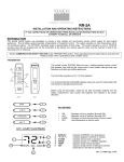
REMOTE OPERATING INSTRUCTIONS
ORIENTATION
Prior to remote transmitter use, light the appliance per the
REMOTE LIGHTING section. The remote will only operate
the burner system in remote mode. Familiarize yourself with
the transmitter keys and display, as illustrated in Fig. 13-1
and Fig. 13-2.
(Display
screen)
ON/UP
key
ON
ON
Timer
key
Identify the four transmitter keys:
AUTO
TIMER
HI/LO
HI/LO key
OFF
• ON/OFF KEYS: These keys turn the system ON or OFF.
OFF/DOWN
key
• HI/LO KEY: This key, when the system is on, is used to
set the desired flame height via the Flame Height mode.
• TIMER KEY: This key, when the system is on, is used to
set the desired time via the Timer mode.
• UP/DOWN KEYS: In Flame Height or Timer mode, the
ON/OFF keys become UP/DOWN keys to increase or
decrease the Flame Height or Timer amount.
The display will show all active icons on the screen.
Fig. 13-1 Remote transmitter detail
ROOM
Flame Height
/ Timer
detail
FLAME HEIGHT
Five flame height levels are available. Press the HI/LO key to
enter the Flame Height mode. A number 1 - 5 will be displayed
at the bottom of the screen. Pressing the Up/Down keys once
will increase/decrease the flame height by 1 of 5 increments.
See Fig. 13-3.
88°F
Transmission
TIMER
To turn off the timer mode press the OFF key. This will turn
off the unit.
Flame icon
indicates
system is in
operation
Fig. 13-2 Remote display detail
ROOM
80°F
TIMER
In Timer Mode, the unit will remain functioning until the set
amount of time has expired. Press the Timer key to enter the
Timer mode. Pressing the Up/Down keys once in this mode will
increase/decrease the set time in increments of 10 minutes.
See Fig. 13-4.
20
Room
temperature
Set desired
flame level
1-5
TIMER
SET
73°F
Fig. 13-3 Flame height detail
ROOM
80°F
TEMPERATURE INDICATOR ( ˚F or ˚C)
Set
desired
time
The temperature can be displayed in °F or °C. When you first
install the batteries, the temp indicator at the top of the screen
will be flashing. Use the Up/Down keys to switch between °F
or °C.
TIMER
SET
20°e
Fig. 13-4 Timer detail
13
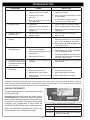
TROUBLESHOOTING
PROBLEM
1. Pilot will not light
CAUSE
SOLUTION
a. Obstruction in pilot gas supply or
pilot gas-supply line is kinked
a. Clear out obstruction. Replace pilot gassupply line if kinked
b. Inadequate gas supply
b. Have gas pressure checked by installer
or gas supplier
c. Air in line
d. Gas is shut off on control valve
(3V models only)
2. No spark at pilot
c. Air should clear; attempt to relight
d. Turn on valve (3V models only)
a. Loose wires
a. Check all wires are securely in place
b. Appliance not receiving power
b. Check remote batteries / power supply
c. Fa u l t y sw i t c h o r r e m o t e ( i f
equipped)
c. Replace the switch or remote system as
appropriate
3. Pilot lights, but main
burner will not
a. Loose or broken connector wires
a. Check and replace if necessary
b. Defective valve
b. Replace valve
4. Log set not burning
properly
a. Low flame/uneven flame
a. Check for low gas pressure; should have
operating pressures of 7" w.c. for natural
gas, 11" w.c. for propane at manifold
b. Burner should be filled completely with
sand or vermiculite
5. Log set shuts down
during operation
a. Glass doors closed, causing
excessive heat buildup
b. Pilot electrode not properly set to
pilot location
a. Open glass doors
b. See INSTALL THE PILOT ASSEMBLY
TO THE BURNER section
c. Heat shield not in place
c. Place heat shield over valve. Be sure the
solid black face of the shield is between
the valve and the burner
6. Intermittent ignitor spark
during use (main burner
has been burning for well
over a minute).
a. Embers or sand covering pilot
assembly
a. Clear all foreign material from around the
pilot assembly
7. Remote control not
functioning
a. Appliance not receiving power
a. Check remote batteries / power supply
b. No gas flow to the valve
b. Check gas supply to valve
c. Remote too far from receiver
c. Move remote closer to receiver
d. Spark ignition interfering with
remote signal
d. Move remote closer to receiver
Periodically inspect the pilot assembly and valve controls and maintain them free of obstruction or debris. If the pilot
flame is not blue with possibly yellow tips and does not impinge on the electrodes or if the pilot does not stay lit, contact
a qualified professional service technician to service the pilot system.
SYNCING THE REMOTE
SYNC button
The ignition module pack has a sync button that is located
next to the LED light.
LED light
Move the 3-position switch (on the heat shield) down to
the REMOTE position. Then press upward on the sync
button and hold. One beep will be heard. While continuing
to hold, press and hold the "ON" button on the remote
transmitter, until a double beep is heard. Follow the
LIGHTING INSTRUCTIONS to test remote funcionality.
Refer to the TROUBLE CODES table for a guide if the
ignition module pack is flashing the red lights.
14
RED LED TROUBLE CODES
1 Flash
Nat/LP selector not in correct position
2 Flashes
HI voltage coil failure, no spark
3 Flashes
Shorted sensor, no gas flow, no ignition
of pilot in 60 seconds
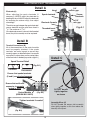
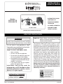
ELECTRONIC PILOT TROUBLESHOOTING
Detail A
Electrode (A)
When adjusting the spark electrode (if
necessary); NEVER adjust the electrode by
bending the wire. ALWAYS adjust the electrode
by loosening the retainer nut(s), then adjust
accordingly.
The minimum gap between the spark electrode/
sensor electrode and the pilot flame hood is
1/8". The maximum is 5/32".
Hood
Spark electrode
Electrode Ceramic
Threaded barrel
1/8"
min. gap
Sensor
electrode
1/8"
min. gap
Fig. A-1
If the electrode ceramic is loose in the threaded
barrel; the pilot assembly must be replaced.
Retainer nuts
Detail B
Terminal Connections (B)
All of the connections on the control module
must be properly attached. If the spade
terminals are loose; inspect to ensure they
correctly appear as detailed below. Use needle
nose pliers to clamp down on the center/sides
of the terminals if needed (to provide a tight fit.)
Detail C
(Fig. C-1)
Spade Terminal Detail
(Fig. B-1)
CORRECT
INCORRECT
Ensure that spade terminals
(S and I) are attached securely
Ensure that multi-wire
connector is properly
locked in place
Control Module
(DESIGN MAY VARY)
DO NOT bundle
tightly together
as shown
(Fig. B-2)
Tighten terminals if needed
Assembly Wires (C)
DO NOT bundle the excess pilot assembly
wires tightly together as this can reduce the
intensity of the spark.
(Fig. B-3)
15
WARRANTY
PETERSON VENTED DECORATIVE GAS APPLIANCE
LIMITED WARRANTY
Robert H. Peterson Co. ("RHP") warrants your Real Fyre® vented decorative gas appliance to be free from defects in material and
workmanship.
Peterson vented ceramic refractory gas logs are warranted for as long as you own them (lifetime).
Peterson vented burner assemblies are WARRANTED for TEN (10) YEARS. Peterson vented outdoor stainless-steel burner
assemblies are warranted for FIVE (5) YEARS.
Peterson glass, gems, nuggets, and fiber-ceramic blend gas logs are warranted for FIVE (5) YEARS.
SPK-26 controls are warranted for THREE (3) YEARS.
APK-17 controls (including -17 valve) are warranted for TWO (2) YEARS.
All other Peterson valves, pilots, and controls are warranted for ONE (1) YEAR (excluding batteries).
A COPY OF YOUR SALES SLIP FOR PROOF OF PURCHASE IS REQUIRED
This warranty applies to the original purchaser for products which are installed in the United States or Canada and which are operated and maintained
as intended for single family residential usage. This warranty is valid only with proof of purchase, shall commence on the date of purchase, and shall
terminate (both as to original and any replacement products) on the anniversary date of the original purchase of the product stated on the above schedules.
This warranty covers defects in material and workmanship. This warranty does not cover parts which become defective as a result of negligence, misuse,
use not in compliance with the Owner’s Manual/Installation Instructions, accidental damage, improper handling, improper storage, improper installation,
lack of required routine maintenance (as specified in the Owner’s Manual/Installation Instructions), electrical damage, local gas impurities or failure to
protect against combustibles. Product must be installed (and gas must be connected) as specified in the Owner’s Manual/Installation Instructions by
a qualified professional installer. Modifications to products which are not specifically authorized will void this warranty. Accessories, parts, valves,
remotes, etc. when used must be Peterson products or this warranty is void. Warrantied items will be repaired or replaced at Peterson’s sole discretion.
This warranty does not apply to rust, corrosion, oxidation, or discoloration unless the affected part becomes inoperable.
This warranty does not cover labor or labor related charges, except as provided by separate specific written programs from the Peterson Co. All repair
work must be performed by a qualified professional service person and requires prior approval of Peterson.
Peterson may require the defective product or part to be returned to the factory to determine the cause of failure. Peterson will pay freight charges if
the product or part is determined to be defective. This warranty does not cover breakage in shipment from our (Independent) distributor to its customer
if the damage is determined to have occurred during that shipment.
This warranty specifically excludes liability for indirect, incidental, or consequential damages. Some states and provinces do not allow the exclusion
or limitation of incidental or consequential damages, so the above exclusion may not apply to you. This warranty gives you specified legal rights, and
you may have other rights that vary from state to state or province.
For additional information regarding this warranty, or to place a warranty claim, contact the R. H. Peterson dealer where the product was purchased.
TO REGISTER YOUR PRODUCT ONLINE GO TO: WWW.RHPETERSON.COM,
AND CLICK ON PRODUCT REGISTRATION. THANK YOU FOR YOUR PURCHASE.
Quality Check
Date:_________________
Leak Test:
________________ Burn Test: _________________ Gas Type:
Inspector:
________________
16
Nat. / L.P.