1
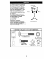
Owner's Manual
JCRIIFTSMIIWI
FRONT TINE TILLER
WITH REVERSE
6.0 HP
26 Inch Tine Width
Model No.
917.292492
@
This product has a low emission engine which operates
differently from previously built engines, Before you start
the engine, read and understand this Owner's Manual.
CAUTION:
Read and follow all Safety
Rules and Instructions before
operating this equipment.
Sears, Roebuck and Co., Hoffman Estates, II 60179 U.S.A.
Visit our Craftsman website:www.sears.com/craftsman
]
Maintenance
Schedule ...................... 11
Service and Adjustments .................... 13
Storage ...............................................
16
Troubleshooting
.................................
17
Illustrated Parts List ............................ 38
Sears Service ...................... Back Cover
Warranty ...............................................
2
Safety Rules .........................................
2
Product Specifications .......................... 4
Assembly ..............................................
6
Operation ..............................................
7
Maintenance .......................................
11
LIMITED TWO YEAR WARRANTY
ON CRAFTSMAN
TILLER
For two (2) years from date of purchase, when this Craftsman Tiller is maintained,
lubricated, and tuned up according to the operating and maintenance instructions in
the owner's manual, Sears will repair free of charge any defect in material or workmanship.
This Warranty does not cover:
• Expendable items which become worn during normal use, such as tines, spark
plugs, air cleaners and belts.
• Repairs necessary because of operator abuse or negligence, including bent
crankshafts and the failure to maintain the equipment according to the instructions
contained in the owner's manual.
• If this Craftsman Tiller is used for commercial or rental purposes, this Warranty
applies for only thirty (30) days from the date of purchase.
Warranty service is available by returning the craftsman power mower to the nearest
sears service center/department
in the united states. This warranty applies only while
this product is in use in the united states.
This Warranty gives you specific legal rights, and you may also have other rights which
vary from state to state.
SEARS,
ROEBUCK AND CO., D/817WA,
HOFFMAN
ESTATES, IL 60179
IMPORTANT: This cutting machine is capable of amputating hands and feet and
throwing objects. Failure to observe the following safety instructions could result in
serious injury or death,
TRAINING
• Disengage all clutches and shift into
neutral before starting the engine
(motor).
• Do not operate the equipment without
wearing adequate outer garments.
Wear footwear that will improve footing
on slippery surfaces.
• Handle fuel with care; it is highly
flammable.
• Use an approved fuel container.
• Never add fuel to a running engine or
hot engine.
• Fill fuel tank outdoors with extreme
care. Never fill fuel tank indoors.
• Replace gasoline cap securely and
clean up spilled fuel before restarting.
• Read the Owner's Manual carefully. Be
thoroughly familiar with the controls
and the proper use of the equipment.
Know how to stop the unit and disengage the controls quickly.
• Never allow children to operate the
equipment. Never allow adults to
operate the equipment without proper
instruction.
• Keep the area of operation clear of all
persons, particularly small children,
and pets.
PREPARATION
• Thoroughly inspect the area where the
equipment is to be used and remove all
foreign objects.
2
• Use extension cords and receptacles
as specified by the manufacturer for all
units with electric drive motors or
electric starting motors.
• Never attempt to make any adjustments
while the engine (motor) is running
(except where specifically recommended by manufacturer).
• Do not overload the machine capacity
by attempting to till too deep at too fast
a rate.
• Never operate the machine at high
speeds on slippery surfaces. Look
behind and use care when backing.
• Never allow bystanders near the unit.
• Use only attachments and accessories
approved by the manufacturer of the
tiller.
• Never operate the tiller without good
visibility or light.
• Be careful when tilling in hard ground.
The tines may catch in the ground and
propel the tiller forward. If this occurs,
let go of the handlebars and do not
restrain the machine.
OPERATION
• Do not put hands or feet near or under
rotating parts.
• Exercise extreme caution when
operating on or crossing gravel drives,
walks, or roads. Stay alert for hidden
hazards or traffic. Do not carry passengers.
• After striking a foreign object, stop the
engine (motor), remove the wire from
the spark plug, thoroughly inspect the
tiller for any damage, and repair the
damage before restarting and operating the tiller.
• Exercise caution to avoid slipping or
falling.
• If the unit should start to vibrate
abnormally, stop the engine (motor)
and check immediately for the cause.
Vibration is generally a warning of
trouble.
• Stop the engine (motor) when leaving
the operating position.
• Take all possible precautions when
leaving the machine unattended.
Disengage the tines, shift into neutral,
and stop the engine.
• Before cleaning, repairing, or inspecting, shut off the engine and make
certain all moving parts have stopped.
Disconnect the spark plug wire, and
keep the wire away from the plug to
prevent accidental starting. Disconnect
the cord on electric motors.
• Do not run the engine indoors; exhaust
fumes are dangerous.
• Never operate the tiller without proper
guards, plates, or other safety protective devices in place.
• Keep children and pets away.
MAINTENANCE
AND STORAGE
• Keep machine, attachments, and
accessories in safe working condition.
• Check shear pins, engine mounting
bolts, and other bolts at frequent
intervals for proper tightness to be sure
the equipment is in safe working
condition.
• Never store the machine with fuel in the
fuel tank inside a building where
ignition sources are present, such as
hot water and space heaters, clothes
dryers, and the like. Allow the engine to
cool before storing in any enclosure.
• Always refer to the operator's guide
instructions for important details if the
tiller is to be stored for an extended
period.
_kLook for this symbol to point out
important safety precautions. It means
CAUTION!!!
BECOMEALERT!!!
YOUR
SAFETY IS INVOLVED.
ACAUTION:
Always disconnect spark
plug wire and place wire where it cannot
contact spark plug in order to prevent
accidental starting when setting up,
transporting, adjusting or making repairs.
AWARNING:
Engine exhaust, some of its
constituents, and certain vehicle components contain or emit chemicals known to
the State of California to cause cancer
and birth defects or other reproductive
harm.
3
PRODUCT
CUSTOMER
SPECIFICATIONS
Gasoline
Capacity:
3 Quarts
Unleaded
Regular
Oil (API-SF-SJ):
SAE 30
(Above 32°F)
SAE 5W-30
(Below 32°F)
(Capacity: 20 oz.)
Spark Plug :
(Gap: .030")
RESPONSIBILITIES
• Read and observe the safety rules.
• Follow a regular schedule in maintaining, caring for and using your tiller.
• Follow the instructions under the
"Customer Responsibilities" and
"Storage" sections of this Owner's
Manual.
_L, WARNING: This unit is equipped with
an internal combustion engine and
should not be used on or near any
unimproved forest-covered,
brushcovered or grass covered land unless the
engine's exhaust system is equipped with
a spark arrester meeting applicable local
or state laws (if any). If a spark arrester is
used, it should be maintained in effective
working order by the operator.
In the state of California the above is
required by law (Section 4442 of the
California Public Resources Code).
Other states may have similar laws.
Federal laws apply on federal lands. A
spark arrester for the muffler is available
through your nearest Sears service
center (See REPAIR PARTS section of
this manual).
Champion
RC12YC
CONGRATULATIONS
on your purchase
of a Sears Tiller. It has been designed,
engineered and manufactured to give
you the best possible dependability and
performance.
Should you experience any problems you
cannot easily remedy, please contact a
Sears or other qualified Service Center.
We have competent, well-trained technicians and the proper tools to service or
repair this unit.
Please read and retain this manual. The
instructions will enable you to assemble
and maintain your tiller properly. Always
observe the "SAFETY RULES".
Your new tiller has been assembled at the
factory with exception of those parts left
unassernbled for shipping purposes. To
ensure safe and proper operation of your
tiller all parts and hardware you assemble must be tightened securely. Use
the correct tools as necessary to insure
proper tightness.
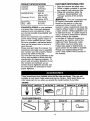
These accessories
were available
when the tiller was purchased.
They are also
available at most Sears Retail outlets and Service Centers.
Most Sears Stores can
order repair parts for you when you provide the model
number
of your tiller.
ENGINE
GAS CAN
TILLER
MAINTENANCE
BELT
TINES
SHEAR PIN
O
4
HAIRPIN CLIP
Your new tiller has been assembled at the
factory with the exception of those parts left
unassembled for shipping purposes. To
ensure safe and proper operation of your
tiller all parts and hardware you assemble
must be tightened securely. Use the correct
tools as necessary to insure proper
tightness.
TOOLS REQUIRED
Front
Left
FOR ASSEMBLY
A socket wrench set will make assembly
easier. Standard wrench sizes are listed.
(1) Utility knife
(t) Screwdriver
(1) Pair of pliers
(2) 1/2" wrenches
OPERATOR'S POSITION
_
When right or left hand is mentioned in this
manual, it means when you are in the
operating position (standing behind tiller
handles).
CONTENTS
Right
Operator's
OF HARDWARE
Position
PACK
O
(2) Carriage Bolts
5/16-18 UNC x 2-1/2
(2) Flange
Locknuts
5/16-18
UNC
(1) Manual
Q
5/16-18
x 1-1/4
(1) Bottle
Engine Oil
5
(1) Lock
Washer
5/16
(1) Hex Nut
5/16-18
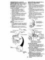
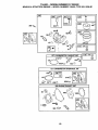
UNPACK
HANDLE
CARTON
& INSTALL
_CAUTION:
Be careful of exposed
staples when handling or disposing of
cartoning material.
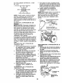
IMPORTANT: When unpacking and
assembling tiller, be careful not to stretch
or kink cable(s).
1. Cut cable ties securing handle
column.
2. Route cable(s) as shown and slide
handle column onto handle mount.
3. Remove all packing from carton.
4. Secure handle column using two (2)
carriage bolts and two (2) flange
Iocknuts. Tighten securely.
5. Cut away carton.
6. Route tine control cable(s) through
plastic cable clip on handle mount.
NOTE: Cables must not touch the muffler.
7. Cut cable ties securing tiller to skid.
Remove tiller from skid by pulling
backwards.
8. Remove screw securing depth stake
to skid and discard the screw.
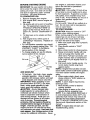
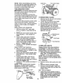
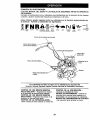
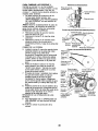
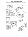
3. Raise and position depth stake
support to align holes in support with
holes "B" and "C" in engine brackets.
4. Install into holes "B" and "C" the
hardware removed earlier and one (1)
each the same hardware from parts
bag. Tighten both bolts securely.
5. Tighten nut "A"
6. Assemble depth stake between depth
stake supports with clevis pin and
hairpin clip.
7. Depth stake must move freely. If it
does not, loosen support bolt.
Nut "A"
HexBolt,
_ _"_"_
Lock Washer-_
/ I/
_Depth
andHexNut
Stake
Support
_
Engine Bracket Halves
\
Depth
Stake
Tine Control
Handle Mount
Tine
Support
Bolt
Cables
. Hairpin Clip
and Clevis Pin
Column
Stake Spring
Holes "B" and "C"
Hex Bolts, Lock Washers,
and hex Nuts
HANDLE HEIGHT
• Handle height may be adjusted to
better suit operator. (See "HANDLE
HEIGHT" in the Service and Adjustments section of this manual).
TILLING WIDTH
Carriage
Bolts
Flange
Locknuts
INSTALL DEPTH STAKE ASSEMBLY
Loosen nut "A".
2. Remove hex nut, Iockwasher and bolt
securing depth stake support to
engine brackets. Save the hardware
for reassembly.
• Tilling width may be adjusted to better
handle your tilling conditions (See
'q-INE ARRANGEMENT"
in the Service
and Adjustments section of this
manual).
.
TINE OPERATION
• Check tine operation before first use.(See "TINE OPERATION CHECK" in
the Service and Adjustments section of
6
this manual).
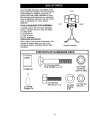
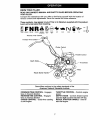
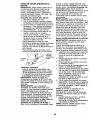
KNOW YOUR TILLER
READ THIS OWNER'S MANUAL AND SAFETY RULES BEFORE OPERATING
YOUR TILLER.
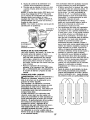
Compare the illustrations with your tiller to familiarize yourself with the location of
various controls and adjustments. Save this manual for future reference.
These symbols ,may appear on yourTiller
Learn and understand their meaning,
33LLING
FORWARD
NEUTRAL
RI_'VERSIE
CAU13ON
WARNING
OR
or in literature supplied with the product.
SLOW
ON
CHOKE
FUEL
OFF
Reverse Tine Control
Forward Tine
Choke Control
Control
Depth Stake
Tines
Recoil Starter
O
Sears tillers conform to the safety standards of the
American National Standards Institute.
FORWARD TINE CONTROL - Engages
tines in forward direction.
REVERSE TINE CONTROL - Engages
tines in reverse direction.
CHOKE CONTROL - Used when starting
a cold engine.
THROTTLE CONTROL - Controls engine
speed.
DEPTH STAKE - Controls forward speed
and the depth at which the tiller will dig.
RECOIL STARTER HANDLE - Used to
start the engine.
7
The operation of any tiller can result in foreign objects
which can result in severe eye damage. Always wear
shields before starting your tiller and while tilling. We
safety glasses or a wide vision safety mask worn over
HOWTO
USEYOURTILLER
The depth stake should always be below
the wheels for digging. It serves as a
brake to slow the filler's forward motion to
enable the tines to penetrate the ground.
Also, the more the depth stake is lowered
into the ground the deeper the tines will
dig.
Know how to operate all controls before
adding fuel and oil or attempting to start
engine.
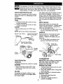
STOPPING
TINES
1. Release
forward
2. Release
reverse
ENGINE
forward tine control to stop
movement.
reverse tine control to stop
movement.
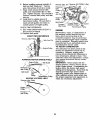
DEPTH STAKE
Adjust depth stake by removing the
hairpin clip and clevis pin. Change depth
stake to desired position. Replace the
clevis pin and hairpin clip.
• For normal tilling, set depth stake at the
second or third hole from the top.
• Move throttle control to "STOP" position.
NOTE: Never use choke to stop engine.
Reverse Tine Control
thrown into the eyes,
safety glasses or eye
recommend standard
spectacles.
WHEELS
Forward Tine Control
"OFF (UP) Position
Adjust wheels by removing the hairpin
clip and clevis pin. Change wheel
position. Replace the hairpin clip and
clevis pin.
• For normal tilling, set wheels at the
second or third hole from the top.
Forward Tine Control
"ON" (DOWN) Position
_"_._
Hairpin Clip
_/_
Throttle
Control
clevis Pin
Wheel _
Chokl
Depth Stake
TOTRANSPORT
TINE OPERATION
_I_CAUTION: Before lifting or transporting,
allow tiller engine and muffler to cool.
Disconnect spark plug wire. Drain
gasoline from fuel tank.
AROUND THE YARD
FORWARD
• Squeeze forward tine control to handle.
REVERSE
• With forward tine control "OFF" (up)
position, pull back and hold reverse
tine control.
1. Tip depth stake forward until it is held
by the stake spring.
2. Push tiller handles down, raising tines
off the ground.
3. Push or pull tiller to desired location.
AROUND TOWN
TILLING
The speed and depth of tilling is regulated by the position of the depth stake
and wheel height.
8
1. Disconnect spark plug wire.
2. Drain fuel tank.
3. Transport in upright position to
prevent oil leakage.
BEFORE STARTING ENGINE
IMPORTANT:Be very careful not to allow
dirt to enter the engine when checking or
adding oil or fuel. Use clean oil and fuel
use engine or carburetor cleaner products in the fuel tank or permanent
damage may occur.
_kCAUTION"
Fill to within 1/2 inch of top
of fuel tank to prevent spills and to allow
for fuel expansion. If gasoline is accidentally spilled, move machine away from
area of spill. Avoid creating any source of
ignition until gasoline vapors have
disappeared.
Do not overfill. Wipe off any spilled oil or
fuel. Do not store, spill or use gasoline
near an open flame.
TO START ENGINE
and store in approved, clean, covered
containers, use clean fill funnels.
FILL ENGINE WITH OIL
• 1. Remove hangtag from engine.
2. With engine level, remove engine oil
filler plug.
3. Fill engine with oil to point of overflowing. For approximate capacity see
"PRODUCT SPECIFICATIONS"
on
page 4 of this manual. All oil must
meet A.P.I. Service Classification SFSJ.
4. Tilt tiller back on its wheels and then
re-level.
5. With engine level, refill to point of
overflowing if necessary. Replace oil
filler plug.
• For cold weather operation you should
change oil for easier starting (See "OIL
VISCOSITY CHART" in the Maintenance section of this manual).
• To change engine oil, see the Maintenance section of this manual.
• I,CAUTION: Keep tine control in "OFF"
position when starting engine•
When starting engine for the first time or if
engine has run out of fuel, it will take
extra pulls of the recoil starter to move
fuel from the tank to the engine.
1. Make sure spark plug wire is properly
connected.
2. Place throttle control in "FAST"
position.
3. Move choke control to choke position.
4. Grasp recoil starter handle with one
hand and grasp tiller handle with
other hand. Pull rope out slowly until
engine reaches start of compression
cycle (rope will pull slightly harder at
this point).
5. Pull recoil starter handle quickly. Do
not let starter handle snap back
against starter.
NOTE: If engine fires but does not start,
move choke control to half choke position.
Pull recoil starter handle until engine
starts.
6. When engine starts, slowly move
choke control to "RUN" position as
engine warms up.
NOTE; A warm engine requires less
choking to start.
7. Move throttle control to desired
running position.
8. Allow engine to warm up for a few
minutes before engaging tines.
NOTE: If at a high altitude (3000 feet) or
in cold temperatures (below 32°F), the
carburetor fuel mixture may need to be
adjusted for best engine performance.
See 'q'O ADJUST CARBURETOR"
in the
Service and Adjustments section of this
manual.
NOTE: If engine does not start, see
troubleshooting
points.
Oil
Oil Filler
Plug
ADD GASOLINE
• Fill fuel tank. Use fresh, clean, regular
unleaded gasoline. (Use of leaded
gasoline will increase carbon and lead
oxide deposits and reduce valve life.)
IMPORTANT; When operating in temperatures below 32°F(0°C), use fresh,
clean, winter grade gasoline to help
insure good cold weather starting.
_I,CAUTION: Alcohol blended fuels
(called gasohol or using ethanol or
methanol) can attract moisture which
leads to separation and formation of
acids during storage. Acidic gas can
damage the fuel system of an engine
while in storage. To avoid engine
problems, the fuel system should be
emptied before storage of 30 days or
longer. Drain the gas tank, start the
engine and let it run until the fuel lines
and carburetor are empty. Use fresh fuel
next season, See Storage section of this
manual for additional information. Never
9
excessive bounce and difficult handling
of your tiller. Hard soil should be
moistened before tilling; however,
extremely wet soil will "ball-up" or
clump during tilling. Wait until the soil is
less wet in order to achieve the best
results. When tilling in the fall, remove
vines and long grass to prevent them
from wrapping around the fine shaft
and slowing your tilling operation.
You will find tilling much easier if you
leave a row untilled between passes.
Then go back between tilled rows.
There are two reasons for doing this.
First, wide turns are much easier to
negotiate than about-faces. Second,
the tiller won't be pulling itself, and
you, toward the row next to it.
Set depth stake and wheel height for
shallow tilling when working extremely
hard soil or sod. Then work across the
first cuts at normal de )th.
Plug
Throttle
Choke
Control
Recoil
BREAKING
INYOURTILLER
Break-in your belt(s), pulleys and tine
control before you actually begin tilling.
• Start engine, tip tines off ground by
pressing handles down and engage
tine control to start tine rotation. Allow
tines to rotate for five minutes.
• Check tine operation and adjust if
necessary. See "TINE OPERATION
CHECK" in the Service and Adjustments section of this manual.
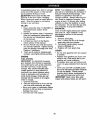
TILLING
HINTS
_i_CAUTION: Until you are accustomed to
handling your tiller, start actual field use
with throttle in slow position (mid-way
between "FAST" and "IDLE").
To help tiller move forward, lift up the
handles slightly (thus lifting depth stake
out of ground). To slow down the tiller,
press down on handles.
If you are straining or tiller is shaking, the
wheels and depth stake are not set
properly in the soil being tilled. The
proper setting of the wheels and depth
stake is through trial and error and
depends upon the soil condition.
(The
harder or wetter the ground, the slower
the engine and tine speed needed. Under
these poor conditions, at fast speed the
tiller will run and jump over the ground).
A properly adjusted tiller will dig with little
effort from the operator.
• Tilling is digging into, turning over, and
breaking up packed soil before
planting. Loose, unpacked soil helps
root growth. Best tilling depth is 4" to
6". A tiller will also clear the soil of
unwanted vegetation. The decomposition of this vegetable matter enriches
the soil. Depending on the climate
(rainfall and wind), it may be advisable
to till the soil at the end of the growing
season to further condition the soil.
• Soil conditions are important for proper
tilling. Tines will not readily penetrate
dry, hard soil which may contribute to
J//
//'//
CULTIVATING
Cultivating is destroying the weeds
between rows to prevent them from
robbing nourishment and moisture from
the plants. At the same time, breaking up
the upper layer of soil crust will help
retain moisture in the soil. Best digging
depth is 1" to 3".
• You will probably not need to use the
depth stake. Begin by tipping the depth
stake forward until it is held by the
stake spring.
• Cultivate up and down the rows at a
speed which will allow tines to uproot
weeds and leave the ground in rough.
condition, promoting no further growth
of weeds and grass.
© ©10 © ©
o olo io o
O ©10 O O
O
10
0 0
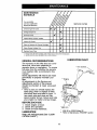
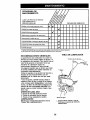
MAINTENANCE
SCHEDULE
FILL IN DATES
AS YOU COMPLETE
REGULAR SERVICE
Check
Change
Engine
Oil Level
Engine
SERVICE DATES
I
V'
ik/
Oil
I_1,_
-
Oil Pivot Points
I/
v'
Inspect Spark Arrester / Muffler
Inspect
v'
Air Screen
Clean or Replace
Air Cleaner
Cartridge
Clean Engine Cylinder Fins
Replace
l/
i/
Spark Plug
t - Change more oftenwhen operatingundera heavyloador in high ambienttemperatures.
2 - Service more oflen when operallngIn dirty or dusty conditions
LUBRICATION CHART
GENERAL RECOMMENDATIONS
The warranty on this tiller does not cover
items that have been subjected to
operator abuse or negligence. To receive
full value from the warranty, the operator
must maintain tiller as instructed in this
manual.
Some adjustments will need to be made
periodically to properly maintain your
tiller.
All adjustments in the Service and
Adjustments section of this manual
should be checked at least once each
season.
• Once a year you should replace the
spark plug, clean or replace air filter,
and check tines and belts for wear. A
new spark plug and clean air filter
assure proper air-fuel mixture and help
your engine run better and last longer.
* Tine Control
BEFOREEACHUSE
1. Check engine oil level.
2. Check fine operation.
3. Check for loose fasteners.
* Idll r Arm
LUBRICATION
SAE 30 or 10W30 Motor Oil
** Refer to Maintenance "ENGINE"
Keep unit well lubricated (See "LUBRICATION CHART").
11
section
_I_CAUTION: Disconnect spark plug wire
before performing any maintenance
(except carburetor adjustment) to prevent
accidental starting of engine.
Prevent fires! Keep the engine free of
grass, leaves, spilled oil, or fuel. Remove
fuel from tank before tipping unit for
maintenance.
Clean muffler area of all
grass, dirt, and debris.
Do not touch hot muffler or cylinder fins
as contact may cause burns.
ENGINE
LUBRICATION
Use only high quality detergent oil rated
with API service classification SF-SJ.
Select the oil's SAE viscosity grade
according to your expected temperature.
SAE VISCOSITY GRADES
NOTE; Although multi-viscosity oils (5W30, 10W-30, etc.) improve starting in cold
weather, these multi-viscosity oils will
result in increased oil consumption when
used above 32°F (0°C). Check your
engine oil level more frequently to avoid
possible engine damage from running
low on oil.
Change the oil after every 50 hours of
operation or at {east once a year if the
tiller is not used for 50 hours in one year.
Check the crankcase oil level before
starting the engine and after each five (5)
hours of continuous use. Add SAE 30
motor oil or equivalent. Tighten oil filler
plug securely each time you check the oil
level.
TO CHANGE
ENGINE OIL
Determine temperature
range expected
before oil change. All oil must meet API
service classification SF-SJ.
• Be sure tiller is on level surface.
• Oil will drain more freely when warm.
• Catch oil in a suitable container.
1. Remove drain plug.
2. Tip tiller forward to drain oil.
3. After oil has drained completely,
replace oil drain plug and tighten
securely.
4. Remove oil filler plug. Be careful not
to allow dirt to enter the engine.
5. Refill engine with oil. See "FILL
ENGINE WITH OIL" in the Operation
section of this manual.
Oil Drain
" Oil Level
Plug
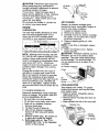
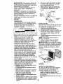
AIR CLEANER
Service air cleaner cartridge every
twenty-five hours, more often if engine is
used in very dusty conditions.
1. Loosen air cleaner screw.
2. Remove air cleaner cover.
3. Carefully remove air cleaner cartridge.
Be careful. Do not allow dirt or debris
to fall into carburetor.
4. Clean by tapping gently on a flat
surface.
NOTE: If very dirty or damaged, replace
cartridge.
5. Clean and replace cover. Tighten
screw securely.
_CAUTION:
Petroleum solvents, such as
kerosene, are not to be used to clean
cartridge. They may cause deterioration
of the cartridge. Do not oil cartridge. Do
not use pressurized air to clean or dry
cartridge.
Air Cleaner Cartridge
Cover
Air
Cleaner
Screw
COOLING SYSTEM
Your engine is air cooled. For proper
engine performance and long life keep
your engine clean.
• Clean air screen frequently using a
stiff-bristled brush.
• Remove blower housing and clean as
necessary.
• Keep cylinder fins free of dirt and chaff.
Muffler
Cylinder
Fins
Housing
12
MUFFLER
CLEANING
Do not operate tiller without muffler. Do
not tamper with exhaust system. Damaged mufflers or spark arresters could
create a fire hazard. Inspect periodically
and replace if necessary. If your engine is
equipped with a spark arrester screen assembly, remove every 50 hours for cleaning and inspection. Replace if damaged.
SPARK PLUG
Do not clean your tiller when the engine
and transmission are hot. We do not
recommend using pressurized water
(garden hose, etc.) to clean your unit
unless the gasket area around the
transmission and the engine muffler, air
filter and carburetor are covered to keep
water out. Water in engine will shorten
the useful life of your tiller.
• Clean engine, wheels, finish, etc. of all
foreign matter.
• Keep finished surfaces and wheels free
of all gasoline, oil, etc.
• Protect painted surfaces with automotive type wax.
Replace spark plugs at the beginning of
each tilling season or after every 50
hours of use, whichever comes first.
Spark plug type and gap setting are
shown in "PRODUCT SPECIFICATIONS"
on page 4 of this manual.
TRANSMISSION
Your transmission is sealed and will not
require lubrication unless serviced.
_CAUTION:
Disconnect spark plug wire
from spark plug and place wire where it
cannot come into contact with plug.
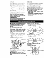
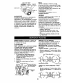
NORMAL TILLING - 26" PATH
• Assemble holes "A" in tine hubs to
holes "B" in tine shaft.
TILLER
TO ADJUST HANDLE HEIGHT
Factory assembly has provided lowest
handle height. Select handle height best
suited for your tilling conditions.
Handle
height will be different when tiller digs
into soil.
1. If a higher handle height is desired,
loosen the four nuts secudng handle
panel to engine brackets.
2. Slide handle panel to desired location.
3. Tighten the four nuts securely.
_---
Inner Tine
MID-WIDTH TILLING - 24" PATH
• Assemble holes "A" in tine hubs to
holes "C" in tine shaft.
A
C
o
o
O
NARROW TILLING/CULTIVATING
12-3/4" PATH
• Remove outer tines.
TINEARRANGEMENT
Your outer tines can be assembled in
several different ways to suit your tilling or
cultivating needs.
• kCAUTION: Tines are sharp. Wear
gloves or other protection when handling
tines.
Outer
Tine_
Hairpin Clip
Engine Brackets
2
on Left Side
of Tiller
Clevis Pin
Ioo ool
13
O
-
Cable Clip
NOTE: When reassembling outer tines,
be sure right fine assembly (marked "R")
and left tine assembly (marked "L") are
mounted to correct side of tine shaft.
TINE OPERATION CHECK
_kWARNING: Disconnect spark plug wire
from spark plug to prevent starting while
checking tine operation.
For proper tine operation, forward tine
control lever must be against control body
and all slack removed from inner wire of
control cable when control is in the "OFF"
(up) position.
If lever and cable are loose, loosen cable
clip at lower end of cable. Pull up on
cable to remove slack, without extending
spring on end of cable, and retighten
cable clip.
FINAL CHECK "OFF" POSITION
1. With tine control "OFF" (up), push
down on handle to raise tines off the
2. Slowly pull recoil starter handle while
observing tines. Tines should not
rotate.
3. If tines rotate, inner wire of control
cable is too tight which is extending
lower spring and engaging tines.
Loosen cable clip and push down on
cable only enough to relieve spring
tension. Tighten cable clip.
4. Recheck in "OFF" position and adjust
if necessary.
FINAL CHECK "ON" POSITION
5. With tine control "ON" (held down to
handle) push down on handle to raise
tines off the ground.
6. Slowly pull recoil starter handle while
observing tines. Tines should rotate
forward.
7. If tines do not rotate, inner wire of
control cable is too loose. Loosen
cable clip and pull cable up to remove
slack and retighten clip.
8. Recheck in "ON" position and adjust if
necessary.
NOTE: If "ON" position check required
adjustment, recheck "OFF" position
adjustment to insure tines do not rotate
when control is "OFF" (up).
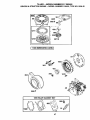
TO REMOVE BELT GUARD
t.
Remove two (2) cap nuts and washer_
from side of belt guard,
2. Loosen (do not remove) tine shield
nut on underside of tine shield.
3. Pull belt guard out and away from unit
4. Replace belt guard by reversing
above procedure.
Be sure slot in
bottom of belt guard is under head of
tine shield bolt and all nuts are
tightened securely.
Nuts and
Washer
Guard
TO REPLACE
V-BELTS
Replace V-belts if they have stretched
considerably or if they show cracks or
frayed edges. There are two (2) V-belts forward (inside) and reverse (outside).
1. Belt guard must be removed to service
belts. See "TO REMOVE BELT
GUARD" in this section of manual.
NOTE: Observe carefully routing of both
belts and location of all belt guides before
removing belts.
BELT REMOVAL
2. Remove reverse idler pulley from idler
arm.
3. Remove reverse (outside) V-belt.
4. Remove forward (inside) V-belt from
transmission pulley first and then from
engine pulley.
BELT REPLACEMENT
Tine Control "OFF"
Positiion.
Tin,
"ON" Position
Tine Control Cable
14
5. Install new forward (inside) V-belt to
engine pulley first then to transmissior
pulley. Be sure belt is positioned on
inside groove of both pulleys, inside
all belt guides and rests on idler
pulley.
6. Before installing reverse (outside) Vbelt, turn belt "inside out". Twist so
wide, flat surface of belt is to inside.
7. Wrap V-belt around reverse idler
pulley and reassemble idler to idler
arm. Tighten securely. Be sure belt is
between reverse idler pulley and idler
arm pin.
8. Install belt to outside groove of
transmission pulley. Be sure belt is
inside all beltguides and rests on
outside groove of engine pulley.
CHECK TINE OPERATION
9. See "TINE OPERATION
this section of manual.
10. Replace belt guard.
FRONT
Reverse
VIEW
Idler Pulley.
CHECK"
S_\
MOTION
ine Pulley
Idler
Arm Pin
Pulley
Bel'
Forward
in
REFERENCE
Idler Arm Pin
(INSIDE)V-BELT
Guide
Idler Pulley
Belt Guide
Idler
Pulley
TransmissionPulley
REVERSE (OUTSIDE) V-BELT
Reverse Idler Pulley
V-Belt
Reverse
Idler
Idler Pulley
Engine Pulley
FORWARD
Reverse Idler Arm Reverse (OUTSIDE)
Guard
Bolt
Transmission Pulley
ENGINE
Maintenance, repair, or replacement of
the emission control devices and systems, which are being done at the
customers expense, may be performed
by any non-road engine repair establishment or individual. Warranty repairs must
be performed by an authorized engine
manufacturer's service outlet.
TO ADJUST CARBURETOR
The carburetor has been preset at the
factory and adjustment should not be
necessary. However, engine performance can be affected by differences in
fuel, temperature, altitude or load. If the
carburetor does need adjustment, contact
your nearest authorized service center/
department
IMPORTANT:
Never tamper with the
engine governor, which is factory set for
proper engine speed. Overspeeding the
engine above the factory high speed
setting can be dangerous.
If you think the
engine-governed
high speed needs
adjusting, contact your nearest sears or
other qualified service center which has
the proper equipment and experience to
make any necessary adjustments.
15
Immediately prepare your tiller for storage
at the end of the season or if the unit will
not be used for 30 days or more.
_CAUTION:
Never store the tiller with
gasoline in the tank inside a building
where fumes may reach an open flame or
spark. Allow the engine to cool before
storing in any enclosure.
TILLER
1. Clean entire tiller (See "CLEANING" in
the Maintenance section of this
manual).
2. Inspect and replace belts, if necessary
(See belt replacement instructions in
the Service and Adjustments section
of this manual).
3. Lubricate as shown in the Maintenance section of this manual.
4. Be sure that all nuts, bolts and screws
are securely fastened. Inspect moving
parts for damage, breakage and wear.
Replace if necessary.
5. Touch up all rusted or chipped paint
surfaces; sand lightly before painting.
ENGINE
FUEL SYSTEM
IMPORTANT: It is important to prevent
gum deposits from forming in essential
fuel system parts such as the carburetor,
fuel filter, fuel hose, or tank during
storage. Also, alcohol blended fuels
(called gasohol or using ethanol or
methanol) can attract moisture which
leads to separation and formation of
acids during storage. Acidic gas can
damage the fuel system of an engine
while in storage.
1. Drain the fuel tank.
2. Start the engine and let it run until the
fuel lines and carburetor are empty.
• Never use engine or carburetor cleaner
products in the fuel tank or permanent
damage may occur.
• Use fresh fuel next season.
NOTE: Fuel stabilizer is an acceptable
alternative in minimizing the formation of
fuel gum deposits during storage. Add
stabilizer to gasoline in fuel tank or
storage container. Always follow the mix
ratio found on stabilizer container. Run
engine at least 10 minutes after adding
stabilizer to allow the stabilizer to reach
the carburetor. Do not drain the gas tank
and carburetor if using fuel stabilizer.
ENGINEOIL
Drain oil (with engine warm) and replace
with clean oil. (See =ENGINE" in the
Maintenance section of this manual).
CYLINDER
1. Remove spark plug.
2. Pour 1 ounce (29 ml) of oil through
spark plug hole into cylinder.
3. Pull starter handle slowly several
times to distribute oil.
4. Replace with new spark plug.
OTHER
• Do not store gasoline from one season
to another.
• Replace your gasoline can if your can
starts to rust. Rust and/or dirt in your
gasoline will cause problems.
• If possible,.store your unit indoors and
cover it to give protection from dust and
dirt.
• Cover your unit with a suitable protective cover that does not retain moisture.
Do not use plastic. Plastic cannot
breathe which allows condensation to
form and will cause your unit to rust.
IMPORTANT: Never cover tiller while
engine and exhaust areas are still warm.
16
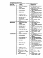
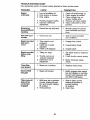
TROUBLE
SHOOTING
CHART:
See appropriate section in manual unless directed to Sears service center.
PROBLEM
CAUSE
CORRECTION
Will not start
1. Out of fuel.
2. Engine not "CHOKED"
properly.
3. Engine flooded.
4. Dirty air cleaner.
5. Water in fuel.
6. Clogged fuel tank.
7. Loose spark plug wire.
8. Bad spark plug or
improper gap.
9. Carburetor out of adjustment.
10.Oil soaked air filter.
Hard to start
1. Throttle control not set
properly.
2. Dirty air cleaner.
3. Bad spark plug or
improper gap.
4. Stale or dirty fuel.
5. Loose spark plug wire.
6. Carburetor
ment.
Loss of power
out of adjust-
1. Engine is overloaded.
2. Dirty air cleaner.
3. Low oil level/dirty oil.
4. Faulty spark plug.
5. Oil in fuel.
6. Stale or dirty fuel.
7. Water in fuel.
8. Clogged fuel tank.
9. Spark plug wire loose.
10.Dirty engine air screen.
11 .Dirty/clogged muffler.
12.Carburetor out of adjutsment.
13.Poor compression.
17
1. Fill fuel tank.
2. See "TO START ENGINE" in
the Operation section.
3. Wait several minutes before
attempting to start.
4. Clean or replace aircleaner
cartridge.
5. Drain fuel tank and carburetor, and refill tank with fresh
gasoline.
6. Remove fuel tank and clean.
7. Make sure spark plug wire is
seated properly on plug.
8. Replace spark plug or adjust
gap.
9. Make necessary adjust
ments.
10.Replace air filter.
1. Place throttle control in
"FAST" position.
2. Clean or replace air cleaner
cartridge.
3. Replace spark plug or adjust
gap.
4. Drain fuel tank and refill with
fresh gasoline.
5. Make sure spark plug wire is
seated properly on plug.
6. Make necessary adjust
merits.
1. Set depth stake and wheels
for shallower tilling.
2. Clean or replace aircleaner
cartridge.
3. Check oil level/change oil.
4. Clean and regap or change
spark plug.
5. Drain and clean fuel tank
and refill, and clean carbure
tor.
6. Drain fuel tank and refill
with fresh gasoline.
7. Drain fuel tank and carburetor, and refill tank with fresh
gasoline.
8. Remove fuel tank and clean.
9. Connect and tighten spark
plug wire.
10.Clean engine air screen.
11.Clean/replace
muffler.
12.Make necessary adjustments.
1&Contact a Sears or other
qualified service center.
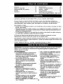
TROUBLE SHOOTING CHART:
See appropriate section in manual unless directed to Sears service center.
PROBLEM
Engine
overheats
CAUSE
CORRECTION
1. Low oil level/dirty oil.
2. Dirty engine air screen.
3. Dirty engine.
4. Partially plugged muffler.
5. Improper carburetor
adjustment.
1. Check oil level/change oil.
2. Clean engine air screen.
3. Clean cylinder fins, air
screen, muffler area.
4. Remove and clean muffler.
5. Adjust carburetor to richer
position.
Excessive
bounce/difficult
handling
1. Ground too dry and hard.
1.
Soil balls up or
clumps
1. Ground too wet.
1. Wait for more favorable
soil conditions.
Engine runs but
tiller won't
move
1. Tine control is not
engaged.
2. V-belt not correctly
adjusted.
3. V-belt is off pulley(s).
1. Engage tine control.
Engine runs but
labors when
tilling
1. Tilling too deep.
2. Throttle control not
properly adjusted.
3. Carburetor out of
adjustment.
Tines Skip
over ground
1. Shear pin (s) broken.
Hard to Shift
into gear
1. Gears not timmed.
Tiller shuts off
when drive
control bar
engaged
1. Shift lever set in between
counter rotating till position and forward rotating
till position.
2. Tines jammed.
2.
Inspect/adjust
or wait for
soil condi-
V-belt.
3. Inspect V-belt.
1. Set depth stake for shallower
tilling.
2. Check throttle control setting.
3. Make necessary
meats.
1. Replace
.
18
Moisten ground
more favorable
tions.
adjust
shear pin(s).
Briefly engage drive control
bar and release or rock tiller
forward and backward until
are able to shift gears.
1. Shift to either counter
rotating till position or
forward rotating
till position.
2. Clear tines.
Garantia ......................................................
Reglas de Seguridad ...................................
Especificaciones
del producto ....................
Montaje ........................................................
Operacion ....................................................
GARANTIA
LIMITADA
19
19
21
22
24
Mantenimiento .............................................
29
Programa de Mantenimiento ....................... 29
Servicio y Ajustes ......................................
31
Almacenamiento ..........................................
35
IdentificaciSn de Problemas ........................ 36
Vea el manual Ingl6s del duefio .. Back Cover
DE DOS AI_IOS PARA LA CULTIVADORA
CRAFTSMAN
Por dos (2) afios, a partir de la fecha de compra, cuando esta Cultivadora Craftsman se
mantenga, lubrique y afine segun las instrucciones para la operaci6n y el mantenimiento en el
manual del duefio, Sears reparara., gratis, todo defecto en el material y la mano de obra.
Esta Garantia no cubre:
• Articulos que se desgastan durante el uso normal tales como los brazos, las bujias, los filtros
de aire y las correas.
• Reparaciones necesarias debido al abuso o a la negligencia del operador, incluy6ndose a los
cigi_efiales doblados y a la falta de mantenimiento del equipo segen las instrucciones que se
incluyen en el manual del duefio.
• Si la Cultivadora Craftsman se usa para fines de arriendo, esta garantfa se aplica solamente
por treinta (30) treintadfas a partir de la fecha de compra.
El Servicio de Garantia esta disponible al devolver la cultivadora Craftsman
departamento de servicio Sears m_.s cercano en los estados unidos.
al centro/
Esta Garantia se aplica solamente mientras el producto este en uso en los estados unidos. Esta
Garantfa le otorga derechos legales especfficos, y puede que tambi6n tenga otros derechos que
varian de estado a estado.
SEARS, ROEBUCK
AND CO., D/817WA,
HOFFMAN
ESTATES,
IL 60179
IMPORTANTE" Esta Maquina cortadora es capaz de amputar las manosy los pies y de lanzar
objetos, si no se observan las instrucciones de seguridad siguientes se pueden producir
lesiones graves o la muerte.
ENTRENAMIENTO
• Lea el Manual del Duefio cuidadosamente.
Familiarfcese completamente con los
controles y con el uso adecuado del equipo.
Sepa cbmo parar la unidad y desenganchar
los controles r&pidamente.
• Nunca permita que los nifios operen el
equipo. Nunca permita que los adultos
operen el equipo sin los conocimientos
adecuados.
• Mantenga el &rea de operaci6n despejada
de personas, especialmente nifios
pequefios y animales dom_sticos.
PREPARACl6N
• Inspeccione cuidadosamente el &rea en
donde se va usar el equipo y remueva los
objetos extrafios.
• Desenganche todos los embragues y
cambie a neutro antes de hacer arrancar el
motor.
• No opere el equipo sin usar ropa exterior
adecuada. Use zapatos que mejoren el
equilibrio en superficies resbalosas.
• Maneje el combustible con cuidado pues es
muy inflamable.
• Use un envase de combustible aprobado.
• Nunca afiada combustible a un motor en
funcionamiento o caliente.
• Llene el estanque de combustible afuera
con mucho cuidado. Nunca Ilene el
estanque de combustible en un recinto
cerrado.
• Vuelva a colocar la tapa del dep6sito de
gasolina en forma segura y limpie el
combustible derramado antes de volver a
arrancar.
• Use cordones de extensi6n y recept_.culos,
segen las especificaciones
del fabricante,
para todas las unidades con motores de
impulsi6n o con motores de arranque
electrico.
• Nunca trate de hacer ningen ajuste
mientras que el motor este funcionando
(excepto en los casos especfficamente
recomendados por el fabricante).
OPERACI(_N
• No ponga ni las manos ni los pies cerca o
debajo de las piezas rotatodas.
19
• Tenga mucho cuidado cuando opere o
cruce entradas para autom6viles de ripio,
senderos o caminos. Est_ alerta en Io que
se refiere a los peligros escondidos o al
trafico. No Ileve pasajeros.
• Despues de pegarie a un objeto extraSo,
pare el motor, remueva el alambre de la
bujia, inspeccione la cultivadora
cuidadosamente,
para verificar si hay
da£1os, y repare el daSo antes de volve_ a
arrancar y operar la cultivadora.
• Tenga cuidado para evitar resbalarse o
caerse.
• Si la unidad empieza a vibrar anormalmente,
pare el motor y revfsela inmediatamente
para verificar la causa. La vibraci6n
normalmente es un aviso de problemas.
• Pare el motor cuando abandone la posicion
de operaciSn.
• Tome todas las precauciones posibles
cuando deje la m_.quina desatendida.
Desenganche los brazos, cambie a neutro
y pare el motor.
• Antes de limpiar, reparar e inspeccionar,
apague el motor y aseg=3rese que todas las
partes en movimiento se han detenido.
Desconecte el alambre de la bujia, y
mantengalo alejado de _sta para evitar el
arranque por accidente. Desconecte el
cord(Sn en los motores electricos.
• No haga funcionar el motor en recintos
cerrados; los gases de escape son
tn_d;qrosos.
• r" :; ,'_ opere la cultivadora sin las
piui_,_.ul011e$,
•
•
•
•
•
•
•
y
Ido
plallchas
adeCu_u,_o
y
sin los dem&s dispositivos de seguridad en
su lugar.
Mantenga a los nii_os y a los animales
dom_sticos alejados.
No sobrecargue la capacidad de la
m_.quina, tratando de cultivar a mucha
profundidad, muy r_lpido.
Nunca opere la maquina a altas velecidades
en superficies resbalosas. Mire hacia atr_.s
y tenga cuidado cuando retroceda.
Nunca permita la presencia de
espectadores cerca de la unidad.
Use sOlamente accesorios y aditamentos
para la cultivadora aprobados por el
fabricante.
Nunca opere la cultivadora sin buena
visibilidad o luz.
Tenga cuidado al cultivar en terreno duro.
Los brazos pueden quedarse agarrados en
el suelo e impulsar a la cultivadora hacia
adelante. Si esto sucede, suelte los mangos
y no restrinja la m&quina.
MANTENIMIENTO
ALMACENAMIENTO
Y
• Mantenga los aecesodos y aditamentos de
la m_quina en buenas condiciones para el
funcionamiento.
• Revise las clavijas de seguro, los pernos de
montaje del motor y otros pernos, a
intervalos frecuentes, para verificar si estan
apretados en forma segura y asegurarse
que el equipo este en buenas condiciones
de funcionamiento.
• Nunca guarde la maquina con combustible
en el estanque de combustible dentro de un
edificio en donde hay fuentes de ignicibn
presentes, tales como calentadores de
agua o del ambiente, secadoras de ropa u
otros artefactos parecidos. Permita que se
enfrie el motor antes de guardarlo en algt_n
lugar cerrado.
• Siempre refi4rase alas instrucciones en la
guia del operador para ver los detalles de
importancia si la cultivadora va a ser
guardada por un per{odo de tiempo largo.
_l,Busque este simbo!o que se_ala las
precauciones de seguridad de importancia.
Quiere decir - iiiATENCION!f!
iiiESTE
ALERTO!!! SU SEGURIDAD ESTA COMPROMETIDA.
APRECAUCION:
Siempre desconecte el
alambre de la bujia y p6ngalo donde no pueda
entrar en contacto con ia bujfa, para evitar el
arranque por accidente, durante la
preparaci6n, el transporte, el ajuste o cuando
_e l,,nr.'_n
repara_:i,_nes.
_JI,ADVERTENClA:
El tubo de escape del
motor, algunos de sus constituyentes y
algunos componentes del vehiculo contienen
o desprenden productos quimicos conocidos
en el Estado de California como causa de
cancer y defectos al nacimiento u otros daSos
reproductivos.
20
ESPECIFICACIONES
DEL PRODUCTO
Capacidad de
Gasolina:
3 Cuartos
Sin plomo, Regular
Aceite (API-SF-SJ):
(Capacidad: 20 oz.)
SAE 30 (Sobre 32°F)
SAE 5W-30 (Debajo 32°F)
Bujia :
(Abedura:0,030")
Champion
RC12YC
RESPONSABILIDADES
DEL CLIENTE
• Lea y observe las reglas de seguridad.
• Siga un programa regular de mantenimiento,
cuidado y uso de eu cultivadora.
• Siga las instrucciones descritas en las
secciones "Mantenimiento ° y
"Almacenamiento"
de este Manual del
Due5o.
_kADVERTENClA:
Esta unidad viene
equipada con un motor de combusti6n intemo
y no se debe usar sobre, o cema, de un
terreno no desarrollado cubierto de bosques,
de arbustos o de c_sped, a menos que el
sistema de escape del motor venga equipado
con un amortiguador de chispas que cumpla
con las leyes locales o estatales (si existen).
Si se usa un amortiguador de chispas, el
operador debe mantenerlo en condiciones de
trabajo eficientes.
En el estado de California, la ley exige Io
anterior (Secci6n 4442 del "California Public
Resources Code" [Decreto de Recursos
Peblicos de California]).
Otros estados
pueden contar coo otras leyes parecidas. Las
leyes federales se aplican en las tierras
federales. Su centro de Servicio mas cercano
tiene disponible amortiguadores de chispas
para el silenciador. (Vea la secci6n de Partes
de Repuesto en el manual Ingles del duefio.)
FELIClTAClONES
por la compra de su
Cultivadora Sears. Ha sido diseSada,
planificada y fabricada para darle la mejor
confiabilidad y el mejor rendimiento posible.
En el caso de que se encuentre con cualquier
problema que no pueda solucionar facilmente,
haga el favor de ponerse en contacto con un
centro de servicio Sears o con un otro centro
de servicio cualificado. Cuenta con t_cnicos
bien capacitados y competentes con
herramientas adecuadas para darle servicio o
para reparar su unidad.
Haga el favor de leer y de guardar este
manual. Estas instrucciones le permitir&n
montar y mantener su cultivadora en forma
adecuada. Siempre observe las "REGLAS DE
SEGURIDAD."
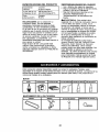
Estos accesorios estaban disponibles cuando se compr6 la cultivadora. Tambi_n est_.n
disponibles en la mayoda de las tiendas de Sears yen los centros de servicio. La mayoria de las
tiendas Sears tambi_n pueden ordenar partes de repuesto para usted, si les proporciona el
nemero del modelo de su cultivadora.
MOTOR
MANTENIMIENTO
CORREA
DE LA CULTIVADORA
BRAZOS
CLAVIJA
DE SEGURO
0
21
ABRAZADERA
DE HORQUILLA
Su cultivadora nueva ha sido montada en la
fabrica, con la excepci6n de aquellas partes
que se dejaron sin moRtar por razones de
envfo. Para asegurarse que la cultivadora
operara en forma segura y adecuada, todas
las partes y los artfculos de ferreterfa que
monte tienen que estar apretados en forma
segura. Use las herramientas correctas,
segun sea necesario, para asegurarse de
que queden apretadas en forma segura.
HERRAMIENTAS
NECESARIAS
PARA
EL MONTAJE
Se le facilitara el montaje si cuenta con un
juego de Ilaves de tubo. Se han enumerado
los tamafios estandar de las Ilaves.
(1) Cuchillo para todo uso
(1) Par de alicates
(1) Desatornillador
(2) Llave de 1/2"
POSICI6N
DEL OPERADOR
Cuando en este manual se mencionan los
terminos "lado derecho" o "lado izquierdo" se
refiere a cuando usted se encuentra en la
posicion de operaci6n (parado/a detr,_s de los
mangos de la cultivadora).
ParleDelantera
Lado
Izquierdo
Lado
Derecho
Posicion del operador
CONTENIDO DEL COHJUHTO DE FERRETER[A
_(2)
Pernos
5/16-18
portadore_
Q
UNC x 2-1/2
(2) Tuercas
(1) Manual
seguridad
de
de brida
© Q
0,,0-, UN
(1) Aceite
(1) Perno
hexagonales
5/16-18 x 1-1/4
del motor
22
(1) Arandela
seguridad
de
5/16
(1) Tuerca
hexagonales
5/16-18
DESEMPAQUE
DE LA CAJA DE
CARTON
E INSTALACI6N
DEL MANGO
_PRECAUCI(_N:
Tenga cuidado con las
grapas expuestas cuando maneje o deseche
los matedales de la caja de cart6n.
IMPORTANTE:
Cuando desempaque y monte
la cultivadora, tenga cuidado de no estirar o
enredar el (los) cable(s).
1. Corte las abrazaderas de cable que
aseguran la columna del mango.
2. Inserte el cable segun Io mostrado y
resbale la columna del mango sobre la
montura del mango.
3. Remueva el empaque de la caja de cart6n.
4. Asegure la columna del mango usando
dos (2) pernos de acarreo y dos (2)
contratuercas con aletas. Apriete con
seguridad.
5. Corte la caja de cart6n.
6. Haga pasar el cable de control de los
brazos a trav_s de la abrazadera los
cables de pl_,stico en ia montura del
mango.
AVISO: Los cables no deben tocar el
silenciador.
7. Corte las ligaduras del cable que aseguran
la cultivadora a la corredera.
Remueva la
cultivadora de la corredera tirdndola hacia
atrds.
8. Quitar el tornillo de fijaci6n del pilote de
profundidad para girar y remover el tornillo.
INSTALACION
DEL CONJUNTO
DE LA
ESTACA DE PROFUNDIDAD
1. Aflojar la tuerca "A".
2. Quitar la tuerca hexagonal, la arandela de
bloqueo y el bul6n de fijaci6n del sopode del
pilote de profundidad alas bridas del motor.
Guardar estas pades para el sucesivo
ensamblaje.
3. Levantar y posicionar el soporte del pilote
de profundidad para alinear los agujeros en
el soporte con los agujeros "B" y "C" en las
bridas del motor.
4. Instalar en los agujeros "B" y "C" las partes
removidas antes y una (1) parte de
quincalleria de la bolsa de las partes.
Apretar los dos bulones de modo firme.
5. Apretar la turca "A"
6. Ensamblar el pilote de profundidad entre los
sopodes del pilote de profundidad con el
la abrazadera.
\
Tuerca "A"
Pemo hexagonales
tuerca hexagonales
Soporte de la estaca
de profundidad
/
I
Montura del mango
Mitades del puntal del motor
T? rca "A"
! ",_," Soporte de la estaca
Control de los
brazos
de los brazo N
0p0,=0
tJJl/_
_-_
J,_/_
J
Perno de soporte
Abrazaderade
/_
horquillay clavija
\
de horquilla
Resorte de
Agujeros "B" y =C" la estaca
Pernos hexagonales, arandelas de
seguddad y tuercas hexagonales
ALTURA
DEL MANGO
• Se puede ajustar la altura del mango en la
mejor forma que le acomode al operador.
(Vea "ALTURA DEL MANGO" en la secci6n
de Servicio y Ajustes de este manual,)
ANCHO DEL LABRADO
• Se puede ajustar el ancho del labrado para
manejar mejor sus condiciones de labraci6n
(vea "ARREGLO DE LOS BRAZOS" en la
secci6n de Servicio y Ajustes de este
manual).
OPERACl6N
DE LOS BRAZOS
Pemo
f
portadores
Tuercade
seguridadde
brida
• Revise la operaci6n de los brazos antes del
primer uso (yea "REVISI6N DE LA
OPERACION DE LOS BRAZOS en la
seccibn de Servicio y Ajustes de este
23
manual).
CONOZCA SU CULTIVADORA
LEA ESTEMANUALDELDUEllOY LAS REGLAS
DE SEGURIDAD ANTES DE OPERAR SU
CUTIVADORA
Compare las ilustraciones con su cultivadora para familiarizarse con la ubicaci6n de los diversos
controles y ajustes. Guarde este manual para referencia en el futuro.
Estos simbolos pueden apareser sobre su cultivadora
el producto.
Aprenda y comprenda sus significados.
en la literatura
proporcionada
con
Control de los brazos marcha arras
Control de los brazos
marchahacia adelante
Control de la estrangualci6n
Control de la
aceleraci6n
Estaca de profundidad
Mango del arrancadorde
culateo
O
Las cultivadoras de Sears cumplen con los estdndares de seguridad del
American National Standard Institute (Instituto Nacional de Estdndares Amedcano).
CONTROL DE LOS BRAZOS MARCHA
CONTROL DE LA ACELERACI6N
Controla la velocidad del motor.
HACIA ADELANTE - Engancha los brazos
en la direcci6n de marcha hacia adelante,
" ESTACA DE PROFUNDIDAD
-Controla la
CONTROL DE LOS BRAZOS MARCHA
velocidad de la marcha hacia adelante y la
HACIA ATRAS - Engancha los brazos en la
profundidad a la cual excavard la cultivadora.
direcci6n de marcha hacia atrds.
MANGO DEL ARRANCADOR
DE CULATEO
CONTROL DE LA ESTRANGULAClON
- Se usa para hacer arrancar el motor.
Uselo cuando se hace arrancar un motor frfo,
24
La operaci6n de cualquier cultivadora puede hacer que salten objetos extra,_os
dentro de sus ojos, Io que puede producir daSos graves en estos. Siempre use
anteojos de seguridad o protecciones para los ojos antes de hacer arrancar su
cultivadora o mientras este labrando con _lla. Recomendamos el uso de la
m&scara de seguridad de visi6n amplia, para uso sobre los espejuelos o anteojos
de seguridad est_lndar.
Tambi6n, mientras m_.s se baje la estaca de
COMO USAR SU CULTIVADORA
profundidad dentro del suelo, m_.s profunda
Sepa como operar todos los controles antes
ser_l la excavaci6n realizada con los brazos.
de agregar combustible y aceite o antes de
tratar de hacer arrancar el motor.
ESTACA
DE PROFUNDIDAD
Ajuste
la
estaca
de profundidad removiendo la
PARADA
abrazadera
de
horquilla
y la clavija de
BRAZOS
horqui!la.
Cambie
la
estaca
de profundidad a la
1. Suelte el control del movimiento hacia
posici6n deseada. Vuelva a colocar la clavija
adelante de los brazos para parar el
de horquilla y la abrazadera de horquilla.
movimiento.
• Para el labrado normal, ajuste la estaca de
2. Suelte el control del movimiento hacia
profundidad en el segundo o tercer agujero
atras de los brazos para parar el
a partir de la parte superior.
movimiento.
RUEDAS
MOTOR
Ajuste las ruedas removiendo la abrazadera
• Musva el control de la aceleraci6n a la
de horquilla y la clavija de horquiila. Cambie la
posici6n de "PARADA" (STOP).
posici6n de la rueda. Vueiva a colocar la
AMISO: Nunca use la estrangulaci6n para
abrazadera de horquilla y la clavija de
parar el motor.
horquilla.
Control de los brazos
Control de los brazos en la
• Para el labrado normal, ajuste las ruedas en
marcha atrds
\
posici6n de "Apagado"
el segundo o tercer agujero a partir de la
parte superior.
\
Abrazadera de horquilla y
clavija de horuilla
IJJf
de "Encendido" (Abajo)
Control de la
aceleraci6n
profundidad
Control de la
estrangl
Resortede la estaca
OPERAClON
DE LOS BRAZOS
MARCHA HAClA ADELANTE
• Apriete el control de los brazos contra el
mango,
MARCHA ATRAS
• Con el control de los brazos de marcha
hacia adelante en la posici6n de
"APAGADO" (OFF) (arriba), tire hacia atrds
y sujete el control de los brazos marcha
atr&s.
LABRADO
La velocidad y la profundidad del labrado son
reguladas por medio de la posici6n de la
estaca de profundidad y por la altura de la
rueda.
La estaca de profundidad siempre tiene que
estar por debajo de las ruedas para excavar.
Sirve de freno para retardar el movimiento de
rnarcha hacia adelante de la cultivadora, para
permitir que los brazos penetren en el suelo,
PARA EL TRANSPORTE
_PRECAUCI6N:
Antes de levantarla o
transportada, permita que el motor de la
cultivadora y el silenciador se enfden.
Desconecte el alambre de la bujia. Drene la
gasolina del estanque de combustible.
EN EL JARD|N
1. Incline la estaca de profundidad hacia
adelanta, hasta que quede sujeta con el
resorte de la estaca.
2. Empuje los mangos de la cultivadora hacia
abajo, levantando los brazos por encima
del suelo.
3. Tire o empuje la cultivadora a la ubicaci6n
deseada.
EN LA ClUDAD
1. Desconecte el alambre de la bujfa.
2. Drene el estanque de combustible.
3. Transp6rtela en la posicibn derecha hacia
arriba para evitar la fuga del aceite.
25
ANTES DE HACER ARRANCAR
EL
MOTOR
IMPORTANTE: Tenga mucho cuidado de no
permitir que entre mugre al motor cua do
revise o anada aceiteo combustible. Use
aceite y combustible limpios y guardelos en
envases aprobados, limpios y con tapa. Use
embudos para relleno limpios.
RELLENO DEL ACEITE DEL MOTOR
1. Remueva la etiqueta del motor.
2. Con el motor nivelado, remueva el tapbn
del depbsito de relleno del aceite del motor.
3. Llene el motor con aceite hasta el punto de
derramarse.
Para verificar la capacidad
aproximada vea "ESPECIFICAClONES
DEL PRODUCTO ° de este manual.
4. Incline la cultivadora hacia atr&s en sus
ruedas y luego vuelva a nivelarla.
5. Con el motor nivelado, vuelva a lienarlo
hasta el punto de derramarse, si es
necesario. Vuelva a colocar el tap6n del
dep6sito de relleno de aceite.
• Para la operaci6n en clima frio, debe
cambiarse el aceite para facilitar el arranque
(vea la "TABLA DE VISCOSIDAD DEL
ACEITE" en la secci6n de Mantenimiento en
este manual).
• Para cambiar el aceite del motor, vea la
secci6n de Mantenimiento en este manual.
Nivei del
aceite
arrancar el motor y h&galo funcionar hasta
que las Ifneas del combustible y el carburador
queden vac/as. La prbxima temporada use
combustible nuevo. Vea la secci6n de
Almacenamiento para m,_s informaci6n. Nunca
use productos de limpieza para el motor o
para el carburador en el estanque del
combustible pues se pueden producir dafios
permanentes.
_qLPRECAUCI6N: Llene el estanque de
combustible hasta dentro de 1/2 pulgada de la
parte superior para evitar los derrames y para
permitir que se expanda el combustible. Si por
casualidad se derrama la gasolina, aleje la
ma.quina del area del derrame. Evite crear
cualquiera fuente de ignicion hasta que se
hayan desaparecido los gases de la gasolina.
No Io Ilene demasiado. Limpie el aceite o el
combustible derramado. No guarde, derrame o
use la gasolina cerca de una llama expuesta.
PARA HACER ARRANCAR
EL MOTOR
/I, PRECAUCI6N:
Mantenga control de los
brazos posici6n "Apagado" cuando haga
arrancar el motor.
Cuando este empezando un motor por la
primera vez o si el motor se ha quedado sin
gasolina, sera necesario varios intentos para
mover la gasolina desde el estanque al motor.
1. Aseg_rese que el alambre de la buj_a este
conectaclo en forma adecuada y que la
valvula de cierre de la gasolina este
abierta.
2. Ponga la palanca de cambio a la posici6n
de (NEUTRO) "N".
3. Ponga la palanca de cambio a la posici6n
de "RAPIDO" (FAST).
4. Mueva el control de la estrangu.laci6n a la
posicion de ESTRANGULACION.
5. Agarre el mango del arrancador de culateo
con una mano y el mango de la cultivadora
con la otra mano. Tire el cord6n hacia
afuera, lentamente, hasta que el motor
legue al comienzo del ciclo de la
compresi6n (el cord6n se sentira, un poco
mas duro en este momento).
6. Tire el mango del arrancador de culateo
rdpidamente. No permita que el mango del
arrancador se devuelva abruptamente en
contra del arrancador. Vuelva a repetir, si
Io es necessario.
AVISO: Si el motor se enciende pero no
comienza, mueva el control de la
estrangulacibn al medio. Tire del mango del
arrancador de retroceso hasta que el motor
comience.
7. Cuando comience el motor y al mismo
tiempo que se caliente, mueva,
lentamente, el control de la estrangulacibn,
a la posicibn de "MARCHA".
AVISO: Un motor caliente requiere menos
estrangulacibn para empezar.
Tapbn de
deposito
de relleno de
aceite
AGREGUE GASOLINA
• Llene el estanque de combustible. Use
gasolina regular, sin plomo, nueva y limpia.
(El uso de gasolina con plomo aumentar_.
los depbsitos de bxido de plomo y carbono
y se reducir_, la duracibn de la v&lvula.)
IMPORTANTE. Cuando se opere en
temperaturas por debajo de 32°F (0°C) use
gasolina de calidad de invierno, limpia y nueva
para ayudar a asegurar un buen arranque en
clima fdo.
• I=PRECAUCI(_N" Los combustibles
mezclados con alcohol (conocidos como
gasohol, o el uso de etanol o metanol) pueden
atraer la humedad, la que conduce a la
separacibn y formacibn de &cidos durante el
almacenamiento. La gasolina acfdica puede
dafiar el sistema del combustible de un motor
durante el almacenamiento. Para evitar
problemas con el motor, se debe vaciar el
sistema de combustible antes de
guardarlo por un per|odo de 30 alias o
m_s. Vacfe el estanque de combustible, haga
26
8.
Mueva el control de la aceleraci6n a la
posici6n de funcionamiento deseada.
9. Permita que se caliente el motor por unos
cuantos minutos antes de enganchar los
brazos.
AVISO: A mucha altura (sobre 3000 pies) o en
climas frfos (debajo de 40 ° F [4 ° C]) puede
que la mezcla del combustible del carburador
necesite ajuste, para obtener el mejor
resultado del motor. Vea "PARA AJUSTAR EL
CARBURADOR"
en la secci6n de Servicio y
Ajustes de este manual.
AVISO: Si el motor no arranca, vea la gufa de
identificaci6n de problemas.
Bujfa
Si la cultivadora esta. bien ajustada, excavara
con poco esfuerzo por parte del operador.
• El labrar quiere decir el excavar, dar vuelta
y romper el suelo duro antes de plantar. El
suelo suelto y blando permite el desarrollo
de las rafces. La mejor profundidad de
labrar es 4" a 6". La cultivadora tambi_n
puede despejar el suelo de la mala hierba
indeseables.
La descomposici6n de esta
mala hierba enriquece el suelo.
Dependiendo del clima (lluvia o viento),
puede ser recomendable labrar el suelo a
fines de la temporada de cultivo para
acondicionar el suelo aun mas.
• Las condiciones del suelo son importantes
si se desea obtener un labrado adecuado.
Los brazos no van a penetrar facilmente en
el suelo seco y duro, Io que puede contribuir
a un rebote excesivo y a dificultades en el
manejo de su cultivadora. El terreno duro
tiene que ser humedecido antes de labrarlo,
sin embargo, si el suelo esta demasiado
mojado se convertira en bolas o se
amontonara durante el labrado. Espere a
que el suelo este menos mojado para poder
obtener los mejores resultados. Cuando se
hagan labrados en el otofio, remueva las
vides y el cesped alto para evitar que se
envuelvan alrededor del eje de los brazos y
retarden su operaci6n para el labrado.
• Va a descrubrir que el labrado se facilita si
deja una ilia sin labrar entre las pasadas.
Entonces vuelva de nuevo entre las fUas de
cultivo. Hay dos razones para hacer esto.
Primero, las vueltas amplias se pueden
realizar con ma.s facilidad que las cerradas.
Segundo, la cultivadora no estara
empuj,_ndose a sf misma y a usted hacia la
proxima hilera.
• Ajuste la estaca de profundidad y la altura
de la rueda para labrado poco profundo
cuando est_ trabajando en suelo o terreno
herboso demasiado duro. Luego atraviese
los primeros cortes a la profundidad normal.
Control de la
aceleraci6n
la estrangulaci6n
Mango del
RODAJE
DE SU CULTIVADORA
Use su(s) correa(s), las poleas y el control de
los brazos antes de empezar a labrar.
• Haga arrancar el motor, saque los brazos
fuera del suelo presionando los mangos
hacia abajo y enganche el control de los
brazos para hacer arrancar la rotaci6n de
los brazos. Permita que los brazos roten por
cinco minutos.
• Revise la operaci6n de los brazos y
ajestelos, si es necesario. Vea "REVlSI6N
DE LA OPERACION DE LOS BRAZOS" en
la secci6n de Servicio y Ajustes de este
manual.
CONSEJOS
PARA LABRAR
A_,PRECAUCl6N"
Antes de acostumbrarse a
manejar su cultivadora, empiece el uso de
_sta en el terreno con la aceleraci6n en la
posicibn de "lento" (SLOW).
Para ayudarle a la cultivadora a moverse
hacia adelante, levante los mangos un poco
(levantando en esta forma la estaca de
profundidad fuera del suelo). Para hacer que
la cultivadora ande m&s lento presione los
mangos hacia abajo.
Si est,. forz&ndola o si la cultivadora est,.
vibrando, quiere decir que las ruedas y la
estaca de profundidad no est_.n ajustadas en
forma adecuada para el terreno que se esta.
labrando. El ajuste adecuado de las ruedas y
de la estaca de profundidad se Iogra al
probarlas en accibn y depende de las
condiciones del suelo. (Mientras m&s duro o
m_.s mojado est_ el suelo, menor es la
velocidad necesada del motor y de los brazos.
La cultivadora va a correr y saltar sobre el
terreno si sa usa en estas malas condiciones
a una velocidad r&pida.)
27
CULTIVO
El cultivo quiere decir la destrucci6n de la mala
hierba entre las filas para evitar que _stas le
roben la nutrici6n y la humedad alas plantas.
AI mismo tiempo, si se rompe la capa superior
de la costra del suelo, este puede retener la
humedad. La mejor profundidad de excavaci6n
es de 1" a3".
• Probablemente no va a necesitar usar la
estaca de profundidad. Empiece por inclinar
la estaca de profundidad hacia adelante,
hasta que quede sujeta en el resorte de la
estaca.
• Cultive hacia arriba y hacia abajo las filas a
una velocidad que le permita a los brazos
sacar las raices de la mala hierba y dejar el
suelo en condiciones _,speras, para impedir
e! desarrollo de la mala hierba y el cesped.
A
A
28
MANTENIMIENTO
LLENE
LAS
FECHAS
DEMEDIDA
PROGRAMA
DE
o/___,
_/__¢
SERVlClO REGULAR
HAS DE SERVICIO
Revisar el nivel del aceite del motor
V'
V'
Cambiar el aceite del motor
I_1,;`
/
Aceitar los puntos de pivote
V'
Inspeccionar el supresor del silenciador
Inspeccionar
la rejilla de aire
Limpiar/cambiar
V'
¥1
el cartucho del filtro de aire
1_2
Limpiar las aletas del cilindro del motor
V'
Cambiar la buj{a
I_
1- Carnbiar m_s menudo cuando se opere bajo carga pesada o en ambientes con alias temperaturas,
2- Dar serviciornds a rnenudocuando se opere en condicionessuciaso polvorosas
TABLA DE LUBRICACION
RECOMENDACIONES
GENERALES
La garantfa de esta cultivadora no cubre los
artfculos que han estado sujetos al abuso o a
la negligencia del operador. Para recibir todo el
valor de la garantia, el operador tiene que
mantener la cultivadora segt_n las
instrucciones descritas en este manual.
Hay algunos ajustes que se Uenen que hacer
en forma peribdica para poder mantener su
cultivadora adecuadamente.
Todos los ajustes en la seccibn de Servicio y
Ajustes de este manual Uenen que ser
revisados por Io menos una vez por cada
temporada.
• Una vez al aho, cambie la bujfa, limpie o
cambie el flltro de aire y revise si los brazos
y las correas est&n desgastadas. Una bujia
nueva y un filtro de aira limpio aseguran una
mezcla de aira-combustible adecuada y le
ayuda a que su motor funcione mejor y que
dure mds.
ANTES DE CADA USO
1. Revise el nivel del aceite del motor.
2. Revise la operacibn de los brazos.
3. Revise si hay sujetadores sueltos.
LUBRICACI(_N
* Control(_d_
** M_
* Brazo de guia
Aceite de Motor SAE30 o 10W-30
** Refierase a la secci6n del "MOTOR",
Mantenimiento
Mantenga la unidad bien !ubricada (vea la
"TABLA DE LUBRICACION").
29
_kPRECAUCI6N:
Desconecte el alambre de
la bujfa antes de dar mantenimiento (excepto
pot el ajuste del carburador) para evitar que el
motor arranque por accidente.
iEvite los incendios! Mantenga el motor sin
c_sped, hojas, aceite o combustible
derramado.
Remueva el combustible del estanque antes
de inclinar la unidad para darle mantenimiento.
Limpie el c_sped, la mugre y la basura del
d.rea del silenciador.
No toque el silenciador caliente o las aletas del
cilindro, pues el contacto puede producir
quemaduras.
MOTOR
LUBRICACI(_N
Use solamente aceite de detergente de alta
calidad clasificado con la clasificaci6n SF-SJ.
de servicio API. Seleccione la calidad de
viscosidad SAE seg0n su temperatura de
operaci6n esperada.
CALIDADES
DE VISCOSIDAD
DE SAE
AVISO: A pesar de que los aceites de
multiviscosidad
(5W-30, 10W-30, etc.)
mejoran el arranque en clima fifo, estos
aceites de multiviscosidad van a aumentar el
consumo de aceite cuando se usan en
temperaturas sobre 32°F (0°C).
Revise el nivel del aceite del motor m&s a
menudo, para evitar un posible dafio en el
motor, debido a que no tiene suficiente aceite.
Cambie el aceite despuOs de 50 horas de
operacibn o por Io menos una vez al afio si el
tiller se utiliza menos 50 horas el afio.
Revise el nivel del aceite del critter antes de
hacer arrancar el motor y despuds de cada
cinco (5) horas de uso continuado. Agregue
aceite de motor SAE 30 o su equivalente.
Apriete el tap6n del depbsito de relleno del
aceite en forma segura cada vez que revise el
nivel del aceite.
PARA CAMBIAR EL ACEITE DEL MOTOR
Determine la gama de temperatura esperada
antes del cambio del aceite. Todos los aceites
deben cumplir con los requisitos de la
clasificacibn de servicio API SF-SJ.
• Asegdrese que la cultivadora est_ en una
supefficie nivelada.
• El aceite drenar& m&s f&cilmente cuando
est,. caliente.
• Utilice un embudo para impedir el derrame
de aceite sobre la cultivadora, y recoja el
aceite en un envase adecuado.
1. Remueva el tap6n del drenaje.
2. Incline la cultivadora hacia adelante para
drenar el aceite.
3. Despu_s de que el aceite se haya drenado
completamente, vuelva a colocar el tapbn
del drenaje del aceite y apd_telo en forma
segura,
30
4.
5.
Remueva el tapbn del deposito de reUeno
de aceite. Tenga cuidado de no permitir
que la mugre entre al motor.
Vuelva a Ilenar el motor con aceite. Vea
"RELLENO DEL MOTOR CON ACEITE"
en la seccibn de Operacion de este
manual•
Tap6nde
drenaje del
aceite _.
\
•Nivel del
Tap6n del
desposito de
relleno de aceite
aceite
FILTRO DE AIRE
Dele servicio al cartucho del filtro de aire cada
50 horas y m&s a menudo si el motor se usa
en condiciones muy polvorosas.
1. Suelte los tomillo del filtro de aire.
2. Remueva la cubierta del filtro de aire.
3. Cuidadosamente, remueva el cartucho del
filtro de aire. Tenga cuidado. No permita
que mugre o basura caigan dentro del
carburador.
4. Lfmpielo golpe_.ndolo suavemente en una
superficie plana.
AVISO: Si el cartucho esta muy sucio o
dahado, reempla.celo.
5. Limpie y vuelva a colocar la cubierta.
Apriete Iostornillo en forma segura.
_I_PRECAUClON:
Los solventes de petr61eo,
tales como el kerosene, no deben ser utilizado
para limpiar el cartucho. Pueden ocasionar el
deterioro de _ste. No aceite el cartucho. No
use aire a presi6n para limpiarlo o secarlo.
Cartucho.
Caducho del filtero de aire
Cubierta
Fornillo del
filtro de aire
SISTEMA DE ENFRIAMIENTO
Su motor se enfrfa con aire. Para obtener el
rendimiento del motor adecuado y larga
duraci6n mantenga su motor limpio.
• Limpie la rejilla de aire frecuentemente
usando un cepillo de cerdas duras.
• Remueva la caja del ventilador y limpiela si
es necesario.
• Mantenga las aletas del cilindro sin mugre o
paja.
Aletas del cilindro
Caja del
ventilador
_Rejilla de
aire
BUJIA
Cambie las bujias al comienzo de cada
temporada de cultivo, o despu_s de 50 horas
de uso, Io que suceda primero. El tipo de bujfa
y la abertura aparece en las
"ESPEClFICAClONES
DEL PRODUCTO" en
la pagina 21 de este manual.
TRANSMISI6N
Su transmisi6n esta sellada y no va a
necesitar lubricaci6n.
LIMPIEZA
SILENCIADOR
No opere la cultivadora sin el silenciador. No
manipulee el sistema de escape. Los
silenciadores o los amortiguadores de chispas
daSados pueden crear un peligro de incendio.
Inspecci6nelos peri6dicamente y c_,mbielos si
es necesario. Si su motor viene equipado con
un conjunto de rejilla para el amortiguador de
chispas, remu_valo cada 50 horas para
limpiado e inspeccionarlo. C&mbielo si es
necesario.
_,PRECAUCI(_N:
Desconecte el alambre de
la bujfa y p6ngalo en donde no pueda entrar
en contacto con la bujfa.
CULTIVADORA
PARA AJUSTAR LA ALTURA DEL MANGO
El montaje en la fabrica se ha realizado
usando la altura rods baja del mango.
Seleccione la altura del mango que mejor se
acomode a sus condiciones de labraci6n. La
altura del mango sera diferente cuando la
cultivadora excave el suelo.
1. Si se desea una mayor altura para el
mango, suelte las cuatro tuercas que
aseguran el panel del mango en los
puntales del motor.
2. Deslice el panel del mango a la ubicaci6n
deseada.
3. Apriete las cuatro tuercas en forma
segura.
No limpie su cultivadora cuando el motor y la
transmisi6n esten calientes. No
recomendamos el uso de agua presurizada
(manguera del jardfn, etc.) para limpiar su
unidad a menos que el area de la junta
alrededor de la transmisi6n y del silenciador
del motor, del filtro de aire y del carburador se
cubran ara protejerlos del agua. El agua en la
transmisi6n y/o el motor acortara la vida de su
cultivadora.
• Limpie todo material extraSo del motor, las
ruedas, el pulido, etc.
• Mantenga las superficies pulidas y las
ruedas sin derrames de gasolina, aceite,
etc.
• Proteja las superficies pintadas con cera
tipo automotriz.
ARREGLO DE LOS BRAZOS
Sus brazos exteriores se pueden montar de
varias formas distintas para acomodar sus
necesidades de labraci6n o cultivaci6n.
_PRECAUCI(SN:
Los brazos son afilados.
Use guantes u otra protecci6n cuando maneje
los brazos.
LABRADO NORMAL - PASO DE 26"
•
--- Clavija de horquiUa
Brazo exterior
<<
Puntales del motor
_Tuercas
(Tamvien 2
/_,_
en el lado izquierdo
_/_la
Monte los agujeros "A" en los cubos de los
brazos con los agujeros "B" en el eje de los
brazos.
Abrazadera de horq'dllla
LABRADO
DE 24"
\ B_azo intedor
DE ANCHO MEDIANO
- PASO
• Monte los agujeros "A" en los cubos de los
brazos con los agujeros "C" en el eje de los
brazos.
cultivadora)
// /i,u_j_Pamanelngo
del
C
31
C
CULTIVO/LABRADO
ESTRECHO- PASO
DE 12-3/4"
• Remuevalos brazosexteriores.
Brazos
interiores
solamenle
AVlSO: Cuando vuelva a montar los brazos
exteriores, aseg0rese que el conjunto del
brazo derecho (marcado con "R") y el
conjunto del brazo izquierdo (marcado con %")
est6n montados en el lado correcto del eje de
los brazos.
REVISI6N DE LA OPERACION DE LOS
BRAZOS
_PRECAUCI6N:
Desconecte el alambre de
la bujfa para evitar que arranque mientras se
est,. revisando la operacion de los brazos.
Para obtener una operaci6n de los brazos
adecuada, la palanca de control de los brazos
tiene que estar en contra del cuerpo del
control y se tiene qoe remover toda la soltura
del alambre interior del cable de control,
cuando el control est& en la posici6n de
"APAGADO" (OFF) (arriba).
• Si la palanca y el cable est_.n sueltos, suelte la
abrazadera del cable en el extremo inferior de
este. Tire el cable hacia arriba para remover la
soltura, sin extender el resorte en el extremo
del cable, y vuelva a apretar la abrazadera del
cable.
REVISION FINAL EN LA POSICION DE
7.
Si los brazos no rotan, el alambre interior
del cable de control est,. demasiado suelto.
Suelte la abrazadera del cable y empuje el
cable hacia arriba para remover la soltura
y vuelva a apretar la abrazadera.
8. Vuelva a revisar en la posici6n de
"ENCENDIDO" (ON) y aj=3stelo si es
necesario.
AVISO: Si se necesita ajuste en la posici6n de
"ENCENDIDO" (ON), vuelva a revisar el
ajuste de la posici6n de "APAGADO" (OFF)
para asegurarse que los brazos no roten
cuando el control esta. "APAGADO" (OFF)
(arriba).
Control de los brazos posici6n
--'-'z..',,_.
_ " //
Control delos brazos.,
posicidn"Encendido"(ON)
Cable de controlde losbrazos
Abrazadera delcable
PARA REMOVER LA PROTECCI(_N DE LA
CORREA
1. Remueva las dos (2) tuercas de cabeza y
tas arandelas del lado de la protecci6n de
la correa.
2. Suelte (no la remueva) la tuerca de la
defensa de los brazos en la parte inferior
de Olla.
3. Tire la proteccibn de la correa hacia afuera
alej&ndola de la unidad.
4. Vuelva a colocar la proteccibn de la correa
invirtiendo los pasos del procedimiento
anterior. Asegerese que la ranura en la
parte inferior de la protecci6n de la correa
est6 debajo de la cabeza del perno de la
defensa de los brazos y que todas las
tuercas est_)n apretadas en forma segura.
"APAGADO"
(OFF)
1. Con el control de los brazos en la posicion
de "APAGADO" (OFF) (arriba), empuje
hacia abajo el mango para levantar los
brazos fuera del suelo.
2. Lentamente, tire el mango del arrancador
de culateo mientras se observan los
brazos. Los brazos no deben rotar.
3. Si los brazos rotan, el alambre interior del
cable de control esta demasiado apretado,
extendiendo el resorte inferior y estd
enganchando los brazos.
Suelte la abrazadera del cable y empuje el
cable hacia abajo, s61o Io suficiente como
para aliviar la tensibn del resorte. Apriete la
abrazadera del cable.
4. Vuelva a revisar en la posici6n de
"APAGADO" (OFF) y aj0stelo si es
necesario.
REVISION FINAL EN LA POSIClON DE
de cabeza
y arandelas
"ENCENDIDO"
(ON)
5. Con el control de los brazos en la posici6n
de "ENCENDIDO" (ON) (sujeto abajo en el
mango), empuje hacia abajo el mango para
levantar los brazos fuera del suelo.
6. Lentamente, tire el mango del arrancador
de culateo mientras se observan los
brazos. Los brazos deben rotar hacia
adelante.
de
la correa
defensa
brazos
32
la
de los
PARA CAMBIAR LAS CORREAS V
Cambie las correas V si se han estirado
considerablemente o si estan partidas o si los
bordes estan deshilachados. Hay dos (2)
correas V - marcha hacia adelante (interior) y
marcha atras (exterior).
1. Se debe remover la protecci6n de las
correas para darles servicio. Vea
=PARA REMOVER LAS PROTECCIONES
DE LAS CORNEAS" en esta secci6n de
este manual.
AVISO: Observe cuidadosamente el paso de
ambas correas y la ubicacion de todas las
gufas de las correas antes de removedas.
REMOCION DE LAS CORNEAS
Referencia de vista delantera
Polea de Guia de
mar,
+idel brazo
de guia
Polea del motor
Correa v de movimiento hacia adelante (Interior)
2.
Remueva la polea de gufa de marcha
atr&s del brazo de guia.
3. Remueva la correa V de marcha atr&s
(exterior).
4. Remueva la correa V de marcha hacia
adelante (interior) de la polea de la
transmisi6n primero y luego de la polea del
motor.
CAMBIO DE LA CORNEA
5. Instale la correa V nueva de marcha hacia
adelante (interior) en la polea del motor
primero, luego en la polea de la
transmisi6n. Asegt_rese que la polea este
colocada en la ranura interna de ambas
poleas, dentro de todas las gufas de las
correas y que descanse en la polea de
guia.
6. Antes de instalar la polea V de marcha
atras (exterior) de vuelta la correa de
"dentro hacia afuera." Tu_rzala de modo
que la parte ancha y plana de la correa
quede en la parte interior.
7. Envuelva la correa V alrededor de la polea
de guia de marcha atr_ts y vuelva a
montar la guia en el brazo de guia.
Apri_telos en forma segura. Asegt_rese
que la correa quede entre la polea de gufa
de marcha atr,_s y la clavija del brazo de
gufa.
8. Instale la correa en la ranura exterior de la
polea de la transmisi6n. Aseg0rese que la
correa est_ dentro de todas las gufas de la
correa y que descanse en la ranura
exterior de la polea del motor.
REVISION DE LA OPERACION DE LOS
BRAZOS
9. Vea "REVISION DE LA OPERACI6N
DE
LOS BRAZOS" en esta secci6n de este
manual.
10. Vuelva a colocar la protecci6n de la
correa.
/ _ _ \Polea del motor Guia de la polea
Pliea de c
de marcha
atras
Gui;
la polea
marcha hacia
adelante
Polea de la transmisi6n
Correa v de marcha atras (Exterior)
Pliea de guia
dteama_'_'_llll_l_
_
Poleadel _
moto,
Poleadeguide
marcha_
adelanle /
Poleade
/-\,
/
"_
)
(
_
--
_
Brazo de guia
Correa
de maroha
atr_s
I
)
_
arras
\
_-_
/
v de marcha
(exterior)
guiade
rnarcha
atrds
Clavija
del bi
de ¢
Guia de
Polea de_ Jia de
marcha hacia
adelanter
33
(interior)
Polea de la
transmisi6n
Perno de la
protecci6n
de la correa
MOTOR
El mantenimiento, la reparaci6n, o el
reemplazo de cualquier dispositivos o
sistemas del control de la emisi6n, los cuales
sean hechos al costo del cliente, pueden ser
realizados por cualquier individuo o
establecimiento de reparaci6n de motor. Los
reparos que caen bajo garantia deben ser
realizados por un establecimiento de servicio
de reparacion de motor autorizado.
PARA AJUSTAR EL CARBURADOR
El carburador tiene un chorro de alta velocidad
y ha sido preajustado en la f&brica y no
deberia necesitar ajustes. Sin embargo, se
pueden necesitar ajustes de menor
importancia para compensar por las
diferencias en el combustible, temperatura,
altura o carga. Si el carburador necesita
ajustes, pongase en contacto con su centro/
departamento de servicio autorizado m_s
cercano.
IMPORTANTE: Nunca manipule el regulador
del motor el que ha sido ajusta do en la fabrica
para la velocidad del motor adecuada puede
ser peligroso hacer funcionar el motor a una
velocidad por sobre elajuste de lata velocidad
de la fabrica. Si cree que la velocidad alta
regulada del motor necesita ajuste, p6ngase
en contacto con su centro de servicio
cualificado, el cual cuenta con el equipoa
decuado y la experiencia para hacer los
ajustes necesarios.
34
Inmediatamente prepare su cultJvadora para et
almacenamiento al final de la temporada o si la
unidad no se va a usar por 30 dias o ma,s.
4_kPRECAUCl6N:
Nunca almacene la
cultivadora con gasolina en el estanque dentro
de un edificio en donde los gases pueden
alcanzar una llama expuesta o una chispa.
Permita que el motor se enfrfe antes de
almacenarlo en cualquier recinto privado.
CULTIVADORA
1. Limpie toda la cultivadora (vea "LIMPIEZA"
en la secci6n de Mantenimiento en este
manual).
2. Inspeccione y cambie las correas, si es
necesario (vea las instrucciones para el
cambio de la correa en la secci6n de
Servicio y Ajustes de este manual).
3. Lubriquela seg6n se muestra en la
secci6n de Mantenimiento en este manual.
4. Aseg_rese que todas las tuercas, pernos
y tornillos esten apretados en forma
segura. Inspeccione las partes movibles
para verificar siesta, n dafiadas, rotas o
desgastadas. Cambielas si es necesario.
5. Retoque todas las superficies pintadas
que esten oxidadas o picadas; use una lija
suavemente antes de pintar.
MOTOR
SISTEMA DE COMBUSTIBLE
IMPORTANTE" Es importante evitar que se
formen depbsitos de goma en partes
fundamentales del sistema de combustible
tales como el carburador, el filtro del combustible, la manguera del combustible o en el
estanque durante el almacenamiento. La
experiencia tambi_n indica que los combustibles mezclados con alcohol (conocido como
gasohol o que tienen etanol o metanol) pueden
atraer humedad, Io que conduce a la
separaci6n de &cidos durante el
almacenamiento. La gasolina 8cidica puede
dafiar el sistema de combustible de un motor
durante el periodo de almacenamiento.
1. Drene el estanque de combustible.
2. Haga arrancar el motor y d6jelo funcionar
hasta que las Ifneas del combustible y el
carburador est_n vacios.
• Nunca use los productos para limpieza del
carburador odel motor en el estanque de
combustible pues se pueden producir
dafios permanentes.
• Use combustible nuevo la prbxima
temporada.
AVISO: El estabilizador de combustible es una
alternativa aceptable para reducir a un mfnimo
la formacion de dep6sitos de goma en el
combustible durante el periodo de
almacenamiento. Agregue estabilizador a la
gasolina en el estanque de combustible o en el
envase para el almacenamiento. Siempre siga
la proporci6n de mezcla que se encuentra en
el envase del estabilizador. Haga funcionar el
motor por Io menos 10 minutos despues de
agregar el estabilizador, para permitir que este
Ilegue al carburador. No drene la gasolina del
estanque de gasolina y el carburador si se
esta usando estabilizador de combustible.
ACEITE DEL MOTOR
Drene el aceite (con el motor caliente) y
cambielo con aceite de motor limpio. (Vea
"MOTOR" en la seccion de Mantenimiento de
este manual.)
ClLINDRO(S)
1. Remueva la bujfa.
2. Vacie una onza de aceite a traves del
agujero de la bujfa en el cilindro.
3. Tire el mango del arrancador, lentamente,
varias veces para distribuir el aceite.
4. Cambie por una bujia nueva.
OTROS
• No guarde la gasolina de una temporada a
la otra.
• Cambie el envase de la gasolina si se
empieza a oxidar. La oxidaci6n y/o la mugre
en su gasolina producira.n problemas.
• Si es posible, guarde su unidad en un
recinto cerrado y c6brala para protegerla
contra el polvo y la mugre.
• Cubra su unidad con un forro protector
adecuado que no retenga la humedad. No
use plastico. El plastico no puede respirar,
Io que permite la formacibn de
condensaci6n, Io que producira la oxidacibn
de su unidad.
IMPORTANTE:
Nunca cubra la culUvadora
mientras el motor y las areas de escape
todavia estan calientes.
35
IDENTIFICACI_N
Vea la secci6n
Sears.
PROBLEMA
DE PROBLEMAS:
apropiada
No arranca
en el manual a menos que estd dirigido a un centro de servicio
CORRECCI(_N
CAUSA
1. Sin combustible.
2. Motor sin la "ESTRANGULACION" (CHOKE)
adecuada.
3. Motor ahogado.
4. Filtro de aire sucio.
5. Agua en el combustible.
6. Estanque de combustible
taponado.
7. Alambre de la bujia suelto.
8. Bujia mala o abertura inadecuada.
9. Carburador desajustado.
10.La va.lvula de cierre del combustible est_ cerrada.
Dificil de arrancar
1. Control de la aceleraci6n
ajustado inadecuadamente.
2. Filtro de aire sucio.
3. Bujfa mala o abertura inadecuada.
4. Combustible rancio o sucio.
5. Alambre de la bujia suelto.
6. Carburador
Falta de fuerza
desajustado.
1. El motor est& sobrecargado.
2. Filtro de aire sucio.
3. Nivel de aceite bajo/aceite
sucio.
4. Bujia fallada.
5. Aceite en el combustible.
6. Combustible
rancio o sucio.
7. Agua en el combustible.
8. Estanque de combustible
taponado.
9. Alambre de la bujfa suelto.
36
1. Llene el estanque de combus
tible.
2. Vea "PARA ARRANCAR EL
MOTOR" en la secci6n de
Operaci6n.
3. Espere varios minutos antes de
tratar de arrancar.
4. Limpie o cambie el cartucho del
filtro de aire.
5. Drene el estanque de combus
tible y el carburador, vuelva a
Ilenar el estanque con gasolina
nueva.
6. Remueva el estanque de combustible y I{mpielo.
7. Asegurese que el alambre de la
buj{a este asentado en forma
adecuada en 6sta.
8. Cambie la bujia o ajuste la
abertura.
9. Haga los ajustes necesarios.
10.Habra la valvula.
1. Ponga el control de la
ace leraci6n en la posici6n de
"RAPIDO" (FAST).
2. Limpie o cambie el cartucho
del filtro de aire.
3. Cambie la bujia o ajuste la
abertura.
4. Drene el estanque de combus
tible y. vuelva a Ilenado con
gasolina nueva.
5. Aseg0rese que el alambre de la
bujia estd asentado en forma
adecuada en esta.
6. Haga los ajustes necesarios.
1. Ajuste la estaca de profundidad
para un labrado menos profundo.
2. Limpie o cambie el cartucho del
filtro de aire.
3. Revise el nivel del aceite/cambie
el aceite.
4. Limpie y vuelva a ajustar la
abertura o cambie la bujfa.
5. Drene y limpie el estanque de
combustible y vuelva a Ilenarlo y
limpie el carburador.
6. Drene el estanque de combus
tible y. vuelva a Ilenarlo con
gasolina nueva.
7. Drene el estanque de combus
tible y el carburador y vuelva a
Ilenar el estanque con gasolina
nueva.
8. Remueva el estanque de
combustible y Ifmpielo.
9. Conecte y apdete el alambre de
la bujfa.
IDENTIFICACI6N
Yea la seccidn
Sears.
PROBLEMA
DE PROBLEMAS:
apropiada
en el manual a menos que este dirigido a un centro de servicio
CAUSA
CORRECCION
Falta de fuerza
10.Rejilla de aire del motor sucia.
1.Silenciador sucio/taponado.
12, Carburador desajustado.
13. Mala compresi6n.
10. Limpie la rejilla de aire del motor.
11. Limpie/cambie el silenciador.
12. Haga los ajustes necesarios.
13.Pongase en contacto con un
centro de
El motor se
calienta
demasiado
• Nivel del aceite balo/aceite
sucio.
2. Rejilla de aire del motor sucia.
3. Motor sucio.
1. Revise el nivel del aceite/
cambie el aceite.
4.
Silenciador
parcialmente
5. Mal ajuste del carburador.
2. Limpie la rejilla de aire del motor•
3. Limpie las aletas del cilindro, la
rejilla de aire y el _lrea del
silenciador.
4. Remueva y limpie el silenciador.
taponado.
5. Ajuste el carburador para una
posicion de mezcla mds rica.
Rebote excesivo/
manejo diffcil
1. El terreno est& muy seco y
duro.
1. Moje el suelo o espere a que
existan condiciones del suelo
mas favorables.
El suelo se hace
bolas o se
amontona
1• El terreno est_l muy mojado.
1. Espere a que existan condiciones
del suelo m_ls favorables.
El motor
1. La barra de control de la
funciona pero
la cultivadora no
se mueve
impulsi6n no esta
enganchada.
2. La correa V no esta ajustada
correctamente.
3. La correa V esta fuera de
1. Enganche el control de la
impulsi6n.
2. Inspeccione/ajuste
3.
Inspeccione
la correa V.
la correa V.
la(s) polea(s).
El motor
funciona pero se
esfuerza cuando
se labra
1. Se esta labrando muy
profundamente.
2. El control de la aceleraci6n
no estd ajustado en forma
adecuada.
3. El carburador esta des
1. Ajuste la estaca de profundidad
para un labrado menos profundo.
2. Revise el ajuste del control de
la aceleraci6n.
Los dientes
saltan sobre el
terreno
1, No baje la estaca de arrastre
1. Baje la estaca de arrastre.
durante el movimiento de
rotaci6n hacia delante.
Dificil para
cambiar de
transmisi6n
1. Las transmisiones no est_.n
distribuidas.
La cultivadora
se
apaga cuando la
barra de control
del cambio de
mando esta
enganchada
1. El conjunto de palanca esta
colocado entre la posici6n
la para segarde contra rotaci6r
delante.
2, Los dientes est&n atascados.
37
3. Haga los ajustes necesarios.
ajustado.
1.
Enganche lentamente la barra de
control de la transmisi6n y suelte
o bascule la cultivadora hacia
adelante y hacia atrds hasta que
sea posible cambiar las marchas.
1. Cambie de direcci6n a la posicion
para segar de contra rotaci6n o
posici6n para segar hacia
y la posici6n para segar
haciaadelante.
2. Aciare los dientes.
TILLER -- MODEL NUMBER 917.292492
HANDLES
35
29
38
18
19
3
3
36
35
36
13
12
KEY
NO.
PART
NO.
DESCRIPTION
1
3
12
13
14
17
18
19
20
180277
1106322X
98000129
STD533107
110514X
181476
3066,1
151229
154805
Panel, Control
Grip, Handle
Nut, Flange
Bolt, Carriage 5/16-18 x 3/4
Assembly, Panel and Tube
Knob, Control, Reverse
Cable, TineControl
Lever, Control, Tine
Pin, Pivot
KEY PART
NO. NO.
DESCRIPTION
21
12000027
Ring, Clip
29
12000059
Retaining Ring
35
72010520
Bolt 5/16-18 X 2-1/2
36
73970500
Locknut, Flange 5/16-18 UNC
38
152094
Assembly, Handle Column
43
181580
Clip
44
180258
Cable Assembly, Reverse
45
73510600
Nut, Hex Keps 3/8-16
NOTE: All component dimensions given in U.S. inches.
1 inch = 25.4 mm
38
TILLER -- MODEL NUMBER 917.292492
BELT GUARD AND PULLEY ASSEMBLY
1
8
29
10
11
12
14
26
24
16
22
21
32
18
KEY PART
NO. NO.
1
2
3
180377
9484R
86777
4
5
6
7
8
9
10
11
12
13
14
15
16
17
18
74610812
73660600
STD551037
2009J
180323
74760628
156705X558
STD551(_25
104213X
72140406
133035
2614J
12000028
2649M
151236
KEY PART
NO. NO.
DESCRIPTION
Assembly, Bracket, Belt Guard
Clip, Cable
Screw, Hex Washer Hd. Slotted,
Thrd cut. #10-24 x 1/2 Type D
Bolt, Hex Head 1/2-20 x 3/4
Nut, Hex Lock 3/8-16
Washer 13132 x 13/16 x 16 Ga.
Pulley, Idler, Reverse
Assembly Arm Reverse Idler
Bolt, Hex Hd 3/8-!6 x 1-3/4
Guard, Belt
Washer 9/32 x 5/8 x 16 Ga.
Nut, Cap 1/4-20
Bolt, Carriage 1/4-20 x 3/4
V-Belt (Forward Motion)
V-Belt (Reverse)
Ring, Retainer
Key, Square
Sheave, Transmission, flat
19
20
21
22
23
24
25
26
27
28
29
30
165914
12000035
STD541237
161806
175377
STD523712
106968X
73350500
STD54t025
STD551125
109227X
23200404
31
32
35
40
41
42
101189L
151223
19091416
STD541425
180307
138909
DESCRIPTION
Bolt, Belt Guard
Ring, Klip
Nut, Hex, Jam 3/8-16
Pulley, Idler
Arm, Idler
Bolt, Hex Head 3/8-16 x 1-1/4
Shaft, Idler Arm
Nut, Hex, Jam 5/16-18
Nut, Hex 1/4-20
Washer, Lock 1/4
Pad, Idler
Screw Set Socket, Headless
C.P. 1/4-20 x 1/4
Sheave, Engine
Sheave,Transmisison
Washer 9/32 x 7/8 x 16 Ga.
Nut 1/4-20
Spring
Spacer
NOTE: All component dimensions given in U.S.
inches. 1 inch = 25.4 mm
39
TILLER - - MODEL NUMBER 917.292492
WHEEL AND DEPTH STAKE ASSEMBLY
9
7
6
2
11
22
4
7
16
17
19 20
KEY
NO.
PART
NO.
DESCRIPTION
1
2
3
4
5
6
7
8
9
10
11
13
9194R
74760520
STD523107
STD541031
STD551131
STD541437
4921H
1952J
122233X
326J
74780628
1951J
Pin, Clevis
Bolt, Hex Head 5/16-18 x 1-1/4
Bolt, Hex Head 5/16-18 x 3/4
Nut, Hex 5/16-18
Washer, Lock 5/16
Locknut, w/washer 3/8-16
Clip, Hairpin
Suppod, Depth Stake, R.H.
Stake, Depth
Pin, C_evis
Bolt, Fin, Hex 3/8-16 x 1-3/4
Support, Depth Stake, L.H.
KEY
NO.
PART
NO.
DESCRIPTION
15
16
17
18
19
20
21
22
23
5388,.I
121117X
9188R
STD551037
9190R
STD541437
74760516
STD541431
73970500
Spdng, Stake
Bolt, Shoulder
Wheel
Washer 13/32 x 13/16 x 11 Ga.
Bracket, Wheel
Locknut, Crown 3/8-16
Bolt, Hex Head 5/16-18 x 1
Locknut, w/insert 5/16-18
Nut, Lock 5/16-18
NOTE: All component dimensions given in U.S. inches.
1 inch = 25.4 mm
4O
TILLER - - MODEL NUMBER 917.292492
TINE ASSEMBLY
2
3
/
2
6
6
i
6
KEY
NO.
PART
NO.
DESCRIPTION
KEY
NO.
PART
NO.
DESCRIPTION
1
2
3
1569_
STD624008
1569_
Tine, Outer,R.H.
Re_iner Spring
Tine, Inner,R.H.
4
5
6
156931
156933
4929H
Tine, Inner, L.H.
Tine, Outer, L.H.
Pin, Clevis
41
TILLER
- - MODEL
NUMBER
917.292492
TRANSMISSION
2O
3
5
11
14
14
8
15
11
12
KEY
NO.
1
2
3
5
6
7
8
11
12
14
15
PART
NO.
74760524
STD523732
STD551037
STD541437
9057R558
165835
1948J
74760544
176112
9173R
73970500
DESCRIPTION
KEY
NO.
PART
NO.
16
17
18
19
20
19091412
19092016
STD551125
74610412
DESCRIPTION
Washer 9/32 x 7/8 x 12 Gauge
Washer 9/32 x 1-1/4 x 16 Ga.
Washer, Lock 1/4
Bolt, Hex 1/4-28 x 3/4 Grade 5
Engine, (See Breakdown) Briggs
Model No. 126402-0206-E 1
NOTE: All component dimensions given in U.S.
inches. 1 inch = 25.4 mm
Bolt, Hex 5/16-18 x 1-1/2 Gr. 2
Bolt, Fin, Hex 3/8-16 x 3-1/4
Washer 13/32 x 13/16 x 11
Locknut, w/washer 3/8-16
Shield, Tine
Bracket, Engine, RH.
Bracket, Engine, LH.
Bolt, Hex Head 5/16-18 x 2-3/4
Transmission
Spacer, Split
Nut, Hex Lock 5/16-18
42
TILLER - - MODEL NUMBER 917.292492
DECALS
6
10
7
3
KEY
NO.
1
2
3
4
5
6
7
8
9
lO
PART
NO.
176943
176941
166131
137653
120431X
176783
171078
120075X
162215
167156
181630
DESCRIPTION
Decal,Cntrl. Pnl Ser
Decal, Belt Grd
Decal,Logo
Decal,Caution,TineControl
Decal,HandPlacement
Decal,EngineOperation
Decal, RewindIntek
Decal,Warning,RotatingTines
Decal,Tine Shield
Decal, B & S Intek
Manual, Owner's(Eng/Span)
43
TILLER - - MODEL NUMBER 917.292492
BRIGGS & STRATTON ENGINE -- MODEL NUMBER 126402,TYPE NO. 0206-E1
10
24
415_
22_
REQUIRES SPECIALTOOLS
TO INSTALL. SEE REPAIR
INSTRUCTION MANUAL.
_
[1058
OWNER'S
MANUAL
742
_' /_
]
44
TILLER - - MODEL NUMBER 917.292492
BRIGGS & STRATTON ENGINE -- MODEL NUMBER 126402,TYPE NO, 0206-E1
633A
633
365
6921
16_08_
_
,
!
°:,F_1! "_.__12,6@
I
977 CARBURETOR
137O
276o
633A
Q
121 CARBURETOR
GASKET
5_
3
SET
163_
OVERHAUL
KIT
163%
137_
104
276_
127(_
_
_76@
633_
633A@
358 ENGINE GASKET SET
20
1022%
122
883
45
TILLER - - MODEL NUMBER 917.292492
BRIGGS & STRATTON ENGINE -- MODEL NUMBER 126402,TYPE NO. 0206-E1
227[ 562
222[
2o9j
2o9_
427_
773_
271_
356
621'_
883
425_
968
445
851
190 _!P
161
334
163
46
%
TILLER - - MODEL NUMBER 917.292492
BRIGGS & STRATTON ENGINE -- MODEL NUMBER 126402,TYPE NO. 0206-E1
1211 O
689 O
456 _
597
1210_
I 1036 EMISSIONS
LABELI
23
1005
455
332_
_
1070
48
305 _'
1095 VALVE GASKET
SET
47
1
TILLER - - MODEL NUMBER 917,292492
BRIGGS & STRATTON ENGINE -- MODEL NUMBER 126402,TYPE NO. 0206-E1
KEY
NO.
PART
NO.
1
3
5
7
11
12
13
15
15A
16
18
20
21
22
23
24
25
693811
299819
693643
695166
692600
692549
691137
691686
691682
693887
694466
692550
281658
691662
692987
222698
690021
694167
694168
694169
499631
692785
692786
692787
691866
499423
690124
692562
691664
695759
499642
499641
691304
691304
692194
690977
693404
693779
26
27
28
29
30
32
32A
33
34
35
36
40
45
46
48
51
55
58
60
65
95
KEY
NO.
PART
NO.
DESCRIPTION
97
98
104
108
109
117
118
121
122
125
127
130
133
134
137
146
161
163
186
187
188
189
190
209
209A
219
220
222
227
238
271
276
281
300
304
305
306
690024
398185
691242
Q
692567
690023
498978
497466
696998
693749 °_
696981
691739
691181
398187
398188
Q
693981 et
690979
696063
696024°1_t
692317
693401
690877
694543
692127
691278
692571
693578
691724
694253
692573
691300
694256
271716 e_:
694252
693593
696066
690960
693610
Shaft-Throttle
Kit-Idle Speed
Pin-Float Hinge
Valve-Choke
Shaft-Choke
Jet-Main (Standard)
Jet-Main (High Altitude)
Kit-Carburetor Overhaul
Spacer-Carburetor
Carburetor
Plug-Welch
Valve-Throttle
Float-Carburetor
Kit-Needle/Seat
Gasket-Float Bowl
Key-Timing
Base-Air Cleaner
Gasket-Air Cleaner
Connector-Hose
Line-Fuel (Molded)
Screw (Control Bracket)
Bali-Rocker Arm
Screw (Fuel Tank)
Spring-Governor
Spring-Governor
Gear-Governor
Washer (Governor Gear)
Bracket-Control
Control Lever-Governor
Cap-Valve
Lever-Control
Sealing Washer
Panel-Control
Muffler
Housing-Blower
Screw (Blower Housing)
Shield-Cylinder
°
Included
358
Included
No. 121
Included
No. 977
Included
1095
DESCRIPTION
Cylinder Assembly
• Seal-Oil (Magneto Side)
Head-Cylinder
°+ Gasket-Cylinder Head
Tube-Breather
° Gasket-Crankcase
Screw (Cylinder Head)
Plug-Oil Drain
Plug-Oil Drain
Crankshaft
Cover-Crankcase
° Seal-Oil (PTO Side)
Cap-Oil Fitl
Screw (Engine Sump)
Flywheel
Key-Flywheel
Piston Assembly (Standard)
Piston Assembly (.010" O.S.)
Piston Assembly (.020" O.S.)
Piston Assembly (.030" O.S.)
Ring Set-Piston (Standard)
Ring Set-Piston (.010" O.S.)
Ring Set-Piston (.020"O.S.)
Ring Set-Piston (.030" O.S.)
Lock-Piston Pin
Pin-Piston
Rod-Connecting
Dipper-Connecting Rod
Screw (Connecting Rod)
Screw (Connecting Rod)
Valve-Exhaust
Valve-Intake
Spring-Valve (Intake)
Spring-Valve (Exhaust)
Retainer-Valve
Tappet-Valve
Camshaft
Short Block (Replacement
Engine 126432-0036-E1)
692555° Gt+ Gasket-Intake
691421
Housing-Rewind Starter
692259
Rope-Starter (Cut to
Required Length)
281434
Grip-Starter Rope
690837
Screw (Rewind Starter)
691636
Screw (Throttle Valve)
:1:
+
NOTE:
48
in Engine Gasket Set, Key. No.
in Carburetor Overhaul Kit, Key.
in Carburetor Gasket Set, Key.
in Valve Gasket Set, Key. No.
All component dimensions given in U.S.
inches 1 inch = 25.4 mm
TILLER
- MODEL NUMBER 917.292492
BRIGGS & STRATTON ENGINE -- MODEL NUMBER 126402,TYPE NO. 0206-E1
KEY
NO.
PART
NO.
307
332
333
334
337
356
358
363
365
383
415
425
427
445
455
456
459
504
505
552
562
592
597
601
608
613
615
616
619
621
632
690345
690662
692605
691061
491056
692390
697000
19069
692568
19374
693463
692583
694255
491588
692591
692299
281505
694254
691251
692346
691112
690800
691696
95162
497680
691665
692576
692547
691108
692310
693408
633
633A
635
663
668
676
677
689
692
718
741
742
693867
691321
692076
694593
694257
393757
690661
691855
690572
690959
692565
692564
DESCRIPTION
Screw (Cylinder Shield)
Nut (Flywheel)
Armature-Magneto
Screw (Armature Magneto)
Spark Plug
Wire-Stop
Gasket Set-Engine
Flywheel Puller
Screw (Carburetor)
Wrench-Spark Plug
Plug
Screw (Air Cleaner Cover)
Nut (Control Bracket)
Filter-Air Cleaner Cartridge
Cup-Flywheel
Plate-Pawl Friction
PawI-Ratchet
Washer Set
Nut (Governor Control Lever)
Bushing-Governor Crank
Bolt (Governor Control Lever)
Nut (Rewind Starter)
Screw (Pawl Friction Plate)
Clamp-Hose
Starter-Rewind
Screw (Muffler)
Retainer-Governor Shaft
Crank-Governor
Screw (Cylinder Head Plate)
Switch-Stop
Spring/Link-Mechanical
Governor
O:1: Seal-Choke/Throttle
Shaft
O:1: Seal-Throttle Shaft
Boot-Sparkplug
Screw (Control Panel)
Spacer
Deflector-Muffler
Screw (Muffler Deflector)
Spring-Friction
Spring-Detent
Pin-Locating
Gear-Timing
Retainer-E Ring
KEY
NO.
PART
NO.
746
773
830
832
836
836A
851
868
883
886
692566
694258
694544
693583
690661
693624
493880
692044
691893
696268
914
914A
957
968
971
972
975
977
993
1005
1019
1022
1023
1026
1029
1034
1036
1058
1070
1095
1210
692198
692557
694261
692584
690370
694260
493640
697001
694088
692592
694851
691890
499924
693517
691230
691343
696766
274781
692590
695289
498144
1211 498144
°
O
:1:
+
NOTE:
49
Included
358
Included
No. 121
Included
No. 977
Included
1095
DESCRIPTION
o+
•
°+
°+
Gear-Idler
Retainer
Stud (Rocker Arm)
Guard-Muffler
Screw (Muffler Guard)
Screw (Muffler Guard)
TerminaI-Sparkplug
Seal-Valve
Gasket-Exhaust
Gasket Kit-Cylinder Head/
Plate
Screw (Rocker Cover)
Screw (Rocker Cover)
Cap-Fuel Tank
Cover-Air Cleaner
Screw (Air Cleaner Base)
Tank-Fuel
Bowl-Float
Gasket Set-Carburetor
Gasket-Cylinder Head Plate
Fan-Flywheel
Kit-Label
Gasket-Rocker Cover
Cover-Rocker
Rod-Push
Arm-Rocker
Guide-Push Red
Label-Emissions
Owner's Manual
Screw (Flywheel Fan)
Gasket Set-Valve
Assembly-Pulley/Spring
(Pulley)
Assembly-Pulley/Spring
(Spring)
in Engine Gasket Set, Key. No.
in Carburetor Overhaul Kit, Key.
in Carburetor Gasket Set, Key.
in Valve Gasket Set, Key. No.
All component dimensions given in U.S.
inches 1 inch = 25.4 mm
50
5"1
Get it fixed, at your home or ours!
For repair of major brand appliances in your own home...
no matter who made it, no matter who sold
1-800-4-MY-HOME
(1-8(x>469-4663)
_
Anya_,dayorrt_t
(U.SJ_ and Canada)
www.sears.ca
w.lmars.conl
For repair of carry-inproducts like vacuums, lawn equipment, and
electronics, call for the nearest Sears Parts and Repair Center.
1-800-488-1222
Anya_, dayorr_ght
(U.SJ_orty)
_m
For the replacement parts,accessoriesand owner's manuals
that you need to do-it-yourself,call Sears PartsDirectS_!
1-800-366-PART
(__7278)
6 a_m.-11 p.m., 7 days aweek
(u.s._ orgy)
www_rect
To purchase or inquireabouta Sears Service Agreement
or Sears Maintenance Agreement:
1-800-827-6655
(U.SA)
7 a.m. - 5 p._, CST, Mort,- Sat.
Para pedr serviciode reparaci¢_a
domicilio,y para ordenarpiezas:
1.888.SU4-1OGARsM
(1-_-7s4-6427)
1-800-361-6665
(Canada)
9 _Lm.-- 8 p.m. EST, M- F, 4 p.m. Sat.
AuCanadapoursewiceenfrar_ais:
1-800-LE.,IFOY]ER Mc
V,MNV.SeaI'S.C8
© Sea_ Rcobuck
andCo
® Registered Trademark / -mTrademark / SMService Mark of Sears, Roebuck and Co.
® Marca Reg=strada / TM Mama de F&bnca / sMMarea de Sarv=c=ode Sears, Roebuck and Co
Mc Marque de commerce / MOMarque d6pos_e de Sears, Roebuck and Co
181630
Rev. 1 12.26.01 tad
Printed in U.S.A.