1
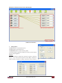
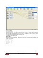
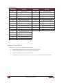
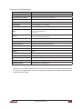
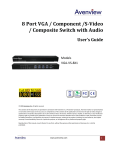
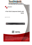
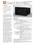
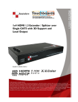
Avenview 5 In 5 Out VGA Matrix Switch with Audio Model #: SW-VGA-5X5 © 2010 Avenview Inc. All rights reserved. The contents of this document are provided in connection with Avenview Inc. (“Avenview”) products. Avenview makes no representations or warranties with respect to the accuracy or completeness of the contents of this publication and reserves the right to make changes to specifications and product descriptions at any time without notice. No license, whether express, implied, or otherwise, to any intellectual property rights is granted by this publication. Except as set forth in Avenview Standard Terms and Conditions of Sale, Avenview assumes no liability whatsoever, and disclaims any express or implied warranty, relating to its products of Avenview Inc. is strictly prohibited. Table of Contents Section 1: Getting Started.......................................................................................................................1 1.1 Important Safeguards...............................................................................................................1 1.2 Safety Instructions....................................................................................................................1 1.3 Regulatory Notices Federal Communications Commission (FCC).............................................2 1.4 Introduction.............................................................................................................................2 1.5 Features....................................................................................................................................2 1.6 Package Contents.....................................................................................................................2 1.7 Before Installation....................................................................................................................3 1.8 Panel Description.....................................................................................................................3 1.9 Channel Control.......................................................................................................................4 Section 2: Installation..............................................................................................................................8 Section 3: Specifications..........................................................................................................................9 Section 1: Getting Started 1.1 Important Safeguards Please read all of these instructions carefully before you use the device. Save this manual for future reference. What the warranty does not cover •Any product, on which the serial number has been defaced, modified or removed. •Damage, deterioration or malfunction resulting from: •Accident, misuse, neglect, fire, water, lightning, or other acts of nature, unauthorized product modification, or failure to follow instructions supplied with the product. •Repair or attempted repair by anyone not authorized by us. •Any damage of the product due to shipment. •Removal or installation of the product. •Causes external to the product, such as electric power fluctuation or failure. •Use of supplies or parts not meeting our specifications. •Normal wear and tear. •Any other causes which does not relate to a product defect. •Removal, installation, and set-up service charges. 1.2 Safety Instructions The SW-VGA-5X5, Avenview 5 in 5 Out VGA Matrix Switch with Audio has been tested for conformance to safety regulations and requirements, and has been certified for international use. However, like all electronic equipments, the SW-VGA-5X5 should be used with care. Please read and follow the safety instructions to protect yourself from possible injury and to minimize the risk of damage to the unit. •Do not dismantle the housing or modify the module. •Dismantling the housing or modifying the module may result in electrical shock or burn. •Refer all servicing to qualified service personnel. •Do not attempt to service this product yourself as opening or removing housing may expose you to dangerous voltage or other hazards •Keep the module away from liquids. •Spillage into the housing may result in fire, electrical shock, or equipment damage. If an object or liquid falls or spills on to the housing, unplug the module immediately. •Have the module checked by a qualified service engineer before using it again. •Do not use liquid or aerosol cleaners to clean this unit. Always unplug the power to the device before cleaning. Avenview www.avenview.com 1 1.3 Regulatory Notices Federal Communications Commission (FCC) This equipment has been tested and found to comply with Part 15 of the FCC rules. These limits are designed to provide reasonable protection against harmful interference in a residential installation. Any changes or modifications made to this equipment may void the user's authority to operate this equipment. 1.4 Introduction This SW-VGA-5X5 is a 5 input 5 output commercial VGA with audio matrix switcher. The SW-VGA-5X5 is one of the world's advanced matrix switchers. It is capable of being controlled though RS-232 via software included or via a third party control system. Switcher is designed to handle any resolution up to 1920x1200 or 1080p without any signal degradation. This device is mainly used in broadcast rooms, multi council-chambers, television teaching rooms, command centers and IT server rooms. 1.5 Features - Power-fail protection, allows switcher to restore previous settings - RS-232 communication control input, allows to control switcher via included advanced control software or third party control system - IR remote control - Inputs: 5 x VGA female15-pin HD, 5 x 1/8'' (3.5mm) mini audio - Outputs: 5 x VGA female 15-pin HD, 5 x 1/8'' (3.5mm) mini audio - Connectors: 15-pin HD (could be used for PC resolutions up to WUXGA - 1920x1200 or HDTV up to 1080p) - Compatible formats: RGB, YPbPr or RGBHV - Rack mountable 1.6 Package Contents Before you start the installation of the converter, please check the package contents. 2 - SW-VGA-5X5 x1 - VGA to component breakout cable x 10 - IR remote control x1 - Power adapter (+5VDC) x1 - 1RU rack-mount ear set x1 - User Guide x1 - Installation CD x1 www.avenview.com Avenview 1.7 Before Installation •Put the product in an even and stable location. If the product falls down or drops, it may cause an injury or malfunction. •Don't place the product in too high temperature (over 50°C), too low temperature (under 0°C) or high humidity. •Use the DC power adapter with correct specifications. If inappropriate power supply is used then it may cause a fire. 1.8 Panel Description FRONT PANEL 1 2 3 4 5 6 7 8 1. Display of the Selected Input Channel 2. Decrease of Input Channels 3. Increase of Input Channels 4. Decrease of Output Channels 5. Increase of Output Channels 6. IR Receiver 7. Power Indicator 8. Display of the Selected Input Channel REAR PANEL 9 10 11 12 9. Audio Inputs 10. Audio Outputs 11. Video Inputs 12. Video Outputs 13. 5V DC Power 14. RS232 Control Port Avenview www.avenview.com 13 14 3 1.9 Channel Control Method A: Front panel push button control 1. Use the “+” or “–“ channel button on output port to select which port to be changed. “+”: change selected output port in ascending order “–“: change selected output port in descending order 2. Push the “+” or “–“ channel button on Input channel to select the VGA input source you want to display on this selected output port in step 1 in sequential order. Once you reach the desired input channel you want to display on this selected output port, leave it and the setting will be effective in a few seconds. Method B: IR remote control Please push one of the INPUT buttons to choose which VGA input source you are going to setup. After that, you can have multiple outputs playing the same content from the selected INPUT 1 — INPUT 5 by pushing the corresponding OUTPUT buttons. The setting will be effective in a couple of seconds. INPUT & OUTPUT MAPPING 4 INPUT 1 VGA input port #1 INPUT 2 VGA input port #2 INPUT 3 VGA input port #3 INPUT 4 VGA input port #4 INPUT 5 VGA input port #5 OUTPUT 1 VGA output port #1 OUTPUT 2 VGA output port #2 OUTPUT 3 VGA output port #3 OUTPUT 4 VGA output port #4 OUTPUT 5 VGA output port #5 www.avenview.com Avenview Method C: Software Control via the RS-232 port VGA input source selection area VGA output port selection area Status indicator Software Control Menu 1. Setting button: Click Get button to read back device ID. Click Set button to write device ID. Click Rename button to open the String Table. In the String Table, assign the captions for each input and output port for easy recognition. Example Rename the Input1 to “Main PC”, Input2 to “Sub PC,” input3 to “PC-3,” … etc., and rename output1 to “Conf. RM1,” output2 to “Main monitor,” output3 to “Lobby,” output4 to “Main projector,” … etc. Avenview www.avenview.com 5 2. Scan button: Serial Port Scan: Click Scan button, the machine will scan the all com port and show them. Select the RS232 serial port connected to the machine. And set device ID 255 is for all device. Only the same device id or 255 can get the command you sent. Click OK. Get the new status from the machine you select. 3. Linkage button: Click Linkage button to read back all status. 4. Open/Close button: Click this button to close or open COM port. 5. Mapping button: Select All Output: Select “set all output”, then select the source on main menu. You can quickly set all output to the same source. Unselect All Output: Release output selection. Select Input1~8 - Output: Select Input channel then select the output port. Example Select input source 1. Then select output port 1 and 2. The video and audio will be sent to port 1 and 2. 6. Fast Select button: Click Fast select button for quick setting Input one Output Port one Input two Output Port two ….. From Fast Select pull down menu: Select Input Num-Output Num Input source #1 Output port #1 Input source #2 Output port #2 ….. Select Input - All Output Send the same source to all output 6 www.avenview.com Avenview 7. Output Port: Pull down menu and select which source to be sent to this output port. One by one setting On main menu screen First select input source. Then select the output ports which you want to send the video and audio from this source. When you select the input source, the source will change to gray. When you select the output port one by one, the selected output port will change to gray. The linking line will change to yellow. Group setting First select output ports one by one. Then select the input source. The selected output ports change the setting at the same time. By using Terminal: Baud rate: 9600 Data length: 8bit Parity check: No Stop bit: 1 Avenview www.avenview.com 7 Command Set: COMMAND ACTION COMMAND ACTION ST System Status VR Firmware Version A1 Output A select Input 1 B1 Output B select Input 1 A2 Output A select Input 2 B2 Output B select Input 2 A3 Output A select Input 3 B3 Output B select Input 3 A4 Output A select Input 4 B4 Output B select Input 4 A5 Output A select Input 5 B5 Output B select Input 5 C1 Output C select Input 1 D1 Output D select Input 1 C2 Output C select Input 2 D2 Output D select Input 2 C3 Output C select Input 3 D3 Output D select Input 3 C4 Output C select Input 4 D4 Output D select Input 4 C5 Output C select Input 5 D5 Output D select Input 5 E1 Output E select Input 1 E2 Output E select Input 2 E3 Output E select Input 3 E4 Output E select Input 4 E5 Output E select Input 5 Section 2: Installation Follow these instructions for installation of SW-VGA-5X5: 1. Connect VGA enable equipments to the outputs of SW-VGA-5X5. 2. Connect the VGA input sources to the inputs of SW-VGA-5X5. 3. Plug power adapter cable into 5V DC power jack. 4. Use IR Remote, RS-232 serial commands, or front panel push button to switch among inputs. 8 www.avenview.com Avenview Section 3: Specifications Item Description Model SW-VGA-5X5 (VGA Matrix Switch) Supported Input / Output VGA / Component / S-video / Composite* Video Bandwidth 400 MHz Supported Resolutions 1080p60, WUXGA (1920x1200@60) & UXGA (1600x1200@60) Transmission HD (720p/1080i) – 65m (210ft) Audio Support Analog Stereo Input 5 x VGA (Component through VGA to Component Cable) 5 x 3.5mm Analog Audio 1 x RS232 Output 5x VGA [component/s-video/composite]* 5 x 3.5mm Analog Stereo Audio VGA Connector HD-15 (15-pin D-sub female) RS232 Connector DE-9 (9 pin D-Sub female) 3.5mm Connector Earphone Jack for Analog Stereo Audio Input Selection IR Remote / Push Button / RS232 Dimensions 1RU – 17.3” x 3.8” x 1.7” (L x W x H) Weight 2.4 lbs Power Supply 5V 4A DC Power Consumption 13 Watts (max) Operating Temperature 0~40°C [32~104°F] Storage Temperature -20~60°C [-4~140°F] Relative Humidity 20~90% RH [no condensation] * Component and composite inputs/outputs can be done by using VGA-to-component breakout cables to connect to the VGA sockets. For S-Video inputs/outputs, please find a VGA-to-S-video adapter to connect to the VGA sockets. Avenview www.avenview.com 9 Avenview Disclaimer While every precaution has been taken in the preparation of this document, Avenview Inc. assumes no liability with respect to the operation or use of Avenview hardware, software or other products and documentation described herein, for any act or omission of Avenview concerning such products or this documentation, for any interruption of service, loss or interruption of business, loss of anticipatory profits, or for punitive, incidental or consequential damages in connection with the furnishing, performance, or use of the Avenview hardware, software, or other products and documentation provided herein. Avenview Inc. reserves the right to make changes without further notice to a product or system described herein to improve reliability, function or design. With respect to Avenview products which this document relates, Avenview disclaims all express or implied warranties regarding such products, including but not limited to, the implied warranties of merchantability, fitness for a particular purpose, and non-infringement. Avenview www.avenview.com Avenview