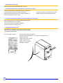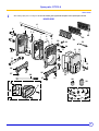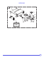
1
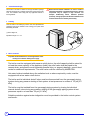
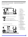
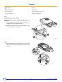
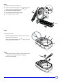
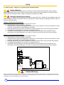
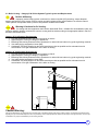
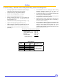
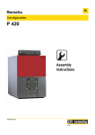
GT 210 A
Oil-Gas Fired Hot Water Boiler
English
02/12/07
Please Read & Save this
Manual for Future
Reference
Assembly, installation and maintenance manual
Warning:
Before putting the boiler into operation read this manual
carefully.
Warning:
The operating manual is part of the documentation that is
delivered to the installation’s operator. Go through the
information in this manual with the owner/operator and
make sure that he or she is familiar with all the necessary
operating instructions.
94863106
Notice:
This manual must be retained for future reference. Improper
installation, adjustment, alteration, service or maintenance can
cause injury, loss of life or property damage. Refer to this
manual. For assistance or additional information consult a
qualified installer, service agency or the gas supplier.
Guideline of Notices
Safety Considerations
Warning:
indicates presence of hazards that can cause, if not
avoided, severe personal injury, death or substantial
property damage.
!
Caution:
indicates presence of hazards that will or can cause, if not
avoided, minor personal injury or property damage.
Notice:
Application comment for optimum use of equipment and
adjustment as well as useful information.
Z
Reference to an other instruction book.
Please observe the following safety instructions.
Read this manual carefully.
Correct installation and adjustment of the burner and the control
panel is a precondition for safe, efficient operation of the gas boiler.
Read this manual and the specifications on the safety label carefully
before attempting to put the burner into operation.
not store or use gasoline or other flammable liquids in
Do
the vicinity of this or any other appliance.
WHAT TO DO IF YOU SMELL GAS:
- Do not try to light any appliance.
- Do not touch any electric switch, do not use any phone in
your building.
- Immediately call your gas supplier from a neighbor’s
phone. Follow the gas supplier’s instructions.
- If you cannot reach your gas supplier, call the Fire
Department.
Observe the following symbols
DANGER
due to explosion of gas.
- Work only on gas components when you have a license to do so.
- Note that the assembly of gas and vent connections, the initial
start-up, the electrical connections, the maintenance and service
can only be performed by a licensed service contractor or
technician.
DANGER
due to electricity.
Installation and service must be performed by a qualified
installer, service agency or the gas supplier.
Warning:
Improper installation, adjustment, and/or operation could
cause carbon monoxide poisoning resulting in injury or
death.
This product must be installed and serviced by a
professional service technician who is experienced and
qualified in hot water boiler installation and gas
combustion.
- Prior to doing any work on the heating system, disconnect all
electrical power to the boiler at the emergency switch.
- It is NOT sufficient to shut off only the boiler control!
!
CAUTION!
SYSTEM DAMAGE
due to improper installation.
- Observe local and state codes as well as common industry
practices during the installation and operation of the heating
appliance.
!
!
Caution: Strict compliance with these instructions is a
precondition for the correct operation of the boiler.
!
IMPORTANT
Service on this boiler should be undertaken only by trained and
skilled personnel.
Keep boiler area clear and free from combustible materials,
gasoline and other flammable vapors and liquids.
Do not place any obstruction in the boiler room that will hinder
the flow of combustion and ventilating air.
Read these instructions carefully before proceeding with the
installation of boiler. Post instructions near boiler for reference
by owner and serviceman.
Maintain instructions in legible condition.
CAUTION!
SYSTEM DAMAGE
due to inadequate cleaning and maintenance.
- A boiler cleaning and maintenance should be performed annually.
Verify complete system operation at the same time.
- Correct the problem immediately to prevent damage to the
system!
!
Caution:
Refer to User’s Manual regarding the carcinogenic hazard of
crystalline silica that may be found during installation, servicing
and removal of this boiler.
"Installation of this equipment must be in accordance to all local and
national codes or authorities having jurisdiction."
[Canadian Installations]
CSA B149 for gas fired boilers & CSA B139 for oil fired boiler
[USA Installations]
NFPA 54/ANSI Z223.1 for gas fired boiler & NFPA 31 for oil fired boilers.
The boiler must be connected to a venting system that will safely
discharge all flue gas to the outside in a safe and effective manner.
Do not use gasoline, crankcase draining, or any other oil containing
gasoline.
The boiler is certified to burn only natural gas, # 2 fuel oil and propane.
Never burn garbage or paper in the unit, and never leave combustible
materials around the boiler.
2
GT 210 A
21/08/06 - 94863106 - 82274096E
Contents
Regulations and guidelines . . . . . . . . . . . . . . . . . . . . . . . . . . . . . . . . . . . . . . . . . . . . . . . . . . . . . . . . . . . . . . . . . . . .4
General . . . . . . . . . . . . . . . . . . . . . . . . . . . . . . . . . . . . . . . . . . . . . . . . . . . . . . . . . . . . . . . . . . . . . . . . . . . . . . . . . . . . .4
1 Uncrating . . . . . . . . . . . . . . . . . . . . . . . . . . . . . . . . . . . . . . . . . . . . . . . . . . . . . . . . . . . . . . . . . . . . . . . . . . . . . . . . . . . . . . . . . . . . . . . .4
2 Technical specifications of boilers . . . . . . . . . . . . . . . . . . . . . . . . . . . . . . . . . . . . . . . . . . . . . . . . . . . . . . . . . . . . . . . . . . . . . . . . . . . . .5
3 Main Dimensions . . . . . . . . . . . . . . . . . . . . . . . . . . . . . . . . . . . . . . . . . . . . . . . . . . . . . . . . . . . . . . . . . . . . . . . . . . . . . . . . . . . . . . . . . .6
Installation . . . . . . . . . . . . . . . . . . . . . . . . . . . . . . . . . . . . . . . . . . . . . . . . . . . . . . . . . . . . . . . . . . . . . . . . . . . . . . . . . .7
1
2
3
4
Location . . . . . . . . . . . . . . . . . . . . . . . . . . . . . . . . . . . . . . . . . . . . . . . . . . . . . . . . . . . . . . . . . . . . . . . . . . . . . . . . . . . . . . . . . . . . . . . . .7
Aeration . . . . . . . . . . . . . . . . . . . . . . . . . . . . . . . . . . . . . . . . . . . . . . . . . . . . . . . . . . . . . . . . . . . . . . . . . . . . . . . . . . . . . . . . . . . . . . . . .8
Levelling . . . . . . . . . . . . . . . . . . . . . . . . . . . . . . . . . . . . . . . . . . . . . . . . . . . . . . . . . . . . . . . . . . . . . . . . . . . . . . . . . . . . . . . . . . . . . . . . .8
Water connection . . . . . . . . . . . . . . . . . . . . . . . . . . . . . . . . . . . . . . . . . . . . . . . . . . . . . . . . . . . . . . . . . . . . . . . . . . . . . . . . . . . . . . . . . .8
Assembly . . . . . . . . . . . . . . . . . . . . . . . . . . . . . . . . . . . . . . . . . . . . . . . . . . . . . . . . . . . . . . . . . . . . . . . . . . . . . . . . . . .9
Chimney connection . . . . . . . . . . . . . . . . . . . . . . . . . . . . . . . . . . . . . . . . . . . . . . . . . . . . . . . . . . . . . . . . . . . . . . . . .24
1 Flue size . . . . . . . . . . . . . . . . . . . . . . . . . . . . . . . . . . . . . . . . . . . . . . . . . . . . . . . . . . . . . . . . . . . . . . . . . . . . . . . . . . . . . . . . . . . . . . . .24
2 Connecting to the flue . . . . . . . . . . . . . . . . . . . . . . . . . . . . . . . . . . . . . . . . . . . . . . . . . . . . . . . . . . . . . . . . . . . . . . . . . . . . . . . . . . . . .24
Connecting the burner . . . . . . . . . . . . . . . . . . . . . . . . . . . . . . . . . . . . . . . . . . . . . . . . . . . . . . . . . . . . . . . . . . . . . . .24
Electrical connections. . . . . . . . . . . . . . . . . . . . . . . . . . . . . . . . . . . . . . . . . . . . . . . . . . . . . . . . . . . . . . . . . . . . . . . .25
Maintenance . . . . . . . . . . . . . . . . . . . . . . . . . . . . . . . . . . . . . . . . . . . . . . . . . . . . . . . . . . . . . . . . . . . . . . . . . . . . . . . .25
1
2
3
4
5
Boiler . . . . . . . . . . . . . . . . . . . . . . . . . . . . . . . . . . . . . . . . . . . . . . . . . . . . . . . . . . . . . . . . . . . . . . . . . . . . . . . . . . . . . . . . . . . . . . . . . .25
Domestic hot water (GT 2100) . . . . . . . . . . . . . . . . . . . . . . . . . . . . . . . . . . . . . . . . . . . . . . . . . . . . . . . . . . . . . . . . . . . . . . . . . . . . . . .26
Precautions required in the case of long boiler stops (one or more years) . . . . . . . . . . . . . . . . . . . . . . . . . . . . . . . . . . . . . . . . . . . . .26
Precautions required if the heating is stopped when there is a risk of freezing . . . . . . . . . . . . . . . . . . . . . . . . . . . . . . . . . . . . . . . . . .26
Identification plate . . . . . . . . . . . . . . . . . . . . . . . . . . . . . . . . . . . . . . . . . . . . . . . . . . . . . . . . . . . . . . . . . . . . . . . . . . . . . . . . . . . . . . . .26
Spare parts - GT 210 A . . . . . . . . . . . . . . . . . . . . . . . . . . . . . . . . . . . . . . . . . . . . . . . . . . . . . . . . . . . . . . . . . . . . . . .27
21/08/06 - 94863106 - 82274096E
GT 210 A
3
Regulations and guidelines
The installation must conform to the requirements of the authority
having jurisdiction or, in the absence of such requirements, to the
National Fuel Gas Code, ANSI Z 223.1 / NFPA 54. In Canada,
installation must be in accordance with the requirements of CAN/
CGA B149.1 or 2 Installation Code for Gas Burning Appliances and
Equipment. Where required by the authority having jurisdiction, the
installation must conform to the Standard for Controls and Safety
Devices for Automatically Fired Boilers, ANSI/ASME CSD-1.
Install CO detectors per local regulations. Boiler requires yearly
maintenance, see "Connecting the burner", page 24.
Only a qualified installing contractor may carry out the installation, the
initial start-up, the connection for fixed gas and vent gas, and
conversion to another type of gas. The hot water distribution system
must comply with the applicable codes and regulations. When
replacing an existing boiler, it is important to check the entire hot
water distribution system to insure safe operation. Maintenance and
cleaning must be carried out at least once a year by a trained service
technician. The entire installation must be tested for proper
operation. Any defects detected must be fixed immediately.
General
The boilers of the GT 210 A range are automatic independent hotwater boilers designed for connecting to a flue which require a sepa-
rate fuel oil or gas burner.
1 Uncrating
Upon arrival, check shipment to ensure all parts have been shipped.
Inspect all items for delivery damage. Report all damage and shortages to the delivery carrier. Report any damage and shortages to
the Distributor.
Boiler
GT 214 A
GT 215 A
GT 216 A
GT 217 A
GT 218 A
- front section
1
1
1
1
1
- intermediate section
2
3
4
5
6
- rear section
1
1
1
1
1
- set of assembly rods
-
-
1
1
1
- accessory package
DR 64
DR 65
DR 66
DR 67
DR 68
DR 84
DR 85
DR 86
DR 87
DR 88
DR 90
DR 90
DR 90
DR 90
DR 90
• Unassembled boiler body
88
00
N0
72
• Assembled boiler body
with accessories
Control panel
Casing
DR 74
4
DR 75
DR 76
GT 210 A
DR 77
DR 78
21/08/06 - 94863106 - 82274096E
2 Technical specifications of boilers
Item
Unit
GT 214 A
GT 215 A
MBH
173
224
Firing Sequence
[CSA] - Gas Input
[CSA] - # 2 Fuel Oil Input
GT 217 A
GT 218 A
Consult Burner Technical Data
274
324
361
kW
50.7
65.7
80.3
95.0
105.8
US GPH
1.20
1.55
1.90
2.25
2.50
MBH
147
190
233
276
306
kW
43.1
55.7
68.3
80.8
89.8
[NET] - Output [Gas-Oil]
MBH
128
165
203
240
266
Cast Iron sections
#
4
5
6
7
8
[CSA] - Output [Gas-Oil]
Flue-way baffles
Water capacity
#
3
2
2
2
2
US Gal
9.5
11.4
13.2
15.1
16.9
Liter
36
43
50
57
64
18° F
Ft. H2O
0.82
1.34
1.99
2.77
3.4
27° F
Ft. H2O
0.365
0.596
0.887
1.23
1.51
36° F
Ft. H2O
0.204
0.335
0.498
0.693
0.85
Diameter
[equivalent]
Inch
12.17
mm
309
Water resistance
[∆t = °F]
Combustion chamber
Dimensions
Depth
Volume
MAWP [Water]
Min. Safety Relief Capacity
DR 90 Panel
GT 216 A
Inch
17.6
22.6
27.6
32.6
37.6
mm
446
573
700
827
954
ft3
1.1653
1.4831
1.8009
2.1188
2.4366
m3
0.033
0.042
0.051
0.060
0.069
PSI
MBH
ASME IV Rating Class 30 - (60 PSI) [See Canadian Provincial CRN approvals]
147
190
233
Electrical connection
V/P/H
120/1/60
Max. Water Temp. Safety Limit
[MR]
°F
230
°C
110
Operating Water Temperature
Range
°F
86 - 185
°C
30 - 85
Chamber resistance
276
306
Inch w.c.
0.08 - 0.16
0.20 - 0.24
0.08 - 0.24
0.16 - 0.24
0.24 - 0.32
mbar
0.2 - 0.4
0.5 - 0.6
0.2 - 0.6
0.4 - 0.6
0.6 - 0.8
7
7
Gas-Vent Category
#
Boiler Vent connection
Inch
6
6
7
lb
481
567
655
741
827
kg
218
257
297
336
375
Weight (dry)
I, II - III or IV
- CSA - MBH Output based on Thermal Efficiency Test According to
ANSI Z21.13a/CSA 4.9a-2005
- [NET] MBH Output Factor 1.15, Allowance for Piping and Pickup
Losses
- Chamber Resistance Based on Neutral Chimney-Vent Pressure
- Gas Vent Category Based on Several Factors [CO2 content, Vent
Pressure & Net-Flue Gas Temp]
- Approved for Direct-Vent, Use Only Approved Venting as Listed
- Natural Draft Applications, Approved for Type L vent [Gas-Oil] or
Type B Vent [Gas Only]
- Conversion Btu to kW = 3,412 Btu per kW
- All Models are Design Certified & Eligible to Bear Approval Marking
as Shown.
- All Models Certified to Fire; # 2 oil, Natural & Propane Gases.
Consult factory for Available Burners.
- All Models Comply and Certified in Accordance to the latest
Canadian & US standards
21/08/06 - 94863106 - 82274096E
- To Obtain Current IBR Ratings, consult their publications and
website.
GT 210 A
5
3 Main Dimensions
4Ø M8 tapped outlets
on 515/16 Ø
43markings on
6 /4Ø
27/8
heating
outlet
DØ
Tapping
1/4"
2911/16
7
7
77/16
/16
/16
14
/8
/16
113/16
1
1
4
4
/2
=
51/8
9
5 /16
/2
=
Tapping
3/4"
5
13
BØ
flue gas
nozzle
heating
return
DØ
3
2" (1)
97/16
14
A
87/16
47/16 Ø drilling
51/8 Ø cut-on
387/8
47/16
15
/16
45°
22
23
1
C
61/2
=
63/16
=
3/4" tapped
draining tube
optional
delivered burner
3
(1) Adjustable feet: basic height 2" with 1
6
/16
Rp : Tapped
R : Threaded
to 21/2 adjustment range.
A
B
C
ØD
GT 214 A
235/16
6
1611/16
R 1 1/4
GT 215 A
285/16
6
2111/16
R 1 1/4
GT 216 A
335/16
7
2611/16
R 1 1/2
GT 217 A
385/16
7
3111/16
R 1 1/2
GT 218 A
435/16
7
3611/16
R 1 1/2
GT 210 A
21/08/06 - 94863106 - 82274096E
Installation
1 Location
Sufficient space shall be left clear around the boiler for servicing and clearances to combustibles
The values provided in the drawings are in inches below are the minimum
recommended dimensions for providing easy access around the
boiler. Dimension 'X' consult burner + 24 inches for servicing.
387/8
L1
GT 214 A
2911/16
GT 215 A
3411/16
GT 216 A
3911/16
GT 217 A
4411/16
GT 218 A
4911/16
Boiler must not be
installed on a
combustible flooring or
pad, do not install on
carpet.
19 11
/16
6
11 /1
L1
19
22
6
11 /1
X
The two 3/4” or 1” pipes are not supplied.
8227N058A
To facilitate boiler installation, a handling tool (package BG 45, no.
8218-7723) may be used as shown opposite to move the heating
elements or place the boiler on the calorifier.
19
3/4"-1"
21/08/06 - 94863106 - 82274096E
GT 210 A
7
2
Combustion Air Supply
The location of air inlets in relation to the high ventilation openings
shall ensure that the air is renewed in the entire volume of the boiler
room. The ventilation shall comply with any applicable national or
local regulations.
note that boilers installed in or close to rooms in
Please
which the atmosphere is polluted with chlorine or fluorine
compounds may be subject to high corrosion. For
example: hairdressing salons, industrial premises
(solvents), cooling equipment etc. Boilers installed in such
locations shall not be covered by the warranty.
3 Levelling
Level as shown in the drawing by means of the four adjustable feet
(supplied in the bag of fasteners of the casing) put in place while
assembling the boiler.
(1) basic height 13/8,
adjustment range: 13/8 - 21/2
(1)
13/8
4 Water connection
Important recommendations for connecting the boiler to the
heating circuit and the drinking water supply
The boiler must be equipped with pressure relief device, the relief capacity shall be sized for
at least the same capacity of the appliance [mbh], the relief valve shall be piped to the
nearest drain, and piped to avoid potential personal injury or property damage, consult local
codes for additional requirements. The relief valve must be certified by AMSE/CRN.
Hot water boilers installed above the radiation level or where required by code, must be
equipped with a low water cutoff device.
The boiler and its individual shutoff valve must be disconnected from the gas supply piping
system during any pressure testing of that system at test pressures in excess of 1/2 psi [3.5
kPa]
The boiler must be isolated from the gas supply piping system by closing its individual
manual shutoff valve during any pressure testing of the gas supply piping system at test
pressures equal to or less than 1/2 psi [3.5 kPa]
Suitable protection against water indigestion must be provided to the boiler control system
and burner.
8
GT 210 A
21/08/06 - 94863106 - 82274096E
represented, but it is finally up to the fitter to decide which control and safety systems are required for each specific situation. In any case, comply with applicable codes
of practice and local or national regulations.
The following examples do not intend to cover all the
possible cases of installation. They are only provided
to draw attention to the basic rules which must be respected. Some control and safety devices have been
4.3 Examples of installation
Boiler must not be installed on a combustible
flooring or pad, do not install on carpet.
51
7
21
9
9
9
11
9
230V
50Hz
52
27
26
9
9
32
9
31
9
4 3
27
7
24
30
33
25
2
28
27
16
17
29 9
➤
22 1
9 50 18
8227N045A
Standard DR 90 control panel heating only
6
5
7
3
9
4
8
1
2
3
4
7
9
10
11
16
17
18
21
22
23
TEST STB
30
AUTO
°C
24
6,5 AT
20
1,5 2 2,5
1,0
3
0,5
3,5
14
Option - MB1 A for DHW production
1 2 3 4 5 6 7
14
1...7
20
8
-
+
Prog
50
60
1
2
R
20
°C
332 DB
80
Option - SV-matic 321 DHW & outdoor sensor
Option - SV-matic 331 DHW & 3-way valve - Outdoor sensor
20
1,5 2 2,5
1,0
3
0,5
3,5
14
1,5 2 2,5
1,0
3
0,5
3,5
26
1 2 3 4 5 6 7
14
1...7
20
8
-
+
Prog
50
60
40
1
2
30
R
20
°C
25
26
1,5 2 2,5
1,0
3
0,5
3,5
40
30
332 DB
80
51
23
7
9
9
9
11
230V
9
50Hz
10
4 3
26
72
9
32
9
31
9
72
27
M
27
7
9
24
33
22
22 1
2
17
27
28
29
30
31
32
33
44
50
51
52
65
2. Installation with 1 circuit with mixing valve
21
26
Heating flow
Heating return
3-bar safety valve
Pressure gauge
Automatic bleeder valve
Valve
3-way mixing valve
Heating pump
Expansion vessel
Draining tap
Heating circuit filling valve
Outside temperature sensor
Boiler sensor
Mixing valve outlet
temperature sensor
Primary input of dhw
calorifier exchanger
Primary output of dhw
calorifier exchanger
Domestic hot water
filling pump
Nonreturn valve
Domestic cold water inlet
Pressure reducer
Sealed safety device
calibrated to 7 bar
Independent dhw tank
(Optional) dhw looping pump
Dhw temperature sensor
Limiting thermostat
Disconnector
Thermostatic valve
Differential valve
Heating circuit which may be
at a low temperature
(radiators or floor heating)
Hydraulic bypass required
with floor heating systems
25
16
27
30
29 9
28
9 50 18
8227N047A
*
9
Assembly
Tools required :
- hammer
- Philips head screwdriver
- silicone glue
- wide flat screwdriver
- JDTE Plus ASME assembly tool
- 13 and 17 mm wrench
- simplified assembly tool
Step 1
Preparing the front and rear sections
Installing the height converter and the adjustable feet on the
rear section
`Fix the adjustable feet (supplied in the bag containing the
casing fasteners) onto the height converter.
`Place the rear section on the floor and fix the height converter
(2 HM 10 x 25 screws, 17 mm wrench).
17
1
2
8227N014A
Step 2
`Fix the adjustable feet onto the height converter, place the front
section on the floor (with the groove facing up) and fix the height
converter.
4
2
3
1
8227N019
10
GT 210 A
21/08/06 - 94863106 - 82274096E
Step 3
1. Support the section with a wooden block.
2. Place a block with a height of approx. 515/16 (depending upon the
number of sections, the length varies from 125/8 - 321/4).
3. Clean the bores and nipples with thinner.
4
1
5
4. Coat them with the coating material supplied.
5. Push in the two nipples moderately.
3
515/16
2
Step 4
Assembling the sections
`Place the intermediate sections on the floor, groove upwards.
`Prepare the silicone cartridge.
`Put a drop of silicone at about every 77/8 of the groove of the
intermediate and front sections.
6A
01
7N
2
82
Step 5
`Working from point A as shown above, insert the silicone braid
into the groove of the intermediate and front sections.
`Cut it to the correct length.
2
A
1
8227N017A
11
Step 6
`Place the intermediate element on the wooden block.
`Fit the connections of the intermediate element into the nipples
on the rear.
`Hammer in with the help of a small wooden block.
`Proceed likewise for the other intermediate sections.
Step 7
`Complete the assembly with the front section.
`Clean any extra silicone
`Remove the wooden block.
`Remove the assembly tool.
`Put the two threaded rods in place without removing the
assembly tool and fasten with the four H8 flanged nuts supplied.
0mm
4
2
4
4
2
1
3
4
B
22
N0
27
82
7
12
21/08/06 - 94863106 - 82274096E
GT 210 A
GT 210 A
21/08/06 - 94863106 - 82274096E
Hydraulic test [Required for field assembled assemblies]
1
1
1
After assembling the boiler body, the installer must carry out a water tightness test at a pressure equal to 1.5
times the operating pressure (that is 5,2 bar minimum)
for 10 minutes at least. The test must be done at room
temperature.
Ensure that all the air in the boiler is
vented to avoid any bursting of the body.
4
2
5
5,2
3
0
bar
82
27
N1
71
Maintain pressure for at least 10 minutes.
Any drop in pressure indicates a leakage in the boiler body.
After the tightness test, drain the boiler and remove
all the parts used for the test.
13
Step 8
Assembling the outlet, return and draining tubes
`Coat the threaded and tapped connections of the sections,
tubes, plugs and thimble tubes with pipe dope (not supplied).
`Screw the threaded plug with the thimble tube in the upper
connection and the other in the lower connection.
`Screw the 2 outlet and return tubes and the draining tube onto
the rear section.
`On the front, install the two M10 pins in the holes designed for
that purpose.
The assembled body shall be tested with a water pressure of 90
psi (1,5 maxi working pressure).
1
1
- for 4 and 5 section boilers use 1”1/4 NPT flow pipe.
Place the smaller threaded side to the outside.
- for 6 to 8 sections boilers use 1”1/2 NPT flow pipe. Place the
threaded side with the yellow marking to the outside.
Step 9
Assembling the door with right-hand opening
1 Put the lower hinge in place, press it against the front section and
fix it with an HM 10x50 screw + wide CL 10-20 tapered washer (17
mm wrench).
2
1
8227N025B
2 Assemble the other HM 10x50 hinge and wide CL 10-20 tapered
washer.
17
14
GT 210 A
21/08/06 - 94863106 - 82274096E
Step 10
3 Mount the upper hinge (1 H 10x50 screw).
4
- Mount the H 10x20 adjusting screw on the upper hinge.
3
2
8227N026A
Step 11
Adjust the upper hinge to adjust the door:
• unfasten screw A,
• adjust screw B so that the door is positioned correctly
• fasten screw A.
B
17
A
8227N027B
21/08/06 - 94863106 - 82274096E
GT 210 A
15
Step 12
Assembling the door with left-hand opening
3
`Proceed similarly, with the hinges on the left-hand side.
4
2
6
1
17
5
8227N057B
Step 13
Installing the convection accelerators
`Open the door.
`Place the convection accelerators in the flues passage.
25
GT214A: DR64 box
1 x 8227-0017 item 23
1 x 8227-0012 item 24
1 x 8227-0019 item 25
GT215A: DR65 box
1 x 8227-0017 item 23
1 x 8227-0019 item 25
GT216A: DR66 box
23
1 x 8227-0011 item 23
1 x 8227-0018 item 25
GT217A: DR67 box
24
1 x 8227-0011 item 23
1 x 8227-0018 item 25
GT218A: DR68 box
8227N028B
1 x 8227-0017 item 23
1 x 8227-0019item 25
16
GT 210 A
21/08/06 - 94863106 - 82274096E
Step 14
`Close the door with the two special nuts (17 mm wrench).
822
7N0
29A
17
Step 15
Assembling the flue gas nozzle
`Screw 2 M8 pins in the rear section.
assembled boiler shall be subjected to a hydrostatic
The
test pressure not less than 1 1/2 times the maximum
allowable working pressure : 60 x 1.5 = 90 psi (with a
maximum of 99 psi) and during more than 10 minutes.
1
8227N030A
21/08/06 - 94863106 - 82274096E
GT 210 A
17
Step 16
`Assemble the flue gas nozzle onto the pins and fix with two
flanged nuts. Do not over tighten.
2
8227N032A
Step 17
Assembling the control panel
1. Place the control panel on the boiler body.
3. Push it completly to mounting tabs.
2. Position it on the body assembly rod.
4. Secure it to the front with two M8 screws + serrated washers
screwed into the cast iron.
1
4
3
2
822
7N
18
143
GT 210 A
21/08/06 - 94863106 - 82274096E
Step 18
Installing the bulbs
1 Put the bulbs in place in the thimble tubes, and pass the wires
under the control panel
3 Secure the crossbar to the rear section on the outside of the ears
with two M8 screw and 2 serrated washers.
2 Open the casing package and take out the rear crossbar.
a
1
b
c
3
Step 19
Positioning the insulating material
(black fabric facing downwards)
21/08/06 - 94863106 - 82274096E
GT 210 A
19
Step 20
Installing the insulating material
`Place the insulating material around the body and fix it with two
straps.
`Put one strap on the front, underneath the control panel and the
other at the middle of the remaining part.
Step 21
`Place the two lower side pieces (with the round hole towards the
front and the oblong hole towards the back of the boiler).
`Install :
• to the front with a screw, serrated washer and nut,
• to the rear with a screw, LL washer and nut.
`Screw the screws tightly into the notch of the front height
converters.
20
GT 210 A
21/08/06 - 94863106 - 82274096E
Step 22
Assembling the side panels
`Insert the side panels from the bottom into the notches on the
lower side pieces.
`Put the side panels in contact with the upper rear cross bar.
`Lift the panels up slightly and fit them in.
`Install them to the front of the control panel with two tapping
screws and serrated washers.
`Tighten the screws of the rear crossbar.
822
7N1
48
Step 23
Assembling the lower front panel
`To mount the lower front panel, proceed as follows:
1. Assemble the two tapping screws and serrated washers on the
left and right-hand side panels.
2. Slide lower front panel 2 onto the two tapping screws and
serrated washers.
3. Install two tapping screws and serrated washers on the lower part
and tighten the four screws.
1
2
3
1
3
21/08/06 - 94863106 - 82274096E
GT 210 A
21
Step 24
Installing the lower front insulating material
`Install the insulation of the lower front panel with the black fabric
facing upwards.
1
2
3
Step 25
Installing the rear insulating material
1. Mount the lower and upper rear insulating material, with the top
folded in towards the boiler at a 90° angle.
2. Mount the rear plate (8 tapping screws and serrated washers).
2
1
2
3
3
1
22
GT 210 A
8227N040A
1
21/08/06 - 94863106 - 82274096E
Step 26
`If the boiler is connected to the installation, cut the panel with
cutting pliers along the cut-outs.
`If required, assemble the lower part once again to conceal the
cut edges.
`First assemble the lower part with four tapping screws and
serrated washers.
`Install the upper part with four tapping screws and serrated
washers.
`Then clip on the upper part.
5
1
3
1
8227N041A
4
2
Step 27
electrical connections shall be performed by a
The
qualified professional (see the instructions supplied with
Electrical connections:
the control panel).
Step 28
`Assemble the cover, placing it on studs A located on the front
and rear of the left and right-hand side panels.
`Install with four tapping screws and washers.
A
1
1
2
3
2
1
N042A
3
21/08/06 - 94863106 - 82274096E
GT 210 A
23
Step 29
Assembling the insulated furnace door panel
`Install with the three black screws with large heads provided for
that purpose.
1
2
3
1
3
Step 30
Assembling the front panel
`Put notches A on studs B of the lower front panel.
`Push the panel to fit it in.
`Position point C in the centring groove of the side panel.
3
C
044
B
A
822
7N
C
B
B
1
B
C
2
24
GT 210 A
21/08/06 - 94863106 - 82274096E
Step 31
Installation of supply manifold, ports for relief valve 3/4" & P/T
Gauge 1/4" NPT.
- 4/5 sections 1” 1/4
- 6 to 8 sections 1” 1/2
A: Can be mounted on the left or the right hand side.
A
Step 32
Glue the identification plate (supplied in the instructions bag) on the
casing (on the left or right-hand side) in an easily accessible location.
(1) 05 = 2005,
06 = 2006,...
...
year (1)
week
XX
XX
Date of manufacture
Unit serial no.
FLEXIBLE EUTECTIC BOILERS LTD
36 Eleonor Street P.O. Box 1763 NOK 1 NO MITCHEL Ontario
Tel. + 1 519 340 8200 Fax: + 1 519 340 8404
1
60 psi
230 °F
186
46
Stat
eR
740-42 oute
2
0-3 3 Norh.
989
t
- Fa Circl
e
x:
740 vlli e,O
-420- hio
9262 43113
2
3
1
Type of boiler
82
3
27
N1
41
C
installation is not complete unless the nameplate is attached
Thehere.
21/08/06 - 94863106 - 82274096E
GT 210 A
25
Chimney connection
1 Venting the boiler
The boiler must be connected to a venting system that will safely and effectively discharge all flue gases to the outside in an effective
manner.
Do not Co-Vent a Direct Vent or Sidewall vent system boiler, these venting options are specifically designed for single boiler venting,
follow all local and national codes. The sidewall or direct vent termination must be installed in a location which avoid accumulation of
snow or debris that could block the vent terminal. Consult local codes regarding other requirements for the location and installation of
the vent terminal.
Co-Venting with other appliances, must be sized and installed according to CSA B149 & ANSI Z223.1, Any improper operation of
venting system must be corrected and resized according to the tables in part II of national fuel code Z223.1 & CAN CSA B149
installation codes.
2 Connecting the Venting to the Boiler
Consult local and national codes regarding the sizing of the boiler breeching and chimney venting. See venting section of manual regarding
typical venting systems and requirements.
Connecting the burner
the position of the head of the burner in relation
Important:
to the door insulating material must be as shown opposite,
particularly if the burner is not a De Dietrich burner.
Note:
Refer to the instructions supplied with the burner for information
relating to the connections, adjustment, commissioning and
maintenance of the burner.
(1) See burner instructions as supplied
Consult the documentation of the boiler control and the burner documentation as
supplied regarding setup, wiring and startup.
Do not attempt to start the burner, until all service and clean-out doors are closed and
venting is properly connected to the boiler.
Consult the burner documentation regarding the required maintenance required for
the burner, filters and nozzle.
The entire system should be cleaned and check at least once each heating season.
The fuel tank and supply lines to the burner must be installed
according all applicable National and local codes
(1)
47/16 Ø drilling (3)
51/4 Ø cut-out
12"
4 M8 Ø holes on
515/16 Ø
4 markings on 611/16 Ø
143/16
43/8
26
GT 210 A
21/08/06 - 94863106 - 82274096E
Venting
3. Boiler Venting & Chimney General
Caution & Warning:
It is advised and recommended that the heating contractor-professional apply vent materials that are approved and agency listed.
Installation of any venting must follow all local codes in conjunction with vent manufacturer instructions and appliance manufacturer
instructions.
All De Dietrich GT series oil-gas fired cast iron boilers are high performance boilers that could operate under all 4 vent
categories as established by ANSI Z21.13/CSA 4.9 Standard. To assist with application where the vent category is
unknown a graph below has been provided to assist you in determining the vent category and what venting materials
would be acceptable. Although the gas vent categories were developed specifically for gas fired appliances, using this
information is helpful for oil fired boilers. It is very important the venting be selected according to the conditions that the
boiler will operate under, minimum and maximum firing conditions of the boiler must be respected. The venting installed
must comply and be certified to all applicable codes and standards for each jurisdiction.
Gas-Vent Category [4] Definitions:
Cat. I
A Boiler, which operates with a non-positive vent (breech) pressure
and flue gas temperatures which avoids excessive condensation
production in the chamber and venting.
Cat. III
A Boiler, which operates with a positive vent (breech) pressure and
flue gas temperatures which avoids excessive condensation
production in the chamber and venting.
Cat. II
A Boiler, which operates with a non-positive vent (breech) pressure
and flue gas temperatures produce condensation production in the
chamber and venting.
Cat. IV
A Boiler, which operates with a positive vent (breech) pressure and
flue gas temperatures produces condensation production in the
chamber and venting.
Chart A
Chart created by Craig Holdforth
Gas-Fired Appliance Vent Categorization
[According to ANSI Z21.13/CSA 4.9 Gas Boiler Standard]
Carbon Dioxide [CO2] Content %
7
8
9
10
11
12
11
10
9
8
500
456
6
260
Category III
Typical Vent Types
[BH, AL294C®, 304-316L SS]
Category I
Typical Vent Types [A,B,C & L]
412
Chimney-Vent Flue Gas Temperature °F
(Net, Minus Room Temperature)
7
236
211
368
187
324
162
280
138
236
113
192
89
148
Category II
Typical Vent Types
[BH, AL294C®, 304-316L SS]
Category IV
Typical Vent Types
[BH, AL294C®, 304-316L SS]
104
Chimney-Vent Flue Gas Temperature °C
(Net, Minus Room Temperature)
6
64
40
60
15
Negative
Chimney-Vent Pressure
[Inches w.c.]
Positive
27
Venting
3.1 Boiler Venting – Category I & II Typical Layouts and Requirements.
Caution & Warning:
Improperly sealed venting system could result in carbon monoxide [CO] poisoning; ensure adequate
support and fastening of the system. Ensure venting can safely exhaust all flue gases outside in an effective manner.
These systems must operate under a negative vent pressure condition that is stable.
Warning & Cautions for Co-Venting:
Co-venting with other appliances shall conform latest ANSI Z223.1 & CAN/CGA 149 installation codes, any
improper operation shall be corrected, the common venting shall be sized according to the appropriate tables in Part II of
the above mentioned codes.
Category I Vent Systems Requirements:
1. Flue gas temperatures above the green line shown in chart A.
2. Approved type of venting for category I appliances.
3. A barometric draft control maybe employed as required, but is not necessary for correct boiler operation. Consult
a chimney-vent specialist for correct application and usage.
4. Breeching and chimney vent sized in accordance to local and national codes or by good engineering methods.
5. Vent safety device equipped on the venting or as equipped on burner.
6. Condensate TEE fitting supplied on the boiler breeching as close as possible and be orientated to avoid
accumulation of flue gas condensation in the boiler or venting is also used to determine flue gas emissions.
Category II Vent Systems Requirements:
1. Flue gas temperatures below the green line shown in chart A.
2. Approved type of venting for category II appliances.
3. A barometric draft control maybe employed as required, but is not necessary for correct boiler operation. Consult
a chimney-vent specialist for correct application and usage.
4. Breeching and chimney vent sized in accordance to local and national codes or by good engineering methods.
5. Vent safety device equipped on the venting or as equipped on burner.
6. Condensate TEE fitting supplied on the boiler breeching as close as possible and be orientated to avoid
accumulation of flue gas condensation in the boiler or venting is also used to determine flue gas emissions.
Caution-Warning:
Flue gas condensation is very aggressive and corrosive which could lead to failure of the venting system or drains, consult local and national codes
regarding flue gas condensation disposal. The P-trap assembly must be properly filled with water to avoid escape of flue gas emissions. The flue gas
condensation may require neutralization prior to entering the drain.
28
GT 210 A
21/08/06 - 94863106 - 82274096E
3.2 Boiler Venting – Category III & IV Vent Systems Typical Layouts and Requirements.
Caution & Warning:
Improperly sealed venting system could result in carbon monoxide [CO] poisoning; ensure adequate
support and fastening of the system. Ensure venting can safely exhaust all flue gases outside in an effective manner.
These systems must operate under a positive vent pressure condition that is stable.
Warning & Cautions for Co-Venting:
Co-venting with other appliances shall conform latest ANSI Z223.1 & CAN/CGA 149 installation codes, any
improper operation shall be corrected, the common venting shall be sized according to the appropriate tables in Part II of
the above mentioned codes.
Category III Vent Systems Requirements:
1. Flue gas temperatures above the green line shown in chart A.
2. Approved type of venting for category III appliances
3. Breeching and chimney diameter sized in accordance to national & local codes or by good engineering methods.
4. Vent safety device equipped on burner [MR]
5. Condensate TEE fitting supplied on the boiler breeching as close as possible and be orientated to avoid
accumulation of flue gas condensation in the boiler or venting.
Category IV Vent Systems Requirements:
1. Flue gas temperatures below the green line shown in chart A.
2. Approved type of venting for category IV appliances
3. Breeching and chimney diameter sized in accordance to national & local codes or by good engineering methods.
4. Vent safety device equipped on burner [MR]
5. Condensate TEE fitting supplied on the boiler breeching as close as possible and be orientated to avoid
accumulation of flue gas condensation in the boiler or venting.
Caution-Warning:
Flue gas condensation is very aggressive and corrosive which could lead to failure of the venting system or drains, consult local and national codes
regarding flue gas condensation disposal. The P-trap assembly must be properly filled with water to avoid escape of flue gas emissions. The flue gas
condensation may require neutralization prior to entering the drain.
29
Venting
3.3 Boiler Venting – Side-Wall or Direct Vent Systems Typical Layouts and Requirements.
Caution & Warning:
Improperly sealed venting system could result in carbon monoxide [CO] poisoning; ensure adequate support
and fastening of the system. Ensure venting can safely exhaust all flue gases outside in an effective manner. These
systems must operate under a positive vent pressure condition that is stable. Do not Co-Vent with any other appliance,
the venting system was designed for single appliance venting only.
Side-wall & Direct Vent Systems:
These systems do not fall under any of the gas vent categories, these systems are pre-engineered. These applications of
this venting system must be followed exactly, for safe, efficient and trouble free operation.
System Requirements:
1. Venting sized accordance to direct vent table
2. Type “BH” [AL294C®] vent material
3. Condensate TEE fitting supplied on the boiler breeching as close as possible and be orientated to avoid
accumulation of flue gas condensation in the boiler or venting is also used for determining flue gas emissions.
4. Vent termination TEE
5. Vent safety device equipped on burner [MR]
Vent Termination Locations & Warning – See Section 5.5
Caution-Warning:
Flue gas condensation is very aggressive and corrosive which could lead to failure of the venting system or drains, consult local and national codes
regarding flue gas condensation disposal. The P-trap assembly must be properly filled with water to avoid escape of flue gas emissions. The flue gas
condensation may require neutralization prior to entering the drain.
30
GT 210 A
21/08/06 - 94863106 - 82274096E
Venting
5.4 Boiler Venting – Side-wall or Direct Vent Systems Sizing Tables & Vent Safety Device
•
Vent termination must be a TEE type, follow warning
regarding termination locations. Do not include the
termination TEE length in the vent length calculation.
•
Venting shall be sloped, so any condensation developed will
drain through the condensate TEE fitting
Minimum vent length [equivalent] 5 ft. [1.5m]
•
Maximum number of 90° elbows = 2 or 3 45° elbows, each
90° elbow is equivalent to 10 ft. or straight pipe, the 45°
elbow is equivalent = 5 ft.
Vent safety device, differential air pressure switch [manual
reset] NC switch opens on rise of pressure.
•
Optional function of power burners which can employ an
post purge function to exhaust flue gases for a fixed time [1
minute to 4 minutes maximum]
•
Burner employing a standby air damper closed position, the
closed position should be slightly opened to allow hot flue
gases to escape upward through venting and not be
entrapped in the combustion head. Important note, that in
negative building pressures, the observation and odor of flue
gases may enter the boiler room.
•
All venting lengths must be calculated to equivalent lengths,
all application must include at least one 90° elbow
•
Venting must be a type ‘BH” [AL294C® material]
•
Maximum vent length [equivalent] = 30 ft. [9m]
•
•
•
Condensate TEE must be provided [equivalent length = 7 ft.]
•
Appliance reducing adapter [equivalent length 3 ft.]
•
Sealed combustion, combustion air intake sizing, must be
sized according to the burner manufacturers instructions
•
Vent [breeching] pressure shall not exceed 0.20 inches w.c.
[0.50 mbar]
Determining vent length [equivalent] Example:
Appliance reducing adapter
Condensate TEE
12” vent straight vent pipe
Elbow 90°
Termination TEE
Length [equivalent] =
Model
GT 214 A
GT 215 A
GT 216 A
GT 217 A
GT 218 A
[x1] = 3 ft.
[x1] = 7 ft.
[x3] = 3 ft.
[x1] = 10 ft.
[x1] = 0 ft.
23 ft.
GT 210 A Series
Boiler
Oil-Gas
[∆p] Pressure switch
Connection
Vent ø
Setting [inches w.c.]
ø
6 inch
4 inch
Set Switch @ 150%
6 inch
4 inch
above gas burner gas
7 inch
5 inch
manifold or oil burner
7 inch
5 inch
head pressure
7 inch
5 inch
31
Venting
3.5 All Side-wall and direct Vent termination locations installation precautions:
Warning/Caution:
In all cases avoid potential vent termination locations where excess debris or snow could accumulate and bock the
vent termination to any degree.
Minimum clearance of 4 ft. [1.22m] horizontally from, and in no case above or below, unless a 4 foot [1.22m]
horizontal distance is maintained, from electric meters, gas meters, regulators & relief equipment.
Do Not Co-Vent Any Direct Vent or Sidewall Venting System
B149.1
(GAS INSTALLATIONS CANADA)
A VENT SHALL NOT TERMINATE…..
Directly above a paved sidewalk or driveway which serves 2 buildings.
Less than 7 ft. any paved sidewalk or drive way
Less than 6 ft. of a combustion air inlet to any building
Less than 4 ft. above a meter/regulator assembly [horizontally] of the vertical center-line of the
regulator vent outlet to a maximum vertical distance of 15 ft.
Less than 4 ft. of any gas service regulator vent outlet
Less than 1 ft. above grade or normal anticipated snow level for the area
Less than 3 ft. from windows, doors [that can be opened], combustion air supply or any appliance
or building.
Underneath a veranda, porch or deck unless:
1. The veranda, porch or deck is fully open on a minimum of 2 sides beneath the floor
&
2. The distance between the top of the vent
termination and the underside of the veranda, porch or deck is greater than 1 ft.
NFPA 54 / ANSI Z223
(GAS INSTALLATIONS USA)
B139-00
(OIL INSTALLATIONS CANADA)
A VENT SHALL NOT TERMINATE…..
A VENT SHALL NOT TERMINATE…..
Directly above a paved sidewalk or driveway which serves 2
buildings.
Less than 7 ft. any paved sidewalk or drive way
Less than 6 ft. from an open-able window, door or mechanical
combustion air supply
Less than 6 ft. of any combustion air inlet
Less than 3 ft. of the vertical centerline of the meter/regulator
assembly on a horizontal plane perpendicular to the regulator
Less than 6 ft. of gas service regulator vent outlet
Less than 4 ft. of oil tank vent or oil tank fill inlet
Less than 1 ft. above grade or normal anticipated snow level for the
area.
Within 6 ft. of a property line
Underneath a veranda, porch or deck
Flue gases are within 6 ft. of combustible material or any openings of
surrounding buildings.
Less than 3 ft. from an inside corner or L-shaped structure
Where flue gases may be directed towards brickwork, siding or other
construction that may cause damaged from heat or condensate from
the flue gases.
ٛ
ٛ
ٛ
ٛ
Less than 3 ft. of any combustion air inlet source located within 10 ft.
Less than 1 ft. from any obstructions
Less than 1 ft. above grade or normal anticipated snow level for the area.
Over public walkways, driveways or other areas where condensate or
vapor could create nuisance or hazard or could be detrimental to the
operation of regulators, relief's, valves or other equipment
NFPA 31
(OIL INSTALLATIONS USA)
A VENT SHALL NOT TERMINATE…..
ٛ
ٛ
ٛ
ٛ
ٛ
ٛ
ٛ
Less than 5 ft. from vent outlet of the supply tank
Less than 7 ft. above walkways
Less than 1 ft. from any door, window or air inlet source
Less than 1 ft. from grade or snow level.
Less than 3 ft. from a air intake that is within 10 ft
Less than 1 ft. from soffit of the roof
Less than 3 ft. from any building corner or L shape structure
WARNING-CAUTION
Consult Local Codes & Authorities for other Requirements not mentioned
32
GT 210 A
21/08/06 - 94863106 - 82274096E
Electrical connections
Warning
Label all wires prior to disconnecting when servicing
controls. Wiring errors can cause improper and dangerous
operation. Verify proper operation after servicing.
See the specific instructions supplied with the control panel of the
boiler.
Maintenance
1 Boiler
Draining
We advise you against draining the installation, unless it is absolutely
necessary. Check the water level in the installation regularly and top
up if required, making sure you do not suddenly add cold water into
a hot boiler.
Cleaning
Please note that an efficient boiler is a boiler with clean
exchange surfaces.
The boiler should be cleaned as and when required, at least once a
year, depending upon applicable regulations and specific needs.
The operation should not be required more than a few times each
season and should not involve large quantities of water. Otherwise,
look for the leak and repair it immediately.
operations described below shall only be performed
The
with the boiler and power supply off.
To have access to the exchange surfaces:
• take off the front of the casing,
• open the door by unscrewing the two flanged nuts (17 mm wrench).
2
1
3
• remove the convection accelerators in the flues of the boiler with the
supplied removal hook
• carefully sweep the flues with the brush supplied for that purpose
• brush out the furnace as well
• vacuum the soot from beneath the flues and in the furnace with a
sweeping brush or a vacuum cleaner with a tube diameter less than
11/2
• put back the convection accelerators
• close the door and put back the front panel.
Refer to the instructions supplied with the burner for burner
maintenance.
21/08/06 - 94863106 - 82274096E
GT 210 A
33
2 Domestic hot water (GT 2100)
See the instructions supplied with the MLS 150 or 250 tank.
3 Precautions required in the case of long boiler stops (one or more years)
The boiler and the chimney must be swept carefully. Close the door
of the boiler to prevent air from circulating inside the boiler.
We also recommend removing the pipe connecting the boiler to the
chimney and plugging the flue gas nozzle.
The fuel main shutoff valve should be turned off if the
burner is shutdown for an extended period of time.
4 Precautions required if the heating is stopped when there is a risk of freezing
We recommend the use of a correctly dosed antifreeze agent to
prevent to the heating circuit from freezing.
If this cannot be done, drain the system completely.
Drain the hot water tank and piping as well.
5 Boiler Rating & Approval Label
The identification plate fixed on the side of the boiler during
installation is used to identify the boiler correctly. It also provides the
main specifications of the boiler.
The serial number breakdown
Example X XXXX XXXX XX XX XXXXXX
First digit = Approved packed boiler = A or Unapproved packaged boiler = U
4 digits = boiler series
4 digits = boiler model and control
2 digits = fuel type 03 = All
2 digits = year of manufacture
last 6 digits = production
82
34
GT 210 A
27
N1
41
C
21/08/06 - 94863106 - 82274096E
Spare parts - GT 210 A
PR82274096E
When ordering spare parts, do not forget to state the code number given opposite the description of the required part in the liste.
BOILER BODY
6
1
8
7 4
2
8
25
4
23
3
24
19
21
31
20
7
11 12
17
22
17
16
5
15
26
18
26
27
27
14
13
29
27
27
28
32
11
11
30
2x 4x
10
1x
2x
9
2x
4x
2x
2x
8227N154
21/08/06 - 94863106 - 82274096E
GT 210 A
35
CASING + INSULATION
38
49
5m
2X
1X
2X
3X
4X
18X 2X
18X
44
39
2X
40
2X
4X
45
4X
43
41
40
46
41
47
48
8227N062A
36
GT 210 A
21/08/06 - 94863106 - 82274096E
CONTROL PANEL
60
61
02
86
2
75
69
62
65
73
64
70
63
71
66
74
68
67
Access.ctrl
panel
8199N501A
21/08/06 - 94863106 - 82274096E
GT 210 A
37
Ref.
38
Code no.
DESCRIPTION
Ref.
Code no.
DESCRIPTION
BOILER BODY
30
8227-8502
Bag of fasteners for body
1
8227-0033
Rear section, GT 210
31
9602-0671
Hook for baffles
2
8227-0031
Intermediate section, GT 210
32
9434-5102
Retouching spray paint - anthracite grey
3
8227-0032
Front section, GT 210
32
9434-5104
Retouching spray paint - ivory
4
9508-6036
8 ø silicone seal
5
9754-9101
Flow pipe 4, 5 sections
38
8227-5512
Complete body insulation, 4 sections
5
9754-9151
Flow pipe 6 to 8 sections
38
8227-5513
Complete body insulation, 5 sections
6
8227-5506
M 8-440 assembly rod, 4 sections
38
8227-5514
Complete body insulation, 6 sections
6
8227-5507
M 8-580 assembly rod, 5 sections
38
8227-5515
Complete body insulation, 7 sections
6
8227-5508
M 8-700 assembly rod, 6 sections
38
8227-5516
Complete body insulation, 8 sections
6
8227-5509
M 8-820 assembly rod, 7 sections
6
8227-5510
M 8-1000 assembly rod, 8 sections
39
8227-8514
Complete casing, 4 sections
7
8336-0507
Painted nipple
39
8227-8515
Complete casing, 5 sections
8
9754-9150
1"1/4 outlet/return tube, 4 or 5 sections
39
8227-8516
Complete casing, 6 sections
8
9754-9149
1"1/2 outlet/return tube, 6-7 sections
39
8227-8517
Complete casing, 7 sections
8
300001330
1"1/2 outlet/return tube, 8 sections
39
8227-8518
Complete casing, 8 sections
9
8227-8503
150 ø painted nozzle, 4 or 5 sections
40
8227-8524
Complete side panel, 4 sections
9
8227-8504
180 ø painted nozzle, 4 or 5 sections
40
8227-8525
Complete side panel, 5 sections
10
8227-5511
Sweeping trap + seal
40
8227-8526
Complete side panel, 6 sections
11
9508-6032
10 ø silicone fibreglass seal
40
8227-8527
Complete side panel, 7 sections
12
8227-8531
Complete burner door, 4 or 5 sections
40
8227-8528
Complete side panel, 8 sections
12
8227-8532
Burner door, 6-8 sections
41
8227-8005
Lower side piece, 4 sections
13
8227-5504
Complete burner door insulation, 4 or 5 sections
41
8227-8014
Lower side piece, 5 sections
13
8227-5505
Complete burner door insulation, 6 or 8 sections
41
8227-8015
Lower side piece, 6 sections
14
8015-7700
Sight glass + seals
41
8227-8016
Lower side piece, 7 sections
15
9757-0027
Sight glass flange
41
8227-8017
Lower side piece, 8 sections
16
9495-0050
1/4" no. 290 plug
43
8227-8543
Complete rear upper crossbar
17
8227-0201
Adjustable painted hinge
44
8199-8830
Complete cover, 4 sections
18
9495-0249
1 1/2" plug NR 290
44
8199-8831
Complete cover, 5 sections
19
9494-8312
1 1/2" plug with 1/2" tapping
44
8199-8841
Complete cover, 6 sections
20
8500-0027
Thimble tube
44
8227-8529
Complete cover, 7 sections
21
9758-1286
Thimble tube spring
44
8227-8530
Complete cover, 8 sections
22
9754-9152
Draining tube
45
8227-8558
Single-piece rear panel
23
8227-0011
1412/16 long central baffle
46
8227-0504
Painted furnace door panel
23
8227-0017
1113/16 long central baffle
47
8227-8512
Complete GT 210 front panel
24
8227-0012
Left-hand baffle
48
8227-8544
Painted lower front panel
24
8227-0020
Left-hand baffle, 7 or 8 sections
49
8227-8513
Bag of fasteners for casing
25
8227-0018
1412/16 long right-hand baffle
25
8227-0019
1113/16 long right-hand baffle
26
8227-0202
GT 210 painted height converter
27
9786-0646
Adjustable foot
28
9430-5027
Coating material for nipple (300 g)
29
9696-0225
305/16 long brush
29
9696-0226
471/4 long brush
INSULATING MATERIAL
BOILER CASING
CONTROL PANEL (DR 90)
GT 210 A
60
8199-8777
Complete control panel
61
8227-8580
Complete component support
62
9750-9009
Electromechanical front plate
63
9532-5027
Two-pole green On/Off switch
64
8500-0034
STB Test switch
65
9532-5103
Reversing switch
66
9654-7019
10 A fuse
21/08/06 - 94863106 - 82274096E
Ref.
Code no.
DESCRIPTION
67
9655-0069
Clip-in fuse-holder (4.8 x 0.5)
68
8500-0032
110° C safety thermostat
69
8500-0002
30 - 90° C setting thermostat
70
8218-8973
Setting buttons + pins
71
8536-5155
GM flat thermometer
72
8199-4906
CP electrical circuit
73
8227-4908
Sensor wiring
74
8199-8984
Fasteners + accessories for control panel
75
9536-2632
Hour run meter 100/130V
21/08/06 - 94863106 - 82274096E
GT 210 A
39
www.dedietrichthermique.com
www.dedietrich-boilers.com