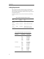
1
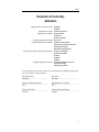
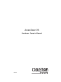
Access Server 316
Hardware Owner’s Manual
9032858
Notice
Notice
Cabletron Systems reserves the right to make changes in specifications and other information
contained in this document without prior notice. The reader should in all cases consult Cabletron
Systems to determine whether any such changes have been made.
The hardware, firmware, or software described in this manual is subject to change without notice.
IN NO EVENT SHALL CABLETRON SYSTEMS BE LIABLE FOR ANY INCIDENTAL, INDIRECT,
SPECIAL, OR CONSEQUENTIAL DAMAGES WHATSOEVER (INCLUDING BUT NOT LIMITED
TO LOST PROFITS) ARISING OUT OF OR RELATED TO THIS MANUAL OR THE INFORMATION
CONTAINED IN IT, EVEN IF CABLETRON SYSTEMS HAS BEEN ADVISED OF, KNOWN, OR
SHOULD HAVE KNOWN, THE POSSIBILITY OF SUCH DAMAGES.
© July 1999 by:
Cabletron Systems, Inc.
35 Industrial Way
Rochester, NH 03867
All Rights Reserved
Printed in the United States of America
Order Number: 9032858
Cabletron Systems is a registered trademark of Cabletron Systems, Inc.
DEC, DEChub, DIGITAL, and the DIGITAL logo are trademarks of Compaq Computers, Inc.
Ethernet is a trademark of Xerox Corporation.
All other trademarks or registered trademarks are the property of their respective holders.
i
Notice
FCC Notice
This device complies with Part 15 of the FCC rules. Operation is subject to the following two
conditions: (1) this device may not cause harmful interference, and (2) this device must accept any
interference received, including interference that may cause undesired operation.
NOTE: This equipment has been tested and found to comply with the limits for a Class A digital
device, pursuant to Part 15 of the FCC rules. These limits are designed to provide reasonable
protection against harmful interference when the equipment is operated in a commercial environment.
This equipment uses, generates, and can radiate radio frequency energy and if not installed in
accordance with the operator’s manual, may cause harmful interference to radio communications.
Operation of this equipment in a residential area is likely to cause interference in which case the user
will be required to correct the interference at his own expense.
WARNING: Changes or modifications made to this device which are not expressly approved by the
party responsible for compliance could void the user’s authority to operate the equipment.
VCCI Notice
This is a Class A product based on the standard of the Voluntary Control Council for Interference by
Information Technology Equipment (VCCI). If this equipment is used in a domestic environment,
radio disturbance may arise. When such trouble occurs, the user may be required to take corrective
actions.
Industry Canada Notice
This digital apparatus does not exceed the Class A limits for radio noise emissions from digital
apparatus set out in the Radio Interference Regulations of the Canadian Department of
Communications.
Le présent appareil numérique n'émet pas de bruits radioélectriques dépassant les limites applicables
aux appareils numériques de la class A prescrites dans le Règlement sur le brouillage radioélectrique
édicté par le ministère des Communications du Canada.
ii
Notice
Declaration of Conformity
Addendum
Application of Council Directive(s): 89/336/EEC
73/23/EEC
Manufacturer’s Name: Cabletron Systems, Inc.
Manufacturer’s Address: 35 Industrial Way
European Representative Name:
European Representative Address:
Conformance to Directive(s)/Product Standards:
Equipment Type/Environment:
PO Box 5005
Rochester, NH 03867
Mr. J. Solari
Cabletron Systems Limited
Nexus House, Newbury Business Park
London Road, Newbury
Berkshire RG13 2PZ, England
EC Directive 89/336/EEC
EC Directive 73/23/EEC
EN 55022
EN 50082-1
EN 60950
Networking Equipment, for use in a
Commercial or Light
Industrial Environment.
We the undersigned, hereby declare, under our sole responsibility, that the equipment packaged with
this notice conforms to the above directives.
Mr.
Ronald Fotino
____________________________________________________
Full Name
Mr. J. Solari
______________________________________________________
Principal Compliance Engineer
____________________________________________________
Managing Director - E.M.E.A.
______________________________________________________
Title
Title
Rochester,
NH, USA
____________________________________________________
Location
Newbury, Berkshire, England
______________________________________________________
Full Name
Location
iii
Notice
iv
Contents
Preface
Using This Guide ........................................................................................................... vii
Intended Audience......................................................................................................... vii
Structure of This Guide ................................................................................................. vii
Document Conventions ...............................................................................................viii
Related Documentation................................................................................................viii
Getting Help .................................................................................................................... ix
Chapter 1
Hardware Overview
Model 316 ....................................................................................................................... 1-2
Controls, Indicators, and Connectors......................................................................... 1-2
Understanding the Software Loading........................................................................ 1-5
Loading from Flash RAM ..................................................................................... 1-5
Loading from the Network................................................................................... 1-5
Chapter 2
Checking the Site
Physical Requirements ................................................................................................. 2-2
Environmental Requirements ..................................................................................... 2-3
Electrical Requirements................................................................................................ 2-4
Chapter 3
Cabling the Site
Preinstallation Checks .................................................................................................. 3-1
Installing the Ethernet Cables and Devices............................................................... 3-2
Installing Serial Cables and Devices on the Access Server 316 .............................. 3-2
Cabling Requirements .................................................................................................. 3-4
Standard Ethernet Connection............................................................................. 3-5
10BaseT Ethernet Connection .............................................................................. 3-5
ThinWire Ethernet Connection ............................................................................ 3-5
Installing the Access Server 316 in a Rack ................................................................. 3-6
Installing the Access Server 316 on a Desktop.......................................................... 3-9
v
Contents
Chapter 4
Connector and Cable Pin Descriptions
Connector Pin Descriptions ......................................................................................... 4-1
Standard Ethernet .................................................................................................. 4-2
10BaseT Ethernet.................................................................................................... 4-3
Access Server 316 Serial Line Ports ..................................................................... 4-4
Cable Connections......................................................................................................... 4-5
Cabling and Adapters Used with Access Server 316 ............................................... 4-6
Chapter 5
Replacing and Adding Memory
Swapping or Replacing an Access Server 316 Unit .................................................. 5-1
Replacing a Faulty Single-In-Line Memory Module................................................ 5-2
Additional Memory Supported ................................................................................ 5-10
Installing Extra Memory ............................................................................................ 5-11
Chapter 6
Replacing and Adding Flash RAM
Replacing or Adding Flash RAM................................................................................ 6-2
Chapter 7
What to Do If You Have Problems
Diagnosing Problems.................................................................................................... 7-2
Seven-Segment Display Off and System OK LED Off............................................. 7-3
System OK LED Off / Seven-Segment Display Flashing “C”, “d”, or “n” .......... 7-3
System OK LED Off / Seven-Segment Display Flashing........................................ 7-4
System OK LED Flashing............................................................................................. 7-4
Error Messages ....................................................................................................... 7-4
Seven-Segment Display Shows a “3” ......................................................................... 7-6
Downline Load Starts, Then Fails........................................................................ 7-6
Downline Load Does Not Start ............................................................................ 7-7
Seven-Segment Display Codes.................................................................................... 7-7
Network Activity LED.................................................................................................. 7-8
vi
Preface
This manual describes how to use the Access Server 316. It also provides problem
solving, connector and adapter, and pin assignment information.
Using This Guide
Read through this guide completely to understand the interface module features,
capabilities, and Local Management functions. A general working knowledge of
Ethernet and IEEE 802.3-type data communications networks and their physical
layer components is helpful when using these devices.
Intended Audience
This manual is intended for use by the hardware installer. The installer is
responsible for ensuring that the hardware is installed and tested. This manual
shows how to install when the site is verified and the cables and devices are in
place. It also shows how to verify the site, install cables and devices, and
troubleshoot problems. The person installing the software can then verify the
system installation.
Structure of This Guide
This guide is organized as follows:
Chapter
Title
Description
1
Hardware Overview
Outlines the contents of this manual, describes the
features of the Access Server 316, provides instructions
on obtaining additional help and concludes with a list
of related manuals.
2
Checking the Site
Lists the physical, environmental, and electrical
requirements.
3
Cabling the Site
Provides instructions on how to cable your site.
4
Connector and Cable Pin
Descriptions
Shows the connector and pin assignments.
vii
Preface
Chapter
Title
Description
5
Replacing and Adding
Memory
Shows how to install extra memory and replace faulty
memory.
6
Replacing and Adding
Flash RAM
Shows how to update with flash RAM.
7
What to Do If You Have
Problems
Describes what to do if you encounter a problem.
Document Conventions
Throughout this guide, the following symbols are used to call attention to
important information.
Note symbol. Calls the reader’s attention to any item of information that may be
NOTE
!
of special importance.
Caution symbol. Contains information essential to avoid damage to the
equipment.
CAUTION
Related Documentation
The following documents may help the user to set up and manage the Network
Access Server 316:
viii
Title
Part Number
Network Access Server 316 Hardware Owner’s Manual
9032858
Network Access Software Management Guide
9032859
Network Access Software Commands Reference Manual
9032860
Network Access Software Problem Solving Guide
9032861
Network Access Software Installation Guide
9032862
Preface
Title
Part Number
Cabletron RADIUS Server Installation Guide
9032863
Cabletron RADIUS Server Management Guide
9032864
The manuals referenced above can be viewed or printed from the CD-ROM
included with the Access Server 316 or can be obtained on the World Wide Web in
Adobe Acrobat Portable Document Format (PDF).
Getting Help
For additional support related to this device or document, contact Cabletron
Systems using one of the following methods:
World Wide Web
http://www.cabletron.com/
Phone
(603) 332-9400
Internet mail
[email protected]
FTP
ftp://ftp.cabletron.com/
anonymous
your email address
Login
Password
To send comments or suggestions concerning this document, contact the Cabletron
Systems Technical Writing Department via the following
email address: [email protected]
Make sure to include the document Part Number in the email message.
Before calling Cabletron Systems, have the following information ready:
•
Your Cabletron Systems service contract number
•
A description of the failure
•
A description of any action(s) already taken to resolve the problem (e.g.,
changing mode switches, rebooting the unit, etc.)
•
The serial and revision numbers of all involved Cabletron Systems products in
the network
•
A description of your network environment (layout, cable type, etc.)
•
Network load and frame size at the time of trouble (if known)
•
The device history (i.e., have you returned the device before, is this a recurring
problem, etc.)
•
Any previous Return Material Authorization (RMA) numbers
ix
Preface
x
Chapter 1
Hardware Overview
The Access Server 316 connects devices (such as printers, terminals, PCs, and
modems) to local area networks (LANs). The Access Server 316 is Ethernet/IEEE
802.3-based and supports standard Ethernet/IEEE 802.3 and l0BaseT Ethernet/
IEEE 802.3 directly, and ThinWire Ethernet/IEEE 802.3 through an adapter. The
Access Server 316 can be installed on a desktop or in a 19-inch rack. The Access
Server 316 supports Flash RAM capability and other nonvolatile forms of
memory. The Access Server 316 is shipped with Flash RAM installed. Should the
Flash RAM ever fail, it can be ordered separately and replaced on the Access
Server 316.
The Access Server 316 can download the software image from the network or
from the Flash RAM option. The Flash RAM option allows for a boot/powerup
without having to download the image through the network. The Access Server
316 will support up to 8 Mbytes of memory with the use of two single-in-line
modules (SIMs). These SIMs can be installed as memory updates by the customer.
This chapter includes the following topics:
•
Model 316
•
Controls, Indicators and Connectors
•
Understanding the Software Loading
1-1
Hardware Overview
Model 316
The Access Server 316 supports TIA/EIA-423-B signal levels on 16 MJ8
connectors. Use the Access Server 316 to connect devices such as terminals,
printers, modems, bar-code readers, or personal computers in terminal
emulation mode. You can connect the Access Server 316 directly or, where
required, using special adapters (see Chapter 3).
NOTES
Adapter H8585-AB and H8585-AC are not for connection to public networks in
Sweden, Germany, or Japan.
Figure 1-1. Access Server 316 Rear View
Controls, Indicators, and Connectors
All of the Access Server 316 controls, indicators, and connectors are located on the
rear, as shown in Figure 1-1, with the exception of the System OK LED, which is
duplicated on the front of the Access Server 316 (Figure 1-2).
1-2
Hardware Overview
Figure 1-2. Access Server 316 Front View
Table 1-1 describes the Access Server 316 controls.
Table 1-1. Access Server 316 Controls
Control
Description
System reset switch
On power up, press this switch until E appears on the
Seven-segment display. This reloads the factory set
parameters. During Flash load (three horizontal segments of
the Seven-segment LED), pressing and holding the system
reset switch will abort the Flash RAM load and force a
network boot. See Chapter 7 for more information.
Ethernet select switch
This switch selects either standard or 10BaseT Ethernet.
Table 1-2 describes the indicators.
Table 1-2. Access Server 316 Indicators
Indicator
Display
System OK LED
Lights (green) when the Access Server 316 has passed
self-test. Blinks when a nonfatal error occurs on self-test.
When off, indicates that the Access Server 316 has failed
self-test.
Network Activity
LED
Refer to Table 1-3.
Seven-Segment
Display
Provides error and status information.
1-3
Hardware Overview
Table 1-3 describes the LEDs.
Table 1-3. Network Activity LED
Ethernet
Selected
Connection Status
LED Display
10BaseT
Open/incorrectly terminated
OFF
Correctly terminated/no network activity
ON
Correctly terminated/network activity
Flashing (rate independent of
network activity).
Open on network activity
OFF
Correctly connected/no network activity
OFF
Correctly connected/network activity
Flashing or ON, depending
on network activity.
Standard
Table 1-4 describes the connectors. For additional information on the connectors,
refer to Chapter 4.
Table 1-4. Access Server 316 Connectors
1-4
Connector
Description
Serial port connectors
These 16 female MJ8 connectors connect asynchronous serial
devices to the Access Server 316.
Standard Ethernet
connector
This single 15-pin female D-connector connects to a standard
Ethernet/IEEE 802.3 local area network using a transceiver
cable.
10BaseT Ethernet
connector
This single female MJ8 connector connects to a 10BaseT
Ethernet/IEEE 802.3 local area network.
Power cord receptacle
The Access Server 316 power cord plugs into this receptacle.
Hardware Overview
Understanding the Software Loading
This section describes the two methods for loading software.
Loading from Flash RAM
Once the Access Server 316 completes self-tests, it checks for Flash RAM. If there
is a valid Flash RAM, the Access Server 316 begins the boot sequence to load the
software from Flash RAM. The Seven-segment display will display three
horizontal segments during this Flash RAM loading phase.
If the Access Server 316 does not have Flash RAM, or if the name of the image in
Flash RAM does not match the image name the Access Server 316 is attempting to
load, it proceeds to a network load.
If a device is connected to the console port, the Access Server 316 can display
status messages while the boot sequence is running. Status messages indicate the
Ethernet address of the Access Server 316, the name of the load image it is looking
for, and the current stage of the boot process.
Loading from the Network
If you do not want to load the software from Flash RAM, you can press the
system reset switch during load from Flash RAM (three horizontal segments
displayed on the Seven-segment display). When the system reset switch is
pressed, the Flash RAM load will be aborted and the software is downline loaded
from a load host.
When the Access Server 316 notices that the system reset switch depressed during
a load from Flash RAM, it will rapidly blink the LED to acknowledge the pressed
system reset switch (this may take several seconds). Once the LED begins rapidly
blinking, you may release the system reset switch and the firmware will go on to a
network boot sequence. For more information on display codes for Flash RAM
(See section titled Seven-Segment Display Codes on page 7-7).
1-5
Hardware Overview
1-6
Chapter 2
Checking the Site
The Access Server 316 can operate in an office environment and in a standard
equipment rack located in a computer room or satellite equipment room.
Regardless of where you install the Access Server 316, verify that all of the
requirements in this section are met before beginning the installation.
This chapter includes the following sections:
•
•
•
Physical Requirements
Environmental Requirements
Electrical Requirements
2-1
Checking the Site
Physical Requirements
Allow for 15 cm (6 in) of airspace around the Access Server 316 air vents.
Table 2-1 shows the size and weight of the Access Server 316.
Table 2-1. Physical Specifications of the Access Server 316
Dimension
Measurement
Height
44 mm (1.73 in)
Width
442 mm (17.4 in)
Depth
282 mm (11.1 in)
Weight
2.5 kg (5.51 lbs)
Table 2-2 shows the acoustic parameters.
Table 2-2. Acoustical Parameters
Parameter
Measurement
LWAd1
4.1 bels (LWA = 3.8 bels)
Lpam (bystander)
27 dBA
1. Preliminary declared values per ISO 9296 and
ISO 7779. Current values are available from
respresentatives.
2-2
Checking the Site
Environmental Requirements
Environmental requirements for temperature and humidity must be within the
ranges shown in Table 2-3.
Table 2-3. Environmental Specifications of the Access Server 316
Parameter
Minimum
Maximum
Operating
5o C (41o F)
50o C (122o F)
Nonoperating
- 40o C (- 40o F)
66o C (151o F)
Temperature1
20o C (36o F)
Maximum rate of
temperature change per hour
Altitude
Operating
2438 m (8000 ft)
Nonoperating
4876 m (16000 ft)
Relative Humidity
Operating (noncondensing)
10%
95%
Nonoperating (noncondensing)
10%
95%
1. For high altitude sites, decrease the operating temperature
specification by 1.8o C for each 1000 m (1o F for each 1000 ft) above sea
level.
2-3
Checking the Site
Electrical Requirements
The power at the electrical outlet must match the requirements shown in
Table 2-4.
The instructions assume that an appropriate AC power source is within 1.8 m
(6.0 ft) of Access Server 316.
Table 2-4. Electrical Requirements
Parameter
Access Server 316
Line voltage1
100–120 V rms/220–240 V rms
Frequency
50/60 Hz
Line current
1.0 A rms/.5 A rms
Power
68W
1. The Access Server 316 automatically selects the
voltage range.
Table 2-5 shows the electrical output from the standard Ethernet/IEEE 802.3
connector.
Table 2-5. Standard Ethernet/IEEE 802.3 Connector Output
2-4
Parameter
Access Server 316
Voltage
+ 12 V DC
Current
0.5 A Max
Chapter 3
Cabling the Site
This chapter shows you how to install the cables and associated devices used by
the Access Server 316.
This chapter includes the following sections:
•
•
•
•
•
•
Preinstallation Checks
Installing the Ethernet Cables and Devices
Installing Serial Cables and Devices on the Access Server 316
Cabling Requirements
Installing the Access Server 316 in a Rack
Installing the Access Server 316 on a Desktop
Preinstallation Checks
Before beginning the Access Server 316 installation, use the following checklist to
make sure that the site preparation is complete:
•
Arrangements have been made to connect the Access Server 316 Ethernet port
to an Ethernet interface device (if required).
•
The Ethernet interface device is installed and the required cabling is in place,
tested, and tagged.
•
The rack-mount kit is installed (if required), as described in later in this chapter.
•
Cables of appropriate length are available for connecting the Access Server 316
to the Ethernet interface device.
•
The devices (terminals, modems, personal computers, hosts) are ready to be
connected.
3-1
Cabling the Site
•
Cables of appropriate length and type are available for connection of serial
devices.
•
One terminal (asynchronous TIA/EIA-423 or EIA/TIA-232-D compatible) is
available for hardware testing and system verification.
Installing the Ethernet Cables and Devices
You can connect the Access Server 316 to:
•
Standard Ethernet/IEEE 802.3 network
•
lOBaseT Ethernet/IEEE 802.3 network
•
ThinWire Ethernet/IEEE 802.3 network using an external media access unit
(MAU)
Installing Serial Cables and Devices on the Access
Server 316
The Access Server 316 can be configured by the software to support one of the two
sets of signals. One set consists of:
•
•
•
•
Clear to send (CTS)—This is the default setting.
Request to send (RTS)—This is the default setting.
Data set ready (DSR)—This is the default setting.
Data terminal ready (DTR)—This is the default setting.
The second set consists of:
•
•
•
•
Ring indicator (RI)
Data signal rate selector (DSRS)
Data carrier detect (DCD)
Data terminal ready (DTR)
Before installing cables to the Access Server 316, you must find out which modem
signals are supported from the person managing the Access Server 316. This
information is necessary to determine which cables to use. For more information
on the signals, refer to the Network Access Software Management guide.
Use the cables listed and described in the following table to connect to the 8-pin
modular jacks on the serial communication lines of the Access Server 316.
3-2
Cabling the Site
Table 3-1. Cables and Adapters for the Access Server 316
NOTE
Cable and Adapters
Description
BN25G MP8 to
MP8 Equipment Cable
Use this 8-wire pin-to-pin cable to connect to
H8585-xx series adapters.
BN24H MP8 to
MMP6 (modified
modular plug) Office Cable
Use this cable to connect to the 6-pin modified
modular jack (MMJ) of H8575-xx series
adapters or to a DEC-style printer or terminal.
H8575-A (EIA 423-B to
EIA-232-D) Adapter
Use this adapter and the BN24H cable to
connect to 25-pin D-sub male connectors (for
example: printers).
H8575-B Adapter
Use this adapter and the BN24H cable to
connect to 9-pin D-sub male connectors.
H8575-D (E1A423-B to
EIA-232-D) Adapter
Use this adapter and the BN24H cable to
connect to 25-pin D-sub female connectors.
H8585-AA MJ8 to
DB9 (female) Null-Modem
Adapter
Use this adapter with the BN25G cable to
convert the Access Server 316 connector to DB9
(female) connector for cabling to PC
asynchronous ports.
H8585-AB MJ8 to
DB25 (male) Modem Adapter
Can be used with the BN25G cable to connect
low speed modems to the Access Server 316.
Refer to Chapter 4 for further information.
H8585-AC MJ8 to
DB25 (male) Modem Adapter
Can be used with the BN25G cable to connect
high speed modems to Access Server 316. Refer
to Chapter 4 for further information.
Adapters H8585-AB and H8585-AC are not for connection to public networks in
Sweden, Germany, or Japan.
3-3
Cabling the Site
Cabling Requirements
Table 3-2 shows the maximum communication distances for different types of
cable used between the Access Server 316 and the Ethernet device. Table 3-3
shows the maximum cable lengths for a number of data rates using Access Server
316 supported line protocols.
The cabling requirements of the Access Server 316 are shown in the following
sections.
Table 3-2. Maximum Communications Distances—Ethernet
From
To
Maximum
Distance
Cable
Type
Access
Server 316
Transceiver
50 m (164 ft)
BNE3x-xx standard transceiver cable
Access
Server 316
Transceiver
12.5 m (41 ft)
BNE4x-xx office transceiver cable
Access
Server 316
Repeater
100 m (328 ft)
BN24Q cable (cross-over type)
BN25G (straight-through type)
Table 3-3. Maximum Cable Lengths—Access Server 316 to Devices
3-4
Line Protocol
Data Rate (b/s)
Cable Length
EIA/TIA-432-A/V.10
4.8 K
9.6 K
19.2 K
38.4 K
57.6 K
115.2 K
500 m (1500 ft)
280 m (900 ft)
150 m (500 ft)
85 m (280 ft)
30 m (100 ft)
12 m (40 ft)
EIA/TIA 423
9.6 K
19.2 K
38.4 K
57.6 K
115.2 K
900 m (3000 ft)
300 m (1000 ft)
150 m (500 ft)
60 m (200 ft)
30 m (100 ft)
EIA/TIA-232-E/V.28
9.6 K
19.2 K
38.4 K
57.6 K
115.2 K
60 m (200 ft)
30 m (100 ft)
15 m (50 ft)
6 m (20 ft)
3 m (10 ft)
Cabling the Site
!
CAUTION
Do not use structured building wiring or bundled type breakout cables at baud
rates above 38.4 K. Separate point to point cables are recommended at baud rates
above 38.4 K.
Standard Ethernet Connection
The transceiver cable must not exceed the maximum distances listed in Table 3-2.
10BaseT Ethernet Connection
The 10BaseT Ethernet installation must conform to the following configuration
rules:
•
The twisted-pair cable must not exceed the maximum distance listed in
Table 3-2.
•
No other signal should be used in the same cable sheath. For example, voice
and data signals cannot be run within the same sheath.
•
Unshielded twisted-pair cable must remain at least 30.48 cm (12 in) from any
type of high-voltage power device or electrical noise source.
ThinWire Ethernet Connection
The ThinWire cable segment must conform to the following configuration rules:
•
The maximum cable segment length must not exceed 185 m (606 ft).
•
There must be a 50-ohm terminator at each end of the cable segment.
•
There must be only one ground per cable segment.
•
There must be at least 0.5 m (19 in) between T-connectors.
•
The maximum number of stations, between terminators, must not exceed 30
stations.
•
ThinWire cable segments must not be configured in a loop.
•
ThinWire cable segments must not have any branch segments.
3-5
Cabling the Site
Installing the Access Server 316 in a Rack
You can rack mount the Access Server 316 in any one of four ways (Table 3-4)
depending on how you install the brackets.
Table 3-4. Installing the Access Server 316 Brackets
3-6
Access Server 316 Installation
Bracket Installation
1.
Flush with rear facing outward
Flush with rear
2.
Recessed 2.54 cm (1 in)
with rear facing outward
Forward 2.54 cm (1 in) from rear
3.
Flush with front facing outward
Flush with front
4.
Recessed 2.54 cm (1 in)
with front facing outward
Forward 2.54 cm (1 in) from rear
Cabling the Site
Figure 3-1 shows how to install the brackets in order to recess the Access
Server 316.
Figure 3-1. Access Server 316 Bracket Installation
3-7
Cabling the Site
Figure 3-2 shows how to remove the brackets from the Access Server 316.
Figure 3-2. Access Server 316 Bracket Removal
3-8
Cabling the Site
Installing the Access Server 316 on a Desktop
To install the Access Server 316 on a desktop:
Step
Action
1
Turn the Access Server 316 upside down.
2
Remove the backing from the feet.
3
Stick the feet to the Access Server 316.
3-9
Cabling the Site
3-10
Chapter 4
Connector and Cable Pin
Descriptions
This chapter describes the pins of the Access Server 316 hardware connectors and
the cables used to interface to the Access Server 316 hardware. Wiring diagrams of
the individual cables are included to help you in troubleshooting and cable
building.
This chapter includes the following sections:
•
•
•
Connector Pin Descriptions
Cable Connections
Cabling and Adapters Used with Access Server 316
Connector Pin Descriptions
This section describes the pins for the following Access Server 316 connectors:
•
•
•
Standard Ethernet/IEEE 802.3 transceiver interface
10BaseT Ethernet/IEEE 802.3 transceiver interface
Access Server 316 serial port connectors
4-1
Connector and Cable Pin Descriptions
Standard Ethernet
Figure 4-1 shows how the pins are numbered on a standard Ethernet transceiver
interface connector and Table 4-1 lists the signals for the standard Ethernet
connector pins.
Figure 4-1. Pin Numbers and Signals for Standard Ethernet Connector
Table 4-1. Signal Names for Standard Ethernet Connector Pins
4-2
Pin No.
Signal Name
1
Shield
2
Collision Presence +
3
Transmit +
4
Reserved
5
Receive +
6
+ 12 Volt Power Return
7
Reserved
8
Reserved
9
Collision Presence -
10
Transmit -
11
Reserved
12
Receive -
13
+12 Volt Power
14
Reserved
15
Reserved
Connector and Cable Pin Descriptions
10BaseT Ethernet
The 10BaseT Ethernet connector is an 8-pin modular jack (MJ8). Figure 4-2 shows
how the pins are numbered on a 10BaseT Ethernet connector and Table 4-2 lists
the signals for the 10BaseT Ethernet connector.
Figure 4-2. Pin Numbers and Signals for 10BaseT Ethernet Connector
Table 4-2. Signal Names for 10BaseT Ethernet Connector Pins
Pin No.
Signal Name
1
Transmit +
2
Transmit -
3
Receive +
4
Reserved
5
Reserved
6
Receive -
7
Reserved
8
Reserved
4-3
Connector and Cable Pin Descriptions
Access Server 316 Serial Line Ports
The Access Server 316 uses an MJ8 connector on the serial ports. Figure 4-3 shows
how the pins are numbered on the MJ8 connector and Table 4-3 lists the signals on
the pins. You can set pins 4, 5, and 8 to either CTS, RTS, DSR or RI, DSRS, DCD.
Figure 4-3. Pin Numbers and Signals for the MJ8 Connector
Table 4-3. Signal Names and Default Values for MJ8 Connector Pins
Software
Default1
Software
Alternative1
CTS or RI (selected by software)
CTS
RI
5
RTS or DSRS (selected by software)
RTS
DSRS
6
TXD
7
DTR
8
DSR or DCD (selected by software)
DSR
DCD
Pin No.
Signal Name
1
RXD GND
2
RXD
3
TXD GND
4
1. To change default values, refer to the Cabletron Network Access Software
Management Guide.
4-4
Connector and Cable Pin Descriptions
Cable Connections
Table 4-4 describes the cable connections that are compatible with the Access
Server 316 Ethernet and serial line connectors. Wiring diagrams of individual
cables are provided for use in troubleshooting and cable building.
Table 4-4. Cable Connections
NOTE
Cable Type
Description
10BaseT Ethernet Cable
The 10BaseT Ethernet cable uses an 8-pin modular
plug on each end.
BN25G MP8 to
MP8 Equipment Cable
The BN25G is a four twisted-pair cable with
standard 8-pin modular plugs.
H8585-AA MJ8 to
DB9 Null-Modem Adapter
The H8585-AA MJ8 to DB9 null-modem adapter is
used to convert the serial port to a DB9 female
connector for asynchronous connection to a PC port.
BN24H MP8 to
MP6 Office Cable
The BN24H is a three twisted-pair cable with a
standard 8-pin modular plug on one end and a 6-pin
modular plug on the other.
H8585-AB MJ8 to
DB25 Modem Adapter
The H8585-AB MJ8 to DB25 low speed modem
adapter is used to convert a serial port to the DB25
configuration. Used for older styles of modems.
H8585-AC MJ8 to
DB25 Modem Adapter
The H8585-AC MJ8 to DB25 high speed modem
adapter is used to convert a serial port to the DB25
configuration.
Adapters H8585-AB and H8585-AC are not for connection to public networks in
Sweden, Germany, or Japan.
4-5
Connector and Cable Pin Descriptions
Cabling and Adapters Used with Access Server 316
The following figures illustrate the cabling and adapters used that can be used
with the Access Server 316.
Figure 4-4. Crossover Cable Connection
4-6
Connector and Cable Pin Descriptions
Figure 4-5. Crossover and Straight-Through Cable Connections
4-7
Connector and Cable Pin Descriptions
4-8
Chapter 5
Replacing and Adding Memory
This chapter describes and illustrates the procedures for handling single-in-line
memory modules (SIMs) and Flash RAM when swapping out an Access Server
316 unit, and it shows how to replace a faulty SIM and add memory.
This chapter includes the following sections:
•
•
•
•
Swapping or Replacing an Access Server 316 Unit
Replacing a Faulty Single-In-Line Memory Module
Additional Memory Supported
Installing Extra Memory
Swapping or Replacing an Access Server 316 Unit
Whenever an Access Server 316 unit is replaced, the Single In-Line Memory
Modules (SIMs) and FLASH CARD must be REMOVED from the old unit and reinstalled in the replacement. The removable Flash Card is used for installation of
the Network Access Software and is not required for the operation of the unit.
Before an Access Server 316 is swapped, assure that at least one memory SIM is
installed. Please refer to the following chapters for the correct procedure for
removing and installing SIMs and Flash Cards.
!
CAUTION
SIMs are sensitive to static and are packed in anti-static packaging. Electrostatic
Discharge (ESD) can cause failure of electronic components and can reduce the
long term reliability of the Access Server 316. Cabletron recommends that you use
an anti-static kit or ESD wrist strap when handling SIMs.
5-1
Replacing and Adding Memory
Replacing a Faulty Single-In-Line Memory Module
To replace a SIM:
1. Disconnect all cables from the Access Server 316.
2. Remove the Access Server 316 brackets (if fitted) (Figure 5-1).
Figure 5-1. Replace Unit
5-2
Replacing and Adding Memory
3. Remove the Access Server 316 cover (Figure 5-2).
Figure 5-2. Cover Removal
5-3
Replacing and Adding Memory
4. Fit the anti-static kit (Figure 5-3).
Figure 5-3. Anti-Static Wrist Guard
5-4
Replacing and Adding Memory
5. Locate the SIM connectors (Figure 5-4).
Figure 5-4. SIM Location
5-5
Replacing and Adding Memory
6. Remove the faulty SIM (Figure 5-5).
Figure 5-5. SIM Removal
5-6
Replacing and Adding Memory
7. Insert the replacement SIM into the connector (Figures 5-6 & 5-7).
Figure 5-6. SIM Replacement
5-7
Replacing and Adding Memory
Figure 5-7. Adding an Additional SIM
5-8
Replacing and Adding Memory
8. Remove the anti-static kit.
9. Replace the cover (Figure 5-8).
Figure 5-8. Cover Replacement
10. Connect a terminal to the Access Server 316 (See section titled System OK LED
Flashing on page 7-4.).
11. Reconnect the cables and test the Access Server 316.
When you plug in the power cable, the Access Server 316 runs self-tests. After
the tests are completed, the Access Server 316 requests a load from Flash
RAM. If Flash RAM is installed, three horizontal segments will be displayed.
To abort Flash RAM load and to load from the network, press and hold the
system reset switch until the display flashes. The Seven-segment display will
alternate between 3 and 4 until the software is loaded from the network.
Allow 3 minutes for the Access Server 316 to complete the procedure.
5-9
Replacing and Adding Memory
Alternatively, connect a terminal to the console port of the Access Server 316,
using 9600 baud, 8 bits, and no parity. Wait for the status messages to appear
on the terminal indicating a Flash RAM load is in progress. Enter Ctrl-B twice
on the keyboard. In response to the “>>>” prompt, enter the following
command:
>>>b eth:wweng2
If you are using a special load image file, use that file name in place of
wweng2.
NOTE
If the SIM memory is faulty, the Access Server 316 flashed "C" if the faulty SIM
is in connector 1 and "d" if the faulty SIM is in connector 2. If you install the
wrong type SIM, the Access Server 316 flashes "n". Remove or replace the SIM to
repair the Access Server 316.
12. Check status message 960 to verify memory size:
Local -960- Available memory 4 Mbytes
Additional Memory Supported
You can increase the memory of your Access Server 316 by adding extra single-inline memory modules (SIMs). The Access Server 316 contains 4 Mbytes of SIM
memory. However, future releases of Access Server 316 software may contain
additional functions that require more SIM memory. You can install the additional
SIM memory on site. Adding an additional 4-Mbyte SIM will increase the
memory to the maximum of 8 Mbytes.
The Access Server 316 supports 4-Mbyte SIMs (1M x 36).
There are two SIM connectors on the Access Server 316 printed circuit board. One
of the connectors contains the factory installed 4-Mbyte SIM (Figure 5-4).
The Access Server 316 supports only SIMs with the following access times:
•
•
80 nano seconds
70 nano seconds
The Access Server 316 supports only SIMs in the following configurations:
•
•
5-10
4 Mbytes (one 4-Mbyte SIM in any connector)
8 Mbytes (one 4-Mbyte SIM per connector)
Replacing and Adding Memory
NOTE
The Access Server 316 supports only 36-bit-wide SIMs. If you are not using
Cabletron Systems SIMs, check the specification of your SIM to verify that it is
36-bit-wide. SIMs that are not 36-bit-wide will not work but may not be detected
by the Access Server 316 diagnostics.
Installing Extra Memory
To install a SIM:
NOTE
Step
Action
1
Disconnect all cables from the Access Server 316.
2
Remove the Access Server 316 brackets, if fitted (Figure 5-1).
3
Remove the Access Server 316 cover (Figure 5-2).
4
Fit the anti-static kit (Figure 5-3).
5
Locate the SIM connectors (Figure 5-4).
6
Remove the SIM from its wrappings and keep the memory label.
7
Insert the extra SIM in the connector (Figure 5-7).
8
Remove the anti-static kit.
9
Replace the cover (Figure 5-8).
10
Connect a terminal to the Access Server 316 (see the section titled System OK
LED Flashing, in Chapter 7).
11
Reconnect the cables and test the Access Server 316.
12
When you plug in the power cable, the Access Server 316 runs a self-test. After
the tests are completed, the Access Server 316 requests a load from Flash RAM.
If Flash RAM is installed, three horizontal segments will be displayed. To
abort Flash RAM load and to load from the network, press and hold the
system reset switch until the display flashes. The Seven-segment display will
alternate between 3 and 4 until the software is loaded from the network. Allow
3 minutes for the Access Server 316 to complete the procedure.
13
Compare the Seven-segment display and the System OK LED status with the
information in Table 7-1.
14
Check status message 960 to verify memory size:
Local -960- Available memory 4 Mbytes
If the SIM memory is faulty, the Access Server 316 flashes “C” if the faulty SIM
is in connector 1 and “d” if the faulty SIM is in connector 2. If you install the
wrong type SIM, the Access Server 316 flashes “n”. Remove or replace the SIM to
repair the Access Server 316.
5-11
Replacing and Adding Memory
5-12
Chapter 6
Replacing and Adding Flash RAM
This chapter shows how to replace or update an Access Server 316 Flash RAM
Card.
NOTE
Electrostatic Discharge (ESD) can cause failure of electronic components and can
reduce the long term reliability of the Access Server 316. Cabletron Systems
recommends you use an anti-static kit or ESD wrist strap when installing a Flash
RAM Card.
This chapter includes the following section:
•
Replacing or Adding Flash RAM
6-1
Replacing and Adding Flash RAM
Replacing or Adding Flash RAM
To replace or install the Flash RAM Card:
1. Disconnect all cables from the Access Server 316.
2. Remove the Access Server 316 brackets, if fitted (Figure 6-1).
Figure 6-1. Removing the Brackets
6-2
Replacing and Adding Flash RAM
3. Remove the Access Server 316 cover (Figure 6-2).
Figure 6-2. Removing the Cover
6-3
Replacing and Adding Flash RAM
4. Fit the anti-static kit (Figure 6-3).
Figure 6-3. Fitting the Anti-Static Kit
6-4
Replacing and Adding Flash RAM
5. Locate the Flash RAM connector or remove the faulty Flash RAM Card
(Figure 6-4).
Figure 6-4. Locating the Flash RAM Connector/Removing Faulty Flash RAM Card
6-5
Replacing and Adding Flash RAM
6. Insert the replacement or Flash RAM Card update in the connector (Figure
6-5).
Figure 6-5. Inserting the Replacement or Flash RAM Card Update
NOTE
6-6
The Flash RAM socket is keyed. Ensure that you follow the instructions located
on the Flash RAM card when installing.
Replacing and Adding Flash RAM
7. Remove the anti-static kit.
8. Replace the cover (Figure 6-6).
Figure 6-6. Replacing the Cover
9. Connect a terminal to the Access Server 316 (See section titled System OK LED
Flashing on page 7-4).
6-7
Replacing and Adding Flash RAM
10. Reconnect the cables and test the Access Server 316.
When you plug in the power cable, the Access Server 316 runs a self-test. After
the tests are completed, the Access Server 316 requests a load from Flash
RAM. If Flash RAM is installed, three horizontal segments will be displayed.
To abort Flash RAM load and to load from the network, press and hold the
system reset switch until the display flashes. The Seven-segment display will
alternate between 3 and 4 until the software is loaded from the network.
Allow 3 minutes for the Access Server 316 to complete the procedure.
11. Compare the Seven-segment display and the System OK LED status with
Table 6-1.
Table 6-1. LED Status
Device
Definition
State
Indication
Corrective
Action
System OK
LED
Diagnostic
On
Self-test passed
-
Off
Fatal error1
Page 7-3
Page 7-4
Flashing
Nonfatal error1
Page 7-4
Off
No power or
display broken
Page 7-3
“C”, “d”, “n”
SIM failure
Page 7-3
Flashing
Fatal error
Page 7-4
“3”
Load request
backoff
Page 7-6
Seven-segment
display
Status/
Diagnostic
Rotating
Access Server
segment
316 software
pattern
executing
1. A fatal error means that the network access server cannot function. A
nonfatal error means that the network access server can function with
reduced capability (for example, one serial port not working).
12. Check the status of the Flash RAM card using the SHOW CONFIGURATION
command.
6-8
Replacing and Adding Flash RAM
Example
Local> SHOW MEMORY CONFIGURATION
Dynamic RAM:
4M bytes
Non-Volatile RAM:
32K bytes
Flash RAM:
Installed:
Yes
Total size:
4M bytes
Boot block:
Valid
Load image:
Name:
WWENG2
Size:
967756 bytes
Version:
V2.3
NOTE
If Flash RAM is installed, but its boot block is invalid, then the total memory size
will be displayed as zero.
Your Flash RAM can also be updated with the INITIALIZE command. This
command copies the load image to Flash RAM. For more information about the
SHOW MEMORY CONFIGURATION or the INITIALIZE command, refer to the
Network Access Software Management guide or Network Access Software Commands
guide.
6-9
Replacing and Adding Flash RAM
6-10
Chapter 7
What to Do If You Have Problems
This chapter helps you identify and correct problems you may encounter during
and after the installation of the Access Server 316 hardware. The troubleshooting
procedures are for diagnosing and correcting hardware-related problems only.
Notify the network manager if the troubleshooting procedures indicate the
problem is software related or if the procedures do not correct the problem.
Additional software troubleshooting information is provided in the Network
Access Software Problem Solving guide.
Use the following to diagnose and troubleshoot the Access Server 316 problems:
•
•
•
Seven-segment display
System OK LED
Console port messages
A full list of seven-segment display codes are shown at the end of this chapter.
Refer to the Network Access Software Management guide for the procedure to
configure a terminal to receive console port messages.
This chapter includes the following sections:
•
•
•
•
•
•
•
•
Diagnosing Problems
Seven-Segment Display Off and OK LED Off
System OK LED Off / Seven-Segment Display Flashing “C”, “d”, or “n”
System OK LED Off / Seven-Segment Display Flashing
System OK LED Flashing
Seven-Segment Display Shows a “3”
Seven-Segment Display Codes
Network Activity LED
7-1
What to Do If You Have Problems
Diagnosing Problems
Compare the state of the Seven-Segment Display and the System OK LED with
those shown in Table 7-1 and go to the section indicated for information on
corrective action.
NOTE
On power up, the seven-segment display will show an “8”. Allow about 3
minutes to elapse before determining the state of the display.
Table 7-1. Display/Indications
Device
Definition
State
Indication
Corrective
Action
System OK
LED
Diagnostic
On
Self-test passed
-
Off
Fatal error1
Page 7-3
Page 7-4
Flashing
Nonfatal error1
Page 7-4
Off
No power or
display broken
Page 7-3
“C”, “d”, “n”
SIM failure
Page 7-3
Flashing
Fatal error
Page 7-3
Page 7-4
“3”
Load request
backoff
Page 7-6
Seven-Segment
Display
Status/
Diagnostic
Rotating
Access Server
segment
316 software
pattern
executing
1. A fatal error means that the network access server cannot function. A
nonfatal error means that the network access server can function with
reduced capability (for example, one serial port not working).
7-2
What to Do If You Have Problems
Seven-Segment Display Off and System OK LED Off
Problem(s)
Correction(s)
Power is not reaching the
Access Server 316
hardware.
1. Secure the power cable at the Access Server 316 and at the wall
outlet and check the fuse in the power cable plug (if applicable).
2. Check the wall outlet using another appliance or light, or plug the
Access Server 316 power cord into another outlet. If power is not
available at the wall outlet, check the wall outlet’s circuit breaker.
3. Check the power cord by substituting another one. If the first
power cord is defective, replace it.
The Access Server 316
hardware is defective.
Notify the network manager that the Access Server 316 must be
returned to Cabletron Systems for repair or replacement. Refer to the
Network Access Software Problem Solving guide for information about
returning the unit to Cabletron Systems.
System OK LED Off / Seven-Segment Display
Flashing “C”, “d”, or “n”
Problem: The Access Server 316 single-in-line memory (SIM) is faulty.
Correction: If the seven-segment display is flashing “C”, replace the SIM in
connector 1. If the seven-segment display is flashing “d”, replace the SIM in
connector 2. If no SIM or the wrong type of SIM is installed, the seven-segment
display flashes “n”. Refer to Chapter 5 for the procedure to replace a faulty SIM.
If the SIM is found to be faulty, return it to Cabletron Systems.
NOTE
7-3
What to Do If You Have Problems
System OK LED Off / Seven-Segment Display
Flashing
Problem: A hardware error occurred that makes the Access Server 316
nonoperational.
Correction: There is no corrective procedure for this problem except for SIM
failure (refer to note). Notify the network manager that the Access Server 316
must be returned to Cabletron Systems for repair or replacement Refer to the
Network Access Software Problem Solving guide for information about returning the
unit to Cabletron Systems.
System OK LED Flashing
If the System OK LED is flashing after power up, it indicates that the Access
Server 316 has a nonfatal problem detected during self-test. The error message on
the console terminal shows the primary problem.
To isolate and diagnose the problem, do the following:
1. Connect a console terminal to the console port (default port is port 1) of the
Access Server 316, then power up the terminal. Refer to the Network Access
Software Management guide for procedure to set up the console port.
2. Configure the terminal to operate with a speed of 9600 bits per second and a
character size of 8 bits (no parity). (Refer to the specific terminal user's guide if
you need help setting up the terminal parameters.)
3. Unplug the Access Server 316 power cord at the wall outlet, then reinsert it.
4. Read the error message that appears on the terminal display.
Error Messages
This section lists and describes the error messages that occur in conjunction with
System OK LED flashing. The section also describes the recommended corrective
action.
Message: Local—922—Port hardware error on port n
Problem: The specified port has failed self-test.
Correction: There is no corrective procedure for this condition. Notify the
network manager that the Access Server 316 must be returned to Cabletron
Systems for repair or replacement. Refer to the Network Access Software Problem
Solving guide for information about returning the unit to Cabletron.
7-4
What to Do If You Have Problems
Message: Local—941—Transceiver loopback error
Problem: The Ethernet port has failed self-test.
Correction: Determine which of the following corrections applies to your
situation.
•
Standard Ethernet/ThinWire — Replace the cables or MAU. Test again by
pulling out the power cord and re-inserting. If this corrects the problem, the
fault is external to the Access Server 316. If this fails to correct the problem,
notify the network manager to return the Access Server 316 to Cabletron
Systems for repair or replacement. Refer to the Network Access Software Problem
Solving guide for information about returning the unit to Cabletron Systems.
If the Access Server 316 passes self-test, the problem is in the cables or
equipment connected to the Access Server 316.
•
10BaseT Ethernet — Replace the cables and device that is connected to the
Access Server 316. If this corrects the problem, the fault is external to the Access
Server 316. If this fails to correct the problem, notify the network manager to
return the Access Server 316 to Cabletron Systems for repair or replacement.
Refer to the Network Access Software Problem Solving guide for information
about returning the unit to Cabletron Systems.
If the Access Server 316 passes self-test, the problem is in the cables or
equipment connected to the Access Server 316.
Message: Local—952—Enter ^P to repeat self-test
Problem: An error was detected on the Ethernet port.
Correction: The Access Server 316 displays this message with message 941. Refer
to message 941 for the correction.
Message: Local—967—Parameter checksum error detected in NVRAM
Problem: Self-test has detected a checksum error in nonvolatile random-access
memory (NVRAM) parameters.
Correction: Reset the Access Server 316 to the factory settings by pulling out the
power cord and reinserting it while pressing the system reset switch until E
shows on the seven-segment display. If this fails to correct the problem, notify the
network manager that the Access Server 316 must be returned to Cabletron
Systems for repair or for replacement. Refer to the Network Access Software Problem
Solving guide for information about returning the unit to Cabletron Systems.
7-5
What to Do If You Have Problems
Seven-Segment Display Shows a “3”
If the seven-segment display has a “3” after power up, the Access Server 316 has a
downline loading problem.
To isolate and diagnose the problem, do the following:
1. Connect a terminal to the console port of the Access Server 316, then power up
the terminal.
2. Configure the terminal to operate with a speed of 9600 bits per second and a
character size of 8 bits (no parity). (Refer to the specific terminal user's guide if
you need help setting up the terminal parameters.)
3. Initialize the Access Server 316 by pressing Ctrl/P on your console terminal.
4. Read the message that appears on the terminal display.
The conditions under which a “3” may appear in the seven-segment display, and
the messages associated with each condition, are described in the following
sections.
Downline Load Starts, Then Fails
Messages: The following messages may appear on the console terminal at various
time intervals:
Local—912—[MOP] Load failure, timeout
Local—953—[IP] Attempting to locate load host, [ETHERNET]
Local—953—[MOP] Attempting to locate load host, [ISO8802]
Local—953—[MOP] Attempting to locate load host, [ETHERNET]
Local—955—[MOP] Host xx-xx-xx-xx-xx-xx LOCATED [ETHERNET]
Local—956—[MOP] Requesting load from host xx-xx-xx-xx-xx-xx
Problem: The host system failed to complete the downline load to the Access
Server 316.
Correction: Copy the error message exactly as it appears on the console terminal
display and notify the network manager. For more information, refer to the
Network Access Software Problem Solving guide.
7-6
What to Do If You Have Problems
Downline Load Does Not Start
Messages: The following sequence of messages appears on the console terminal
at various time intervals:
Local—951—Network access server will retry operation in n seconds
Local—953—[IP] Attempting to locate load host, [ETHERNET]
Local—953—[MOP] Attempting to locate load host, [ISO8802]
Local—953—[MOP] Attempting to locate load host, [ETHERNET]
Problem: Load hosts are not responding to the Access Server 316 downline load
request within the allotted timeout period.
Correction: Copy the error message exactly as it appears on the console terminal
display and notify the network manager. For more information, refer to the
Network Access Software Problem Solving guide.
Seven-Segment Display Codes
The following list shows the codes (in approximate font type) and describes the
codes that will be displayed during the server internal self-test when the Access
Server 316 goes through a power up and initialization.
Off — No power or display is broken
B
— Initial power on
F
— Initialization
E
— Access Server 316 internal test
d
— SIM 1 test
C — SIM 2 test
b
— Access Server 316 internal test
A — Access Server 316 internal test
9
— Access Server 316 internal test
7
— Access Server 316 internal test
5
— NI external test
= — Firmware loading from Flash RAM, or software re-programming Flash
RAM
7-7
What to Do If You Have Problems
4
— Requesting load
3
— Load request backoff
2
— Loading
I — Requesting dump
O — Dumping
H
— Hardware revision number incompatible with firmware revision number
N
— No SIMs or wrong type SIMs installed
Rotating — Access Server 316 is operating correctly
Network Activity LED
The following table shows the connection status for each type of LED display.
Table 7-2. Network Activity LED
Ethernet
Selected
10BaseT
Standard
Ethernet
7-8
Connection Status
LED Display
Open/incorrectly terminated
OFF
Correctly terminated / no network activity
ON
Correctly terminated / network activity
FLASHING (Rate
independent of network
activity)
Open
OFF
Correctly connected / no network activity
OFF
Correctly connected / network activity
Flashing or ON,
depending on network
activity