1
PRO.FORM
0-10
Model
No. PFTLIO040
Serial
No.
MPH
•
2.0
HP
,
POWER
INCLINE
Decal
QUESTIONS?
As a manufacturer,
we are
committed to providing yo u
complete customer satisfac,
tion. If you have questions,
or find there are missing or
_'•
damaged parts, we will
guarantee you complete
satisfaction
thro,ugh direct
assistance from our factory.
TO AVOID UNNECESSARY
DELAYS, PLEASE CALL
DIRECT TO OUR TOLL-FREE
CUSTOMER
HOT LINE.
The trained technicians
on
our Customer
Hot Line will
provide immediate assistance, free of charge to you.
CUSTOMER
HOT LINE:
1-800-999-3756
Mon.-Frl.,
6 a.m.-6
p.m. MST
IkCAUTION:
Read all safety
and instructions
precautions
in thls man-
ual carefully before using
this equipment.
Save this
manual for future reference.
OWNER'S MANUAL
LIMITED WARRANTY
Proform Fitness Products, Inc. ('PROFORM"),
1
warrants this product to be free from defects in workman-
ship and material, under normal use and service conditions, for a period of ninety (90) days from the
date of purchase_."Th|s':warranty extends only to the original purchaser. PROFORM's obligation under
this warranty is limited to replacing or repairing, at PROFORM's option, _he product at one of its authorized service centers. All products for which warranty claim is made must be received by PROFORM at
one of its authorized service centers with all freight and other transportation charges prepaid, accompanied by sufficient proof of purchase. All returns must be pre-authorized by PROFORM. This warranty
does not extend to any product or damage to a product caused by or attributable to freight damage,
abuse, misuse, improper or abnormal usage or repairs not provided by a PROFORM authorized service
center or for products used for commercial or rental purposes. No other warranty beyond that specifically
set forth above is authorized by PROFORM.
PROFORM IS NOT RESPONSIBLE OR LIABLE FOR INDIRECT, SPECIAL OR CONSEQUENTIAL
DAMAGES ARISING OUT OF OR IN CONNECTION WITH THE USE OR PERFORMANCE OF THE
PRODUCT OR OTHER DAMAGES WITH RESPECT TO ANY ECONOMIC LOSS, LOSS OF PROPER"i'Y; LOSS OF-P-,EV_NLtES OR PROFITS, LOSS OF ENJOYMENT OR USE, COSTS OF REMOVAL,
INSTALLATION
OR OTHER CONSEQUENTIAL
DAMAGES OF WHATSOEVER
NATURE. SOME
STATES DO NOT ALLOW THE EXCLUSION OR LIMITATION OF INCIDENTAL OR CONSEQUENTIAL DAMAGES. ACCORDINGLY1 THE ABOVE LIMITATION MAY NOT APPLY TO YOU.
THE WARRANTY EXTENDED HEREUNDER IS IN LIEU OF ANY AND ALL OTHER WARRANTIES
AND ANY IMPLIED WARRANTIES OF MERCHANTABILITY OR FITNESS FOR A PARTICULAR PURPOSE IS LIMITED IN ITS SCOPE AND DURATION TO THE TERMS SET FORTH HEREIN. SOME
STATES DO NOT ALLOW LIMITATIONS
ON HOW LONG AN IMPLIED WARRANTY
LASTS.
ACCORDINGLY, THE ABOVE LIMITATION MAY NOT APPLY TO YOU.
This warranty gives you specific legal rights. You may also have other rights which vary from state to
state.
-PROFORM._,i.TNF...SS.,PJ;I,O_JblC_
2
_:1500SoJO00 W., LOG;___-'I
_g_1:13
PRO.FORM"
0-10
MPH
,
2.0
HP
, POWER
INCLINE
TABLE OF CONTENTS
IMPORTANT SAFETY PRECAUTIONS .........................................................
BEFORE YOU BEGIN .........
..........................
...............
ASSEMBLY ...............................................................................
OPERATION AND ADJUSTMENT
.............................................................
TROUBLE-SHOOTING
.....................................................................
CONDITIONING GUIDELINES ...............................................................
PART LIST ...............................................................................
EXPLODED DRAWING ......................................................................
ORDERING REPLACEMENT PARTS .................................................
_k WARNING:
: ....................
4
5
6
6
10
12
14
15
Back Cover
Before beginning this or any exercise program, consult yourphysician.
This is especially Important for persons over the age of 35 or personswith preexisting health problems.
Read all instructions before using; PROleORM!_a's_es
no responsibiilty for personal injury or property
damage sustained by or through the use of thls product.
IMPORTANT
WAR N ING:
SAFETY
PRECAUTIONS
To reduce the risk Of burns, fire, electric shock or injury topersons,
read the fol-
lowing important safety precautions and information before operating the treadmill.
1. Position the treadmill on a ie_,el surface, with at least 8 feet of clearance behind the treadmill. Do not
place the treadmill near water, outdoors or on any surface that blocks an air opening. Do not operate
where aerosol products are used or where oxygen is being administered.
.
When connecting the power cord (see PLUGGING IN THE POWER CORD on page 6 and 7), plug the
power cord directly into a grounded circuit capable of carrying 12 or more amps. No other appliance
should be on the same circuit. Keep the power cord away from heated surfaces. If an extension cord
is needed, use only a 14-gauge general-purpose cord of five feet or less in length with a three-wire
conductor.
3. Never move the walking belt while the power is turned off. Do not operate the treadmill if the power
cord or plug is damaged, or if the treadmill is not working properly. (See BEFORE YOU BEGIN on
page 5 if the treadmill is not working properly.)
4. Wear appropriate exercise clothing when using the treadmill; do not wear loose clothing that could
become caught in the treadmill. Always wear athletic shoes; never use the treadmill with bare feet,
vvea'}ing only stockings or in sandals. Athletic support clothes are recommended for both men and
women.
5. The pulse earclip is not a medical device. Various factors, including the user's movement while exercising, may affect the accuracy of heart rate readings. The earclip is intended only as an exercise aid
in determining heart rate trends in general.
6. Never start the treadmill while you are standing on the walking belt. Always hold the handrail when
exercising on the treadmill
7. Never allow more than one person on the treadmill at a time. The treadmill should not be used by persons weighing more than 250 pounds.
8. Keep small children away from the treadmill at all times. Never leave the treadmill unattended while it
is running. Always turn the power off when the treadmill is not in use.
9. Never drop or insert any object into any opening.
10. To reduce the possibility of overheating,
hour.
: 11o_e
do not operate the treadmill continuously for longer than 1
treadmill is capable of high speeds. Adjust the speed slowly to avoid sudden Jumps in speed.
12. Use the treadmill only as described in this manual.
13. Always unplug the power cord before performing the maintenance and adjustment procedures
described in this manual. Never remove the safety cover unless instructed to do so by an authorized
service representative. Servicing other than the procedures in thls manual should be performed by an
authorized service representative only.
SAVE THESE
4
INSTRUCTIONS
BEFORE
YOU BEGIN
Thank you for selecting the PROFORM ®520 treadmill. The PROFORM 520 treadmill blends advanced technology with innovative design to let you enjoy an excellent form of cardiovascular exercise in the convenience and privacy of your home:
For your safety and benefit, read this manual carefully before using the treadmill. If you have additional
questions, please call our Customer Service Department toll-free at 1-800-999-3756, Monday through Friday, 6
a.m. until 6 p.m. Mountain Time (excluding holidays). To help us assist you, please note the product model number and serial number before calling. The model number of the treadmill is PFTL10040. The serial number can be
found on a decal attached to the treadmill (see the front cover of this manual for the location).
Before reading further, please review the drawing below and familiarize yourself with the pads that are labeled.
Key/Clip
C°ns°le _
Pulse Earclip
Handrail
FRONT
Foot Rails
Walking
Power Cord
BACK
Circuit Breaker
Rear Roller
RI_
On/Off Switch
SIDE
Adjustment Bolts
5
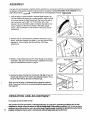
ASSEMBLY
The help of a second person is needed. Set the treadmill in a cleared area and remove all packing materials. Do
not dispose of the packing materials until assembly is completed. TOOLS REQUIRED FOR ASSEMBLY: The
7/32" allen wrench
==.,==,==j
:included
and your own adjustable wrench
1. With the help of a second person, raise the Right Upright (16)
and Left Upright (not shown) to a vertical position. Align the hole
in the lower end of the Right Upright with the hole in the side of
the Frame (45). Insert a 3/8" x 3 1/4" Bolt (20), with a Flat
Washer (19), into the Right Upright and tighten the Bolt into the
Frame. Tighten the Bolt that is already in the Right Upright.
Attach a Bolt and Washer on the left side in the same manner
(not shown).
19
)
2. With the help of a second person, rotate the Handrail (7) up as
shown. Insert two Handrail Lock Bolts (1) into the Left and Right
Uprights (2, 16) and tighten the Bolts with the 7/32" Allen
Wrench (91).
91
1
3. Slide the metal Clothes Clip onto the Pulse Earclip in the indicated location. The use of the Pulse Earclip is explained in the LED
DISPLAY OPERATION section on page 9.
4. Remo_,e the paper backing from the Wrench Clip (68). Press the
Wrench Clip onto the Frame (45) in the indicated location. Press
the 3/16" Allen Wrench (67) into the Wrench Clip.
Make sure that all parts are tightened before using the treadmill.
Note: To protect the floor, a covering should be placed under
the treadmill.
OPERATION
45
AND ADJUSTMENT
PLUGGING IN THE POWER CORD
• "
This product must be grounded. !f. it shou!d_malfunctionor •break down, grounding provides a path of least
_:_.r__f_ectticcurm_ffo-_Cethe
_roduGt
is_pped
With a cord having an
equip_rnent-groundingconductor and a grounding plug. Plug t f_epower cord Into an appropriate outlet that is
6
properly Installed and grounded in accordance withal| Jeeiai _les
and ordinances.
,& D,&NGE R: ,mproper
connection
of the equipment-grounding
conductor can result in a risk of elec-
tric shock. Check with a qualified electrician or serviceman if you are in doubt as to whether the product is properly grounded. Do not modify the plug provided with the product---if it will not fit the outlet, have a proper outlet
installed by a qualified electrician.
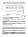
This product is for use on a nominal 120-volt circuit, and has a grounding plug that looks like the plug illustrated in
Drawing 1.
A temporary adapter that looks like the adapter illustrated in Drawing 2 may be used to connect this plug to a 2pole receptacle as shown in Drawing 2 if a properly grounded outlet is not available. The temporary adapter
should be used only until a properly grounded outlet (Drawing 1) can be installed by a qualified electrician. The
green colored rigid ear, lug, or the like extending from the adapter must be connected to a permanent ground
such as a properly grounded outlet box cover. Whenever the adapter is used it must be held in place by a metal
screw.
Some 2-pole receptacle outlet box covers are not grounded. Contact a qualified
the outlet box cover is grounded before using an adapter.
Grounded
Outlet Box
Grounding
electrician
to determine
2
_rounded
Outlet Box
Plug
Grounding
Pin
_rounding
Grounding
Grounded
BREAKING
if
Plug
Pin
Outlet
IN THE MAINTENANCE-FREE
Metal Screw
WALKING PLATFORM
IMPORTANT: This treadmill features a maintenance-free walking platform. After completion of the following
break-in procedure, the walking platform requires no further maintenance: The walking platform must be broken
in completely so that the coating on the walking platform impregnates the walking belt. If this is not done, the
treadmill may function erratically. Follow the steps below to break in the walking platform completely.
1. Adjust the incline of the treadmill to the highest setting. (See pages 8 and 9.)
2. Adjust the speed of the walking belt to about 3 or 4 miles per hour. (See page 8.) Hold the handrail and begin
walking on the treadmill. Be sure to walk on all areas of the walking belt--not only on the center. Continue
for 5to 10 minutes, or until the walking belt no longer slows as you walk.
3. To complete the break-in procedure, first stop the walking belt
and unplug thepower cord. Lift each side of the walking belt
and apply the included lubricant generously to the area of the
walking platform shown at the right. This one-time application
completes the break-in of the maintenance-free walking platform.
IMPORTANT: The included 100% silicone lubricant is specially
formulated for this one-time application. Do not apply any other silicone lubricant or spray. Such substances may damage the walking platform and cause excessivewear or premature failure of the
- .-_eadmilL
Apply lubricantto
entireshaded area.
Note_:_e treadmill may fun=lOn-efrati_'11y dEtringthte:lxeak-in procedure. The walking belt may slowto a stop or
surge in speed, and an error code ("Et:," "L=2,
" "L_," etc.) may appear in the SPEED display. If this happens,
remove the safety key, wait for ten seconds and then re_,sed it.
7
DIAGRAM OF THE CONSOI'E
The heart of the treadmill is the sophisticated console. The console features a safety key-operated power switch,
electronic speed and incline controls and six independent LED displays to give you continuous exercise feedback. Please read these Instructions carefully before operating the console. Note: If there Is a sheet of protective plastic on the face of the console, peel it off before operating the console.
Motivational Fitness Monitor
I
!
Pulse Earclip Jack j
_
Safety Key/Clip
TURNING ON THE POWER
If the safety key is in the console, remove it. Make sure that the on/off switch located
near the power cord is in the ON position (see the drawing at the right). Plug in the
power cord (see PLUGGING IN THE POWER CORD on=pages 6 and 7). All d_splays
and indicators on the console willflash three times.
oNj
Position
Step onto the foot rails of the treadmill. Locate the clip attached by a cord to the safety key, and slide the clip onto
the waistband of your clothing.
_
WAR NING:
Do not stand on the walking belt when turning the power on. Always wear the
clip when operating the treadmill. If you fall, the safety key will be pulled from the console, Instantly turnIng the power off.
Insert the safety key into the console.The six LED displays will light. Note: If the safety key was in the console
when the power cord was plugged in, a "PO" will appear in the speed display. If this occurs, remove the safety
key, wait for ten seconds and then reinsert it.
CONTROLLING
THE SPEED OF THE TREADMILL
When the power is turr_ed on, the walking belt will be stationary. The speed of the walking belt can be controlled
by pressing the SPEED buttons. Each time the SPEED increase button is pressed, the speed will increase by 0.1
mile per hour, beginning at 0.5 miles per hour. Each time the SPEED decrease button is pressed, the speed will
decrease by 0.1 mile per hour. The buttons can be held down to change the speed rapidly. The speed can be set
at a minimum of 0.5 miles per hour, up to a maximum of 10 miles per hour, in increments of 0.1 mile per hour.
WARNING:
A,er
the SPEED buttons are pressed, it will take a few seconds for the walking
belt to reach the selected speed. Adjust the speed gradually until you are familiar
the treadmill.
8
with the operation of
PrOs _SpiEED.ir_r_l_se
buttQn_untilthe wa_
{_elt;beginsto moveat slow speed. H_dthe handrail, step
_=_lly_lldng
_g,:_:4be_)eedas
desired by pressinglhe SPEED but.t_;iT0
stop the waling belt, holddown the SPEED decrease button. The walking belt can be slopped quickly, if
de_ecl_ .b.ypressing the STOP.bar.
CHANGING THE INCLINE OF THE TREADMILL
To vary the intensity of your exercise, the incline of the treadmill can be changed by pressing the INCLINE buttons. Each time one of the buttons is pressed, the incline will change by 1%. The buttons can be held down to
change the incline rapidly. The incline can be set at a minimum of 2%, up to a maximum of 12%. Note: After the
buttons are pressed, it will take a few seconds for the treadmill to reach the selected incline.
LED DISPLAY OPERATION
INCLINE DISPLAY--The
incline display will show the selected incline of the treadmill.
PULSE DISPLAY--To use the pulse display of the console, plug the pulse earclip into the jack on the console.
Attach the earclip to your left ear lobe and slide the metal clothes clip onto your collar. After a few seconds, your
pulse will be shown in the pulse display. If your pulse is not shown, rub your ear lobe and reposition the earclip, tt
may be helpful to stand still while measuring your pulse.
CALORIES DISPLAY--The calories display will show the approximate number of nutritional Calories that you
have burned. Note: The number of Calories burned will vary slightly depending on the sl_eed and incline of the
treadmill.
TIME DISPLAY--This
display shows the elapsed time.
SPEED DISPLAY--This
display shows the current speed of the walking belt.
DISTANCE DISPLAY--The
distance display will show the total distance that you have walked or run, in miles.
Note: To reset the displays, remove the safety key then reinsert it into the console.
INFORMATION
MODE
The console features an information mode to let you keep track of trip time and distance; as well as the total time
and distance that the treadmill has been operated. To select the information mode, hold down the STOP bar
while inserting the safety key into the console.
When the information mode is selected, the time display will show the trip time, up to 9,999 hours. The distance and
speed displays together will show the trip distance, up to 99,999 miles. While the trip time and distance are displayed, they can be reset to zero by pressing the INCLINE decrease button.
To view the total time and distance, press the INCLINE increase button. The time display will show the total time, up
to 9,999 hours. The distance and speed displays together will show the total distance, up to 99,999 miles.
To exit the information mode, remove the safety key.
TURNING OFF THE POWER
To turn off the power, remove the safety key from the console. Store the safety key in a secure location.
9
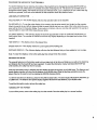
TROUBLE-SHOOTING
Most treadmill problems can be solved by following the simple steps below. Find the symptom that appties,
and follow the steps listed. If further assistance is needed, call our Customer Service Department toll-free at 1800-999-3756, Monday through Friday, 6 a.m. until 6 p.m. Mountain Time.
1. SYMPTOM:
THE POWER DOES NOT TURN ON
a. Make sure that the power cord is plugged into a properly grounded outlet. (See PLUGGING IN THE
POWER CORD on pages 6 and 7.) If an extension cord is needed, use only a 14-gauge general-purpose
cord of five feet or less in length.
°
b. After the power cord has been plugged in, make sure that the safety key is fully inserted into the console.
Various indicators on the console should light. (See TURNING ON THE POWER on page 8.)
C.
d°
Check the circuit breaker located on the treadmill near the
power cord. If the switch protrudes as shown, the circuit breaker has tripped. To reset the circuit breaker, wait for five minutes and then press the switch back in.
Tripped i: _
Reset
Check the ON/OFF switch located on the treadmill near the
power cord. The switch must be in the ON position.
ON J
2. SYMPTOM:
THE POWER TURNS OFF DURING USE
a. Check the circuit breaker located on the treadmill near the power cord. If the circuit breaker has tripped (see
the drawing above.), wait for five minutes and then press the switch back in.
b. Make sure that the power cord is plugged in ....
c. Remove the safety key from the console. Reinsert the safety key fully into the console. Various indicators on
the console should light.
d. Check to make sure the ON!OFF switch is in the ON position. (See 1. d. above.)
e. If the treadmill still will not run, please call our Customer Service Department.
3. SYMPTOM:
THE PULSE EARCLIP DOES NOT FUNCTION PROPERLY
a. Mak_ sure that the pulse earclip is plugged fully into the jack on the console. Rub your left ear lobe and
. reposition the earclip. Attach the clothes clip to your collar.
b. Stand still while measuring your pulse.
c. The _lse earclip may need to be .cleared. Press the earclip open, and find the two clear circles inside the
earclip. Wipe the two clear circles using a cotton swab saturated with denatured alcohol. NOTE: Various factors, including the user's movement, may affect the accuracy of heart rate readings. The earclip is intended
only as an exercise aid in determining heart rate trends in general.
4. SYMPTOM: THE CONSOLE DOES NOT FUNCTION PROPERLY
a. If a console malfunction occurs, an error code ('El ," =E2," "E3," etc.) may appear on the display. If an error
code appears, remove the safety key, wait for ten seconds and then reinsert the safety key. If an error code
appears again, call our Customer Service Department. Do not operate the treadmill until the problem is corrected.
5. SYMPTOM:. THE WALKING BELT SLOWS WHEN WALKED ON
10
_.a._¢_Tffst_ti,,_¥_4amt, he _wal,
k'<_'er'N_s.orface
oflhe waltdng be tt-for 10 m3nutes t° break in
th_waJking platform. During this initial break-in period, it is normal for the walking belt to slow. (See BREAKING IN THE MAINTENANCE-FREE WALKING PLATFORM on page 7.)
b. If an extension cord is needed, use only a 14-gauge general-purpose cord of five feet or less in length.
c. If the walking belt is overtightened, treadmill performance may
decrease and the walking belt may be permanently damaged.
Remove the safety key and UNPLUG THE POWER CORD.
Using the 3/16" allen wrench, turn both rear roller adjustment
bolts counterclockwise, 1/4 of a turn. When the walking belt is
properly tightened, you should be able to lift each side of the
walking belt 3-4 inches off the walking platform. The center of the
walking belt should just touch the walking platform. Be careful to
keep the walking belt centered. Plug in the power cord, insert the
safety key and run the treadmill for a few minutes. Repeat until
the walking belt is properly tightened.
6. SYMPTOM:
THE WALKING
BELT IS OFF-CENTER
Rear Roller
H/
AdjTkstment B°lts
/.@
OR SLIPS WHEN WALKED ON
a. If the walking belt has shifted to the left, first remove the safety
key and UNPLUG THE POWER CORD. Using the 3/16" allen
wrench, turn the left rear roller adjustment bolt clockwise, and
the right bolt counterclockwise, 1/4 of a turn each. Be careful not
to overtighten the walking belt. Plug in the power cord, insert the
safety key and run the treadmill for a few minutes. Repeat until
the walking belt is centered.
a
b. If the walking belt has shifted to the right, first remove the safety
key and UNPLUG THE POWER CORD. Using the 3/16" allen
wrench, turn the left rear roller adjustment bolt counterclockwise,
and the right bolt clockwise, 1/4 of a turn each. Be careful not to
overtighten the walking belt. Plug in the power cord, insert the
safety key and run the treadmill for a few minutes. Repeat until
the walking belt is centered.
c. If the walking belt slips when walked on, first remove the safety
key and UNPLUG THE POWER CORD. Using the 3/16" allen
wrench, turn both rear roller adjustment bolts clockwise, 1/4 of a
turn. When the walking belt is correctly tightened, you should be
able to lift each side of the walking belt 3-4 inches off the walking
platform. The center of the walking belt should just touch the
walking platform. Be careful to keep the walking belt centered.
Plug in the power cord, insert the safety key and run the treadmill
for a few minutes. Repeat until the walking belt is properly tightened.
STORAGE
Unplug the power cord when the treadmill is not in use. Remove the
indicated bolt and washer from the lower end of each upright. Loosen
the other bolts in each upright. Carefully rotate the uprights down. It is
recommended that the treadmill be covered during extended periods
of storage.
:lemove
11
CONDITIONING
GUIDELINES
The following guidelines will help you, to plan your exercise program. Remember
that proper n_dtion and ade-
quate rest are essential for successful results.
WARNING: Before
beginning
thisoranyexercise
program,
consult
yourphysician. Thisis
especially
important
for individuals
over the age of 35 or individuals
with pre-existing
health problems.
EXERCISE INTENSITY
To maximize the benefits of exercising, it is important to exercise with the proper intensity. The proper intensity
level can be found by using your heart rate as a guide. For effective aerobic exercise, your heart rate should be
maintained at a level between 70% and 85% of your maximum heart rate as you exercise. This is known as your
training zone. You can find your training zone in the table below.
AGE
UNCONDITIONED
TRAINING
ZONE
(BEATS/MIN)
CONDITIONED
TRAINING ZONE
(BEATS/MfN)
AGE
UNCONDITIONED
TRAINING
ZONE
(BEATS/MIN)
CONDITIONED
TRAINING ZONE
(BEATS/MI_)
20
138-167
133-162
55
127-155
122-149
25
136-166
132-160
60
126-153
121-147
30
135-164
130-158
65
125-151
119-145
35
134-162
129-156
70
123-15O
118-144
40
132-161
127-155
75
122-147
117-142
45
131-159
125-153
8O
120-146
115-140
50
129-156
124-150
85
118-144
114-139
•
During the first few months of your exercise program, keep your heart rate near the low end of your training zone
as you exercise. After a few months of regular exercise, your heart rate can be increased gradually until it is near
the middle of your training zone as you exercise. You can measure your heart rate using the pulse mode of the
console. Exercise for at least four minutes, and then measure your heart rate immediately. If your heart rate is too
high, decrease the intensity of your exercise, if your heart rate is too low, increase the intensity of your exercise.
A'
IA/A
1-111111#'l_
_wi4.rt
|_1! |_I!L_: The pulse earclip is not a medical device. Various factors, including your movement during exercise, may affect the accuracy of heart rate readings. The earclip is intended only as an
exercise aid in determining heart rate trends in general.
WORKOUT GUIDELINES
Eacll Wo_olA should consist of three_)asic parts: a warm-up, 20 to 30 minutes of training zone exercise, and a
cool-down. Warming up prepares the body for exercise by increasing circulation, delivering more oxygen to the
muscles and raising the body temperature. Begin each workout with 5 to 10 minutes of stretching and light exercise to warm up. Then, increase the intensity of your exercise to raise your heart rate to your training zone for 20
to 30 minutes. Breathe regularly and deeply as you exercise--never hold your breath. Finish each workout with 5
to 10 minutes of stretching to cool down. This will increase the flexibility of your muscles as wellas help to
decrease soreness and other post-exercise problems.
To m&intain or improve your condition, complete three workouts each week, with at least one day of rest between
workouts. After a few months of regular exercise, you may complete up to five workouts each week, if desired.
The key to success is CONSISTENCY.
i2
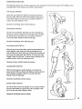
SUGGESTED
STRETCHES
The following stretches can provide a good warm-up or coot-down. Correct form for each stretch is shown in the
drawings below. Move slowly as you stretch--never bounce.
TOE TOUCH STRETCH
Stand with your knees bent slightly and slowly bend forward
from your hips. Allow your back and shoulders to relax as you
reach down toward your toes as far as possible. Hold for 15
counts, then relax. Repeat 3 times.
Stretches: Hamstrings, back of knees and back.
HAMSTRING
STRETCH
Sit with one leg extended. Bring the sole of the opposite foot
toward you and rest it against the inner thigh of your extended
leg. Reach toward your toes as far as possible. Hold for 15
counts, then relax. Repeat 3 times for both legs.
Stretches: Hamstrings, lower back and groin.
CALF/ACHILLES
STRETCH
With one leg in front of the other, reach forward and place your
hands against a wall. Keep your back leg straight and your
back foot flat on the floor. Bend your front leg, lean forward and
move your hips toward the wall. Hold for 15 counts, then relax.
Repeat 3 times for both legs. To cause further stretching of the
achilles tendons, bend your back leg as well.
Stretches: Calves, achilles tendons and ankles.
QUADRlCEPS
STRETCH
With one hand against a wall for balance, reach back and
grasp one foot with your other hand. Bring your heel as close to
your buttocks as possible. Hold for 15 counts, then relax.
Repeat 3 times for both legs.
Stretches: Quadriceps and hip muscles.
INNER THIGH STRETCH
Sit with the soles of your feet together and your knees outward.
Pull your feet toward your groin area as far as possible. Hold
for 15 counts, then relax. Repeat 3 times.
Stretches: Quaddceps and hip muscles.
.
/!i
¸
,,i
13
PART LIST--Model
Key
No.
1
2
3
4
5
6
7
8
9
10
11
12
13
14
15
16
17
18
19
20
21
22
23
24
25
26
27
28
29
30
31
32
33
34
35
36
37
38
39
40
41
42
43
44
45
46"
47
48
49
50
14
No. PFTL10040
R994A
Description
Key
No.
Qty.
Handrail Lock Bolt
Left Upright
3/8" x 1" Bolt
Safety Key/Clip
Handrail Cap
Cage Nut
Handrail
Console Screw
Console
Pulse Earclip/Clothes Clip
51
52
53
54
55
56
57
58
59
60
2
1
1
2
1
2
2
4
4
2
Small Bolt
Incline Optic Disk
Incline Motor Bracket
Incline Motor Bolt
Incline Motor
Incline Motor Spacer
Optic Switch Wire Harness
Endcap Screw
Cushion Foot Bolt
Cushion Foot
1
1
1
1
1
1
1
3
11
Handrail Wire Harness
Front Left Endcap
Front Roller/Pulley
Right Foot Rail
Front Right Endcap
Right Upright
Front Roller Adjustment Bolt
Roller Adjustment Washer
Fiat Washer
61
62
63
64
65
66
67
68
69
1
2
2
4
1
1
1
1
1
Right Rear Endcap
Rear Roller Adjustment Bolt
4" Cable Tie
8" Cable Tie
Tie Block
Tie Block Screw
3/16" Allen Wrench
Wrench Clip
Rear Roller
4
15
1
1
10
2
3/8" x 3 1/4" Bolt
Safety Cover Screw
20" Wire Hamess
Belt Guide
Screw
12" Cable Loom
70
71
72
73
74
75
1
8
1
1
1
1
Left Rear Endcap
Platform Screw
Walking Platform
Left Foot Rail
Motor Swivel Bolt
MBtor Tension Nut
76
77
78
79
80
_
_
83
84
85
86
87
88
89
90
91
92
#
#
#
#
#
#
#
#
1
1
1
2
1
1
1
1
2
1
2
2
1
9
1
1
1
1
1
1
1
1
1
1
1
Qty.
2
1
2
1
2
6
1
6
1
1
1
1
1
1
1
1
1
2
2
1
1
1
6._
3
5
1
1
4
4
1
1
1
1
2
2
14" Power Board-Controller Wire
Choke
Electronics Bracket
Grommet
Circuit Breaker
On/Off Switch
Power Cord
Front Wheel Bolt
Front Wheel
Controller
Power Cord Bracket
Safety Cover Bracket
Wheel Nut/CushionFoot Nut
Incline Leg Bolt/Motor Tension Bolt
Incline Leg Nut/Motor Tension Nut
Incline Leg
Power Board
Power Board Screw
Power Board Spacer
Frame
Front Safety Cover
Back Safety Cover
Walking Belt
Small Nut
Optic Switch
-Note: _#'indicates a_n_n-_uStraled part._pec_cafions
for info_n'_ation
about oi'dering replacement parts.
Description
Motor Mounting Bracket
Pulley/FlywheeVFan
Motor Belt
Motor Bolt
Motor
Speed Optic Disk
Optic Switch Bracket
Optic Switch Bracket Nut
Motor Nut
Wire Cover
Cushion Foot Cover
Deck Shim
Choke Bracket
Small Hex Screw
6" Cable Loom
7/32" Allen Wrench
Cable Tie
8" White Wire, Male/Female
14" White Wire, 2 Female
4" Black Wire, 2 Female
8" Black Wire, 2 Female
8" Green Ground Wire
8" Red Wire, Male/Female
8" Blue Wire, 2 Female
Owner's Manual
are subject to change without notice. See the back cover
EXPLODED
DRAWING--Model
No. PFTL10040
RSS4A
4
10
7
3
2
\
\
5
78
\-
85
79
11
91
8O
82 49
57
3
12
5119
16
2O
17
39
27
88
14 1
19
47
73
46
48
71
/
70
-22
23
25
26
20
6
45
I
24
i
61
60
34
32
19
38
56
39
© 1994 Proform Fitness Products, Inc,, a Subsidiary of Welder Health and Fitness, Inc.
15
ORDERING
REPLACEMENT
PARTS
To order replacement pa,'ls,,catl our Customer- Service Department toll-free at 1-800-999-3756, Monday through
Friday, 6 a.m. until 6 p.m, Mountain Time (excluding holidays). When ordering parts, please be prepared to give
the following information:
1. The MODEL NUMBER of the product (PFTL10040).
2. The NAME of the product (PROFORM ®520 treadmill).
3. The SERIAL NUMBER
of the product (see the front cover of this manual).
4. The KEY NUMBER of the part(s) from page 14 of this manual.
5. The DESCRIPTION
PartNo. 120469 R994A
of the part(s) from page 14 of this manual.
Pdntedin USA