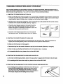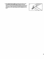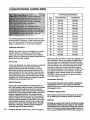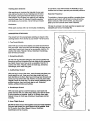
1
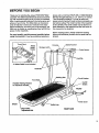
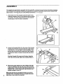
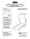
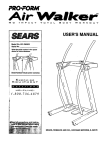
PRO.FORM
SEARS
Model No. 831.297642
Serial No.
The serial number can be found in the
locationshown below. Write the serial
number in the space above.
Number Decal
F____x ===-R
EQUIPMENT
C
i .,5 _-
HELPLINE!
1-800-736.6879
USER'S MANUAL
SEARS, ROEBUCK AND CO., HOFFMAN ESTATES, IL 60179
[
FULL 90 DAY WARRANTY
For 90 days from the date of purchase, if failure occurs due to defect in matedai or workmanship in this
SEARS TREADMILL EXERCISER, contact the nearest SEARS Service Center throughout the United
States and SEARS will repair or replace the TREADMILL EXERCISER, free of charge.
This warranty does not apply when the TREADMILL EXERCISER is used commercially or for rental pup
pot,_o
This warranty gives you specific legal rights, and you may also have other dghts which vary from state
to s_ate.
SEARS, ROEBUCK AND CO., DEPT. 817WA, HOFFMAN ESTATES, IL 60179
2
J
PRO.FORM
TABLE OF CONTENTS
FULL 90 DAY WARRANTY ....................................................................
IMPORTANT PRECAUTIONS .................................................................
2
4
BEFORE YOU BEGIN .......................................................................
• ASSEMBLY ...............................................................................
OPERATION AND ADJUSTMENT
.............................................................
5
6
7
HOW TO FOLD AND MOVE THE TREADMILL ..................................................
TROUBLE-SHOOTING
AND STORAGE ........................................................
CONDITIONING GUIDELINES
...............................................................
ORDERING REPLACEMENT PARTS ..................................................
10
12
14
Back Cover
Note: An EXPLODED DRAWING and a PART LIST are attached to the center of this manual. Save the
EXPLODED DRAWING and PART LIST for future reference.
Read all
3
Usethe_admlll
.... man_a_i
:,9:; When:'c0nn_lng:the
:' TO PLUG IN :
•
plug the
•:.!3_Into a
•
: !,z
11
::.: awayfrom::
12, Never i
: Is turned off.
4
BEFORE YOU BEGIN
Thank you for selecting the unique PROFORM ° 580si
treadmill. The 580si treadmill blends advanced technology with innovative styling to let you enjoy an excellent
form of cardiovascular exemise in the convenience and
privacy of your home. The 580si offers an impressive
array of features to make your workouts more enjoyable and effective. And when you're not exemising, the
580si can be folded up, requiring less than half the floor
space of other treadmills.
For your benefit, read this manual carefully before
using the treadmill. If you have additional questions,
Towel Rack
Water
Bottle*
please call our toll-free HELPLINE at 1-800736-6879,
Monday through Saturday, 7 a.m. until 7 p.m. Central
Time (excluding holidays). To help us assist you,
please note the product model number and serial number before calling. The model number of the treadmill
is 831.297642. The serial number can be found on a
decal attached to the treadmill (see the front cover of
this manual for the location).
Before reading further, please review the drawing
below and familiarize yourself with the parts that are
labeled.
Console
*A Water Bottle is not included
Handrails
Foot Rails
On/Off
Sw'dch
Padded Walking Platform
FRONT
Power Cord
BACK
Incline Leg
Rear Roller
RIGHTSIDE
Adjustment
B_t
5
ASSEMBLY
Two people are required for assembly. Set the treadmill in a cleared area and remove all packing materials.
Do not dispose of the packing materials until assembly is completed. Assembly requires the included 7/32"
allen wrench
_
and your own phillips screwdriver
_
.
1. Firmly hold one of the Uprights (6, 88) with both hands.
Raise the Uprights until the Front Wheels (58) are resting
on the floor. The inset drawing shows how the treadmill
should appear when this step is completed.
88
.
Loosen the Crossbar Bolts (1) in the ends of the Console
Crossbar (9). Pivot the Console (10) to the angle shown.
Look under the Left and Right Console Brackets (3, 36)
and find the two small holes in each end of the Console
Crossbar (9). Tighten Crossbar Screws (84) into all four
holes.
2
Pivot the Console (10) upward until it stops. Using the
7/32" Allen Wrench (89), tighten the Crossbar Bolts (1).
3. Remove the paper bacldng from the Adhesive Clip (26).
Press the Adhesive Clip onto the Frame (49) in the indicated IooatJon.Press the 3/16" Allen Wrench (83) into the
Adhesive Clip. The use of the 3/16" Allen Wrench is described on pages 12and 13.
6
Make sure that all parts am tightened before you use the
treadmill. Note: To protect the floor or carpet from darnage, place a mat under the treadmill
49
OPERATION
THE PERFORMANT
AND ADJUSTMENT
LUBE TM WALKING BELT
Your treadmill features a walking belt coated with
PERFORMANT LUBE TM, a high-performance lubricant.
During the first few hours of use, it is normal for a
small amount of white powder to appear on the foot
rails and the walking platform. The White powder is excess lubricant from the walking belt.
iMPORTANT: Never apply silicone spray or other
substances to the walking belt or the walking platform. They will deteriorate the walking belt and
cause excessive wear.
HOWTO
PLUG IN THE POWER CORD
DANG ER :improper
This product must be grounded. If it should malfunction or break down, grounding provides a path of least
resistance for electric current to reduce the risk of electric shock. This product is equipped with a cord having
an equipment-grounding conductor and a grounding
plug. Plug the power cord into a surge protector,
and plug the surge protector into an appropriate
outlet that is properly Installed and grounded In
accordance with all local codes and ordinances.
This product is for use on a nominal 120-volt circuit,
and has a grounding plug that looks like the plug illus_
trated in drawing 1 below. A temporary adapter that
looks like the adapter illustrated in drawing 2 may be.
used to connect the surge protector to a 2-pole receptacle as shown in drawing 2 if a properly grounded outlet is not available.
connection
of the equipment-grounding
conductor can
result in an Increased risk of electric shock.
Check with a qualified electrician or service. man if you are in doubt as to whether the
product is properly grounded. Do not modify
i the plug provided with the product--if it will
not fit the outlet, have a proper outlet installed by a qualified electrician.
The temporary adapter should be used only until a
properly grounded outlet (drawing 1) can be installed
by a qualified electrician.
The green-colored rigid ear, lug, or the like extending
from the adapter must be connected to a permanent
ground such as a properly grounded outlet box cover.
Whenever the adapter is used it must be held in place
by a metal screw. Some 2-pole receptacle outlet box
covers are not grounded. Contact a qualified electrician to determine If the outlet box cover is
Your treadmill, like any other type of sophisticated
grounded before using an adapter.
electronic equipment, can be seriously damaged by
sudden voltage
changes in your home's
power. Voltage surges,
j Grounded Outlet Box
spikes, and noise interference can result from
weather conditions or
• ./Grounding Pin
from other appliances
Grounding
being turned on or off.
unding Plug
To decrease the possiblllfy of your tread3rounded Outlet
mill being damaged,
always use a surge
protector (not Included) with your
treadmill.
Grounded Outlet Box
Surge protectors are
sold at most hardware
stores and department
stores. Use only a ULlisted surge protector,
rated at 15 amps, with a
14-gauge cord of five
feet or less in length.
Adapter
_
,.Grounding Pin
Plug
Protector
Metal Screw
7
DIAGRAM OF THE CONSOLE
Mode Indicators
: CAUTIO N: Before
Operating the
_=,.c_nso]e, read
the
following
precautions.
,
•
....:....
•.
_ .
: :• ,:
k.:. Do not s_nd
• :|ng
on the
On the walking
....
power;_
.,...
_:.__
..........
.;.
..... ,..
Next, step onto the foot rails of the treadmill. Find the
clip attached to the key (see the drawing above), and
slide the clip onto the waistband of your clothing.
Follow the steps below to operate the console:
the C!lpwhi!e operating the
I
_:_-Al_mys _ar
.
belt wi'mn turn-
the power cord is propedy plugged in. (See HOW TO
PLUG IN THE POWER CORD on page 7.)
_f.l'l,d
I
I
l|lle_
B
.::.," Adjust the sPee_ii'n small Increments.
Insert the key fully into the power switch•
The four displays
and the green MANUAL mode indicator
will light.
> ° To reduce the possibility of eleclflc shock, keep
the console dry. Avoid spilling liquids on the
console, and use only a sealed water bottle.
The training zones marked beside the speed
:._:.,control a m genera ! gu!dellnes only. Se e.. ,:
_ CONDmONING GU!DELINES on page 14_;
_.:_,_::_::::_:,:
_i_::._
::_!:_._!_::
:!......
STEP BY STEP CONSOLE OPERATION
The treadmill console features a manual mode and six
preset workout programs. In the manual mode, the
speed of the walking belt can be changed with the electronic speed control When one of the workout programs
b selected, the console will a_orna_c_ control the
speed as it guides you through an effective workout,
Before operating the
console, make sure
• at _e on_off sw_ch
near _e power co_d
b in the "on"position.
8
If the key is in the console, remove it. Make sore that
B
Reset the speed control and select a speed
setting.
Slide the speed control down to
the 'RESET" position. Note..
Each time the walkino beR Is
atooeed, the speed control
must be moved to the
"RESET" _ositlon before the
walklna belt can be mstsrted.
._t
i)i
m
i
•
ii
ii
,,
• 1 I
If
Next. slide the speed control
upward to select a speed sotltng. Note: If the key was Just
Inserted, or If the walldng belt
was stopped with the
START/STOP button, the
walidng beR will not begin to move yet.
Ilil_
EI_
Pressthedeslred
mode.SELECT
MODE button to select the
B
Follow your progress with the monitor displays.
The four monitor displays provide instant feedback:
When the key is inserted, the console will be in the
MANUAL mode.
If you want to select
one of the six preset
programs, press the
SELECT MODE button. The red PROGRAM A indicator
will light. To select PROGRAM B, C, D, E, or F, repeatedly press the SELECT MODE button.
Note: PROGRAMS A, B, and C are twenty-minute
programs; PROGRAMS D, E, and F are thirtyminute programs. The speed profiles in the center
of the console show how the speed of the walking
belt will change during the programs. During PROGRAM A, for example, the speed will gradually increase during the first ten minutes, and then gradually decrease during the last ten minutes. Each program will begin with a two-minute warm-up period,
and end with a two-minute cool-down period.
B
play--Displays the
approximate oumbers of Calories
and Fat Calories
• TIME display-When the console
is in the manual
mode, the elapsed
time will be shown.
When one of the
preset programs is selected, the time remaining in
the program will be displayed.
Press the START/STOP button.
pIo
After the
START/STOP button
is pressed, the walking belt will begin to
move. Hold the
handrails and carefully begin walking on the walking belt.
If the console is in the manual mode, change the
speed of the walking belt as desired by sliding
the speed control. To stop the walking belt, slide the
speed control to the "RESET" position. The walking
belt can also be stopped by pressing the START/
STOP button; however, this will reset the displays.
If one of the preset programs is selected, the speed
setting you selected will be the minimum speed setting for the program. The speed of the walking belt
will then change automatically dudng the program as
shown by the speed profiles in the center of the console. When the program is completed, the walking
belt will automatically slow to a stop. Note: ff the intensity level of the program is too easy or too difficult,
adjust the speed control to select a new minimum
speed setting. To stop the program temperadly, slide
the speed control to the "RESET" position. To restart
tha program, st=dethe spead control up to the desired
position. To terminate the program before the program is completed, press the START/STOP button. If
you select a different program while a program is
running, the walking belt will slow to a stop.
SPEEO
yOUhave bumed
(see BURNING FAT on page 14). Every seven
seconds, the display will change from one number
to the other (an "F" will appear when the number
of Fat Calories is shown). Note: The actual number of Calories you have burned may differ slightly
from the number shown if the speed or incline is
near the lowest or highest setting.
• SPEED displayJ
Displays the speed
of the walking belt,
in miles per hour
(MPH) or kilometers per hour (KPH).
III
Note: To change
the unit of measurement, hold
down the
START/STOP button while inserting
the key into the console. An "E" (for English system-rages per hour) or "M" (for Metric system-kilometers per hour) will appear in the DISTANCE/PULSE display. Press the SELECT MODE
button to select the desired setting. Remove and
then reinsert the KEY. An MPH or a KPH will appear in the SPEED display to show which unit of
measurement you have selected.
• DISTANCE/
PULSE display-• Displays the distance you have
walked or run. If an
MPH appears in
the SPEED display, the distance will be displayed
in miles, ff a KPH appears, the distance will be displayed in lalometers. This display also shows your
pulse when the pulse sensor is used (see step 6).
9
r_
Measureyour pulse,!f
desired.
To use the
pulse sensor, stand
on the foot
rails and
place your
thumb on
the pulse
sensor as
shown.
B
Change the incline of the treadmill, if desired.
To change the incline, hold down
one of the incline
buttons until the
desired incline is
reached.
O
/iqCUNE
19
When you are finished, remove the key.
Step onto the foot
rails and remove
The pulse sensor is pressure-activated. Fully press
down the pulse sensor. Do not press too hard, or
the circulation In your thumb will be restdcted,
and your pulse will not be detected. Next, slightly
raise your thumb until the heart in the
DISTANCE/PULSE display flashes steadily. Hold
your thumb at this level. After 5 to 10 seconds, your
pulse will be displayed. If the displayed pulse appears to be too high or too low, or if your pulse is
not displayed, lift your thumb off the sensor and
allow the display to reset. Press down again on the
sensor as described above. Make sure that your
thumb is positioned as shown, and that you are applyingthe proper amount of pressure to the pulse
sensor.
Try the sensor several times until you become familiar with it. Remember to stand still while measuring
your pulse.
the key from the
console. Store the
key in a secure
place. In addition,
move the on/off
I
switch to the "off" position. (See the drawing near
the bottom of page 8.)
THE INFORMATION
MODE
The console features an information mode that keeps
track of the total time and distance accumulated on the
treadmill. To access this mode, hold down the
START/STOP button while inserting the key into the
console. The TIME display will show the total time. The
SPEED display will show the total distance (if the total
distance exceeds 999, the thousands and ten thousands digits will be shown in the CAL/FAT CAL display). The DISTANCE/PULSE display will show an "E"
or an "M," indicating miles or kilometers (see SPEED
DISPLAY on page 9). To exit the information mode, remove the key from the console.
HOW TO FOLD AND MOVE THE TREADMILL
HOW TO FOLD THE TREADMILL
FOR STORAGE
Before folding the treadmill for storage, unplug the power
cord. You must be able to safely lift 45 pounds (20 kg) in
order to raise, lower, or move the treadmill.
1. Hold the treadmill firmly with your hands in the locations
shown at the fight. To decrease the possibility of InJury, bend your legs and keep your back stralghL
Raise the treadmill to a vertical position. Make sure to lift
with your legs rather than your back.
10
2. Pivotthetreadmilluntilthe lockingpinsnapsintothe
storagelatch.Usingyourlefthand,liftthestoragelatch.
Raisethetreadmilluntilthe lockingpinsnapsintothe
storagelatch.Makesurethat the lockingpinis inside
the storagelatch,andthat the storagelatchis fully
closed.
Pin
To protect the floor or carpet from damage, place a
mat under the treadmill. Keep the treadmill out of direct sunlight. Do not leave the treadmill in the storage position in temperatures above 85 ° Fahrenheit.
HOW TO MOVE THE TREADMILL
et
Before moving the treadmill, convert the treadmill to the storage position as described on page 10.
1. Hold one console bracket with each hand. Place one foot
on the base crossbar as shown.
_
2. Tilt the treadmill back until it rolls freely on the front
wheels. Carefully move the treadmill to the desired location. To reduce the risk of injury, use extreme caution
while moving the treadmill. Do not attempt to move
the treadmill over an uneven surface.
3. Place one foot on the base crossbar, and carefully lower
the treadmill until it is resting in the storage position.
HOW TO FOLD THE TREADMILL
Console
\\
_
Front W_
\\\
_
Base
ar
b
DOWN FOR USE
1. Hold the upper end of the treadmill with your right hand
as shown. Using your left hand, lift the storage latch.
Pivot the treadmill slightly until the locking pin is out of
the storage latch. Make sure that the storage latch is fully
closed.
Storage Latch __'_
cking Pin
2. Hold the treadmill firmly with both hands, and lower the
treadmill to the floor. To decrease the possibility of Injury, bend your legs and keep your back strelghL
11
TROUBLE-SHOOTING
AND STORAGE
Most treadmill problems can be solved by following the simple steps below. Find the symptom that applies, and follow the steps listed, If further assistance is needed, call our toll-free HELPLINE at 1-800-7366879, Monday through Saturday, 7 a.m. until 7 p.m. Central Time (excluding holidays).
1. SYMPTOM: 1:'PIEPOWER DOES NOT TURN ON
a. Make sure that the power cord is plugged into a surge protector, and that the surge protector is plugged into
a properly grounded outlet. (See HOW TO PLUG IN THE POWER CORD on page 7.) Use only a UL-listed
surge protector, rated at 15 amps, with a 14-gauge cord of five feet or less in length.
b. After the power cord has been plugged in, make sure that the key is fully inserted into the console. Various
indicators on the console should light. (See step 1 page 8.)
c. Check the cimuit breaker located on the treadmill near the
power cord. If the switch protrudes as shown, the circuit
breaker has tripped. To reset the circuit breaker, wait for five
minutes and then press the switch back in.
Tripped
_/
Reset
d. Check the on/off switch located at the front of the treadmill
near the power cord. The switch must be in the "on" position.
"On"
Position
I_'
i
2oSYMPTOM: THE POWER TURNS OFF DURING USE
a. Check the circuit breaker located on the treadmill frame near the power cord. If the circuit breaker has
tripped (see the drawing above), wait for five minutes and then press the switch back in.
b. Make sure that the power cord is plugged in.
c. Remove the key from the console. Reinsert the key fully into the console. (See step 1 on page 8.)
d. Check to make sure that the on/off switch is in the "on"position. (See 1. d. above.)
e. If the treadmill still will not run, please call our toll-free HELPLINE.
3. SYMPTOM: THE WALKING BELT SLOWS WHEN WALKED ON
a. Use only a UL-listed surge protector, rated at 15 amps, with a 14-gauge cord of five feet or less in length.
b. If the walking belt still slows when wa!ked on, please call our toll-free HELPLINE.
4. SYMPTOM:
THE WALKING BELT IS OFF-CENTER
OR SLIPS WHEN WALKED ON
a. If the walking belt has shifted to the left, first remove the key and
UNPLUG THE POWER CORD. Using the 3/16" allen wrench,
turn the left rear roller adjustment bolt clockwise 1/4 of a turn.
Plug In the power cord, Insert the key and run the treadmill for a
few minutes. Repeat until the walking belt is centered.
12
a
"
b. If the walking belt has shifted to the dght, first remove the key
and UNPLUG THE POWER CORD. Using the 3/16" allen
wrench, turn the left rear roller adjustment bolt counterclockwise
114 of a turn. Plug in the power cord, insert the key and run the
treadmill for a few minutes. Repeat until the walking belt is centered.
b
13
CONDITIONING
GUIDELINES
Training Zone (Beats/MIn.)
The following guidelines will help you to plan your exemise program. Remember--these are general guidelines. For more detailed information about exemise,
obtain a reputable book or consult your physician.
EXERCISE INTENSITY
Whether you want to bum fat, strengthen your cardiovascular system, or increase your athletic performance, you can tailor your exercise to your specific
goals. The key to achieving the desired resultsis to exercise with the proper intensity:
Burning Fat
To bum fat effectively, you must exercise at a relatively
low intensity level for a sustained period of time.
Dudng the first few minutes of exercise, your body
uses easily accessible carbohydrate ca/o[ies for energy. Only after the first few minutes of exercise does
your body begin to use stored fat calories for energy.
If your goal is to bum fat, set the speed control on the
console to FAT BURN to help you maintain the proper
intensity level. (See pages 8 and g.)
Aerobic Exercise
If your goal is to strengthen your cardiovascular system, your exercise must be "aerobic: Aerobic exercise
is activity that requires large amounts of oxygen for
prolonged periods of time. This increases the demand
on the heart to pump blood to the muscles, and on the
lungs to oxygenate the blood. The proper intensity
level for aerobic exercise can be found by using your
pulse as a guide. As you exercise, your pulse should
be kept at a level between 70% and 85% of your maximum possible heart rate. This is known as your trainIng zone. You can find your training zone in the table
at the top of this page. Training zones are listed accord'ragto age and physical condition.
14
Dudng the first few months of your exercise program,
Age
Unconditioned
Conditioned
20
138-167
133-162
25
136-166
132-160
30
135-164
130-158
35
134-162
129-156
40
132-161
127-155
45
131-159
125-153
50
129o156
124-150
55
127-155
122-149
60
126-153
121-147
65
125-151
119-145
70
123-150
118-144
75
122-147
117-142
80
120-146
115-140
85
118-144
114-139
keep your pulse near the low end of your training zone
as you exercise. After a few months of regular exercise, your pulse can be gradually increased until it is
near the middle of your training zone as you exercise.
You can measure your pulse using the pulse sensor.
Exercise for about four minutes, and then measure
your pulse immediately. If your pulse is too high or too
low, adjust the intensity of your exercise. It may also
be helpful to set the speed control on the console to
AEROBIC to help you maintain the proper intensity
level. (See pages 8 and 9.)
Performance Training
If your goal is high performance athletic conditioning,
set the speed control on the console to PERFORMANCE to help you maintain the proper intensity level.
(See pages 8 and 9.)
WORKOUT GUIDEUNES
Each workout should include three pads: (1) a warmup, (2) training zone exercise, and (3) a cool-down.
Warm-up
Warming up prepares the body for exercise by Increasing circulation, delivering more oxygen to the muscles
and raisk_gthe body temperature. Begin each workout
with 5 to 10 minutes of stretching and light exercise to
warm up (see SUGGESTED STRETCHES on page 15).
TrainingZoneExercise
Afterwarmingup,increasetheintensityofyourexerciseuntilyourpulseis inyourtrainingzonefor 20 to
60 minutes. (During the first few weeks of your exercise program, do not keep your pulse in your training
zone for longer than 20 minutes.) Breathe regularly
and deeply as you exemise---never hold your breath.
to cool down. This will increase the flexibility of your
muscles and will help to prevent post-exercise problems.
Exercise Frequency
To maintain or improve your condition, complete three
workouts each week, with at least one day of rest between workouts. After a few months, you may complete up to five workouts each week if desired.
Cool-down
Finish each workout with 5 to 10 minutes of stretching
The key to success is to make exercise a regular and
enjoyable part of your everyday life.
SUGGESTED STRETCHES
The correct form for several basic stretches is shown in the
drawings below. Move slowly as you stretch-never bounce.
1. Toe Touch Stretch
Stand with your knees bent slightly and slowly bend forward
from your hips. Allow your back and shoulders to relax as you
reach down toward your toes as far as possible. Hold for 15
counts, then relax. Repeat 3 times. Stretches: Hamstrings,
back of knees and back.
2
2. Hamstring Stretch
Sit with one leg extended. Bring the sole of the opposite foot
toward you and rest it against the inner thigh of your extended
leg. Reach toward your toes as far as possible. Hold for 15
counts, then relax. Repeat 3 times for both legs. Stretches:
Hamstrings, lower back and groin.
3
3. Calf/Achilles Stretch
With one leg in front of the other, reach forward and place your
hands against a wall. Keep your back leg straight and your
back foot fiat on the floor. Bend your front leg, lean forward and
move your hips toward the wall. Hold for 15 counts, then relax.
Repeat 3 times for both legs. To cause further stretching of the
achilles tendons, bend your back leg as well. Stretches:
Calves, achilles tendons and ankles.
4
4, Quadrlceps Stretch
With one hand against a wall for balance, reach hack and
grasp one foot with your other hand. Bdng your heel as close
to your buttocks as possible. Hold for 15 counts, then relax.
Repeat 3 times for both legs. Stretches: Quadriceps and hip
muscles.
5
5. Inner Thigh Stretch
Sit with the soles of your feet together and your knees outward.
Pull your feet toward your groin area as far as possible. Hold
for 15 counts, then relax. Repeat 3 times. Stretches:
Quadriceps and hip muscles.
15
REMOVE THIS EXPLODED DRAWING
AND PART LIST FROM THE MANUAL
Save this EXPLODED DRAWING and PART LIST for future reference.
Note: Specifications are subject to change without notice. For information about ordering replacement
the back cover of this manual.
padS, see
PART LIST--Model
Key
No.
Part
No.
Qty.
1
2
3
4
5
6
7
8
9
10*
11
12
13
14
15
16
17
18
19
20
21
22
23
24
25
26
27
28
29
30
31
32
33
34
35
36
37
38
39
40
41
42
43
44
45
46
47
48
49
50
51
52
53
54
55
56
57
58
119994
013282
127091
013322
119038
127739
126775
128265
128477
127984
105477
127089
126747
117806
126134
013547
122812
014117
100994
120867
127692
120785
107503
117882
100498
016028
120630
054023
127419
119163
126910
127847
128903
109365
015071
126641
112609
014127
124569
124695
126457
113203
126730
013162
129022
127698
127699
127700
NSP
112669
108204
127098
118570
113204
012056
126635
125802
052014
2
8
1
8
1
1
1
2
1
1
2
1
1
2
1
1
1
1
2
1
1
1
1
1
1
2
16
3
4
1
1
1
1
1
4
1
1
5
1
1
1
1
1
22
1
1
1
2
1
2
2
2
2
0
2
2
4
2
No. 831.297642
Description
Crossbar Bolt
Console Bracket Screw
Left Console Bracket
Console Screw
Key/Clip
Left Upright
Wire Harness
Cable Loom
Console Crossbar
Console
Motor Nut
Motor
Pulley/FlywheeVFan
Wheel Bolt
Motor Belt
Motor Tension Bolt
Motor Tension Washer
Motor Tension Star Washer
Motor Bolt
Motor Tension Nut
Front Hood
Motor Mount Bracket
Motor Swivel Bolt
Reed Switch/Wire
Magnet
Adhesive Clip
Screw
Wire Clip
Hood Anchor
OrdOff Switch
Electronics Bracket
Controller
Power Board w/Stand-Off
Choke
Plastic Stand-off
Right Console Bracket
Front Roller Adj. Bolt
Adjustment Washer
Power Cord
Grommet
Safety Cover Wire Harness
Safety Cover Cable Loom
Safety Cover
Safety Cover Screw
Front Roller/PuUey
Walking Platform w/Fastener
Walking Belt w/Fastener
Foot Rail w/Fastener
Frame
Hair Pin Cotter
Cotter Pin
Belt Guide
Upright Pivot Washer
Cable Loom (see 8)
Wheel Nut
Updght Pivot Bolt
Rubber Hood Anchor
Front Wheel
RO198A
Key
No.
Part
No.
Qty.
59
60
61
62
63
64
65
66
67
68
69
70
71
72
73
74
75
76
77
78
79
80
81
82
83
84
85
86
87
88
69
90
91
92
93
94
95
96
97
98
99
100"
101
102
103
#
#
#
#
#
#
#
#
#
013375
114270
126058
127672
013544
014132
013399
052012
012149
126735
128260
119425
114009
125758
126729
105444
127009
128986
123470
119439
125860
116585
127644
100691
126040
013141
016057
116927
109382
127741
045017
125871
110722
126641
112628
013300
126650
126960
111869
126845
014086
127090
128254
128465
013540
127860
124768
107771
102634
109407
112083
114953
124770
127998
1
1
1
1
2
2
2
2
6
1
1
4
4
1
2
1
1
1
1
1
1
8
2
8
1
4
5
2
1
1
1
1
2
1
4
12
4
1
2
1
2
1
1
2
4
12
1
1
1
1
1
1
0
1
Description
Incline Rod Bolt
Incline Motor Spacer
Incline Motor
Incline Rod
Incline Leg Bolt
Incline Leg Washer
Incline Leg Wheel Bolt
Incline Leg Wheel
Incline Leg Nut
Incline Leg
Right Rear Adjustment Bolt
Base Crossbar Nut
Base Crossbar Bolt
Rear Hood
Base Crossbar
Left Rear Adjustment Bolt
Rear Roller
Rear Roller Tension Spring
Spring Sleeve
Roller Tension Nut
Rear Roller Guard
Hood Screw
Guard Spring
Platform Screw
3/16" Allen Wrench
Crossbar Screw
8" Wire Tie
Tie Holder Clamp
Circuit Breaker
Right Updght
7/32" Allen Wrench
Motor Controller Wire
Upright Endcap
Water Bottle Insert
Wheel Spacer
Anchor Screw
Upright Foot
Upright Plug
Crossbar Cage Nut
Safety Cover Grommet
Console Bracket Washer
_ Motor/Pulley/Flywheel/Fan
Speed Control
Crossbar Bracket
Crossbar Screw
Fastener
14" White Wire, 2 Female
8" White Wire, Male/Female
8" Green Ground Wire
4 =Black Wire, 2 Female
8" Blue Wire, 2 Female
14" Blue Wire, 2 Female
8"V_Wr_
_U_ab
(r_us_
User's Manual
* Includes all the pads shown in the the box.
# Indicates a non-illustrated part.
r..A*6UU"U
UMAWINU--MOQel
NO. U31.2_1. _1.2
R01g6A
27
!
97
36
• 11
99
84
1
2
71
47
4O
78
76
79
73
7O
67
8O
68
61
SE /A[RS
Model No. 831.297642
QUESTIONS?
If you find that:
* you need help assembling or
operating the PROFORM ° 580si
treadmill
The model number and serial number of your PROFORM s 580si
treadmill are listed on a decal attached to the frame. See the front
cover of this manual to find the location of the decal.
All replacement parts are available for immediate pumhase or
special order when you visit your nearest SEARS Service Center.
To request service or to order parts by telephone, call the toll-free
numbers listed at the left.
When requesting help or service, or ordering parts, please be prepared to provide the following information:
• The NAME OF THE PRODUCT (PROFORM ®580si treadmill)
• a part is missing
• The MODEL NUMBER OF THE PRODUCT (831.297642)
• or you need to schedule repair
service
• The PART NUMBER OF THE PART (see the EXPLODED
DRAWING and PART LIST attached to the center of this manual)
call our toll-free HELPLINE
1-800-736-6879
• The DESCRIPTION OF THE PART (see the EXPLODED DRAWING and PART LIST attached to the center of this manual)
Monday-Saturday, 7 am-7 pm
Central Time (excluding holidays)
REPLACEMENT
PARTS
If parts become wom and need
to be replaced, call the following
toll-free number
1-800-FON-PART
(1-800-366-7278)
SEARS, ROEBUCK AND CO., HOFFMAN ESTATES, IL 60179 USA
Part No. 127998 F00100AC R0196A
Printed in USA © 1996 Sears, Roebuck and Co.