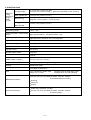
1
MODEL
C 10FC2
POWER TOOLS
C
COMPOUND SAW
C 10FC2
LIST No. E927
TECHNICAL DATA
AND
SERVICE MANUAL
May 1999
SPECIFICATIONS AND PARTS ARE SUBJECT TO CHANGE FOR IMPROVEMENT
REMARK:
Throughout this TECHNICAL DATA AND SERVICE MANUAL, a symbol(s)
is(are) used in the place of company name(s) and model name(s) of our
competitor(s). The symbol(s) utilized here is(are) as follows:
Competitors
Symbols Utilized
Company Name
Model Name
Z
DELTA
36-220
C
MAKITA
LS1040
CONTENTS
Page
[ Business Section ]
1. PRODUCT NAME
• • • • • • • • • • • • • • • • • • • • • • • • • • • • • • • • • • • • • • • • • • • • • • • • • • • • • • • • • • • • • • • • • • • • • • • • • • • • • • • • • • • • • • • • • • • • • • • • • • • • • • • • • • • • • • • • • • • • • • • •
2. MARKETING OBJECTIVE
3. APPLICATIONS
• • • • • • • • • • • • • • • • • • • • • • • • • • • • • • • • • • • • • • • • • • • • • • • • • • • • • • • • • • • • • • • • • • • • • • • • • • • • • • • • • • • • • • • • • • • • • • • • • • • • • • • • • •
1
• • • • • • • • • • • • • • • • • • • • • • • • • • • • • • • • • • • • • • • • • • • • • • • • • • • • • • • • • • • • • • • • • • • • • • • • • • • • • • • • • • • • • • • • • • • • • • • • • • • • • • • • • • • • • • • • • • • • • • • • • • •
1
4. SELLING POINTS
• • • • • • • • • • • • • • • • • • • • • • • • • • • • • • • • • • • • • • • • • • • • • • • • • • • • • • • • • • • • • • • • • • • • • • • • • • • • • • • • • • • • • • • • • • • • • • • • • • • • • • • • • • • • • • • • • • • • • •
4-1. Selling Point Descriptions
5. SPECIFICATIONS
1
• • • • • • • • • • • • • • • • • • • • • • • • • • • • • • • • • • • • • • • • • • • • • • • • • • • • • • • • • • • • • • • • • • • • • • • • • • • • • • • • • • • • • • • • • • • • • • • • • • • • • • •
2
• • • • • • • • • • • • • • • • • • • • • • • • • • • • • • • • • • • • • • • • • • • • • • • • • • • • • • • • • • • • • • • • • • • • • • • • • • • • • • • • • • • • • • • • • • • • • • • • • • • • • • • • • • • • • • • • • • • • • •
4
6. COMPARISONS WITH SIMILAR PRODUCTS
• • • • • • • • • • • • • • • • • • • • • • • • • • • • • • • • • • • • • • • • • • • • • • • • • • • • • • • • • • • • • • • • • • • • • • • • • • • •
5
• • • • • • • • • • • • • • • • • • • • • • • • • • • • • • • • • • • • • • • • • • • • • • • • • • • • • • • • • • • • • • • • • • • • • • • • • • • • • • • • • • • •
6
• • • • • • • • • • • • • • • • • • • • • • • • • • • • • • • • • • • • • • • • • • • • • • • • • • • • • • • • • • • • • • • • • • • • • • • • • • • • • • • • • • • • • • • • • • • • • • • • • • • • • • • • • • • • • • • • • •
6
7. PRECAUTIONS IN SALES PROMOTION
7-1. Instruction Manual
8. ADJUSTMENT AND OPERATIONAL PRECAUTIONS
• • • • • • • • • • • • • • • • • • • • • • • • • • • • • • • • • • • • • • • • • • • • • • • • • • • • • • • • • • • • • • •
8
• • • • • • • • • • • • • • • • • • • • • • • • • • • • • • • • • • • • • • • • • • • • • • • • • • • • • • • • • • • • • • • • • •
8
• • • • • • • • • • • • • • • • • • • • • • • • • • • • • • • • • • • • • • • • • • • • • • • • • • • • • • • • • • • • • • • • • • • • • • • • • • • • • • • • • • • • • • • • • • • • • • • • • • • • • •
8
• • • • • • • • • • • • • • • • • • • • • • • • • • • • • • • • • • • • • • • • • • • • • • • • • • • • • • • • • • • • • • • • • • • • • • • • • • • • • • • • • • • • • • • • • • • • • • • • • • • • • • • • • • • • • • • • • • •
9
8-1. Confirmation of Saw Blade Lower Limit Positioning
8-2. How to Use the Vise Ass’y
8-3. Cutting Operation
9. ADJUSTMENT OF COMPONENTS
• • • • • • • • • • • • • • • • • • • • • • • • • • • • • • • • • • • • • • • • • • • • • • • • • • • • • • • • • • • • • • • • • • • • • • • • • • • • • • • • • • • • • • • • • • •
11
• • • • • • • • • • • • • • • • • • • • • • • • • • • • • • • • • • • • • • • • • • • • • • • • • • • • • • • • • • • • • • • • • • • • • • • • • • • • • • • • • • • • • • • • • • • • • • • • • • • • • • • • • •
11
• • • • • • • • • • • • • • • • • • • • • • • • • • • • • • • • • • • • • • • • • • • • • • • • • • • • • • • • • • • • • • • • • • • • • • • • • • • • • • • • • • • • • • • • • • • • • • • • • • • • • • • • • • • • • • • • • • • • • • • • • • • • • • •• • •
11
9-1. Bevel Angle Adjustment
10. PACKING
1
[ Service Section ]
11. PRECAUTIONS IN DISASSEMBLY AND REASSEMBLY
• • • • • • • • • • • • • • • • • • • • • • • • • • • • • • • • • • • • • • • • • • • • • • • • • • • • • • • • •
12
11-1. Disassembly
• • • • • • • • • • • • • • • • • • • • • • • • • • • • • • • • • • • • • • • • • • • • • • • • • • • • • • • • • • • • • • • • • • • • • • • • • • • • • • • • • • • • • • • • • • • • • • • • • • • • • • • • • • • • • • • • • • • • • • • •
12
11-2. Reassembly
• • • • • • • • • • • • • • • • • • • • • • • • • • • • • • • • • • • • • • • • • • • • • • • • • • • • • • • • • • • • • • • • • • • • • • • • • • • • • • • • • • • • • • • • • • • • • • • • • • • • • • • • • • • • • • • • • • • • • • • •
18
11-3. Wiring Diagram
• • • • • • • • • • • • • • • • • • • • • • • • • • • • • • • • • • • • • • • • • • • • • • • • • • • • • • • • • • • • • • • • • • • • • • • • • • • • • • • • • • • • • • • • • • • • • • • • • • • • • • • • • • • • • • • • • • • •
11-4. Lead Wire Precautions
11-5. No-load Current
• • • • • • • • • • • • • • • • • • • • • • • • • • • • • • • • • • • • • • • • • • • • • • • • • • • • • • • • • • • • • • • • • • • • • • • • • • • • • • • • • • • • • • • • • • • • • • • • • • • • • • • •
19
• • • • • • • • • • • • • • • • • • • • • • • • • • • • • • • • • • • • • • • • • • • • • • • • • • • • • • • • • • • • • • • • • • • • • • • • • • • • • • • • • • • • • • • • • • • • • • • • • • • • • • • • • • • • • • • • • • • •
20
11-6. Reassembly Requiring Adjustment
11-7. Lubrication
19
• • • • • • • • • • • • • • • • • • • • • • • • • • • • • • • • • • • • • • • • • • • • • • • • • • • • • • • • • • • • • • • • • • • • • • • • • • • • • • • • • • • • • • • •
20
• • • • • • • • • • • • • • • • • • • • • • • • • • • • • • • • • • • • • • • • • • • • • • • • • • • • • • • • • • • • • • • • • • • • • • • • • • • • • • • • • • • • • • • • • • • • • • • • • • • • • • • • • • • • • • • • • • • • • • • • • • •
21
11-8. Product Precision
12. REPAIR GUIDE
• • • • • • • • • • • • • • • • • • • • • • • • • • • • • • • • • • • • • • • • • • • • • • • • • • • • • • • • • • • • • • • • • • • • • • • • • • • • • • • • • • • • • • • • • • • • • • • • • • • • • • • • • • • • • • • •
21
• • • • • • • • • • • • • • • • • • • • • • • • • • • • • • • • • • • • • • • • • • • • • • • • • • • • • • • • • • • • • • • • • • • • • • • • • • • • • • • • • • • • • • • • • • • • • • • • • • • • • • • • • • • • • • • • • • • • • • • • • •
22
13. STANDARD REPAIR TIME (UNIT) SCHEDULES
• • • • • • • • • • • • • • • • • • • • • • • • • • • • • • • • • • • • • • • • • • • • • • • • • • • • • • • • • • • • • • • • • • • • • •
26
[ Appendix ]
Assembly Diagram for C 10FC2
• • • • • • • • • • • • • • • • • • • • • • • • • • • • • • • • • • • • • • • • • • • • • • • • • • • • • • • • • • • • • • • • • • • • • • • • • • • • • • • • • • • • • • • • • • • • • • • • • • • •
27
1. PRODUCT NAME
Hitachi Compound Saw, Model C 10FC2
2. MARKETING OBJECTIVE
The Model C 10FC2 was developed to upgrade and replace the current Model C 10FC. The major difference
between new model and current one is that the new model has a convenient miter angle setting mechanism for
quick and easy. Only rotate the miter handle to clockwise which is equipped with the turn table, miter angle can
be set (up to 60 right and 45 left). Of course, there are 10 positive miter stops: 0 , 15 , 22.5 , 31.6 , 45 (right
and left), and 60 (right) as well as current Model C 10FC. The basic structure of the product is the same as that
of the Model C 10FC.
3. APPLICATIONS
Cutting various types of wood workpieces
Cutting workpieces of plywood, decoration panels, soft fiverboard and hardboard
Cutting aluminum sashes
4. SELLING POINTS
(4)
Compound miter and
left bevel cutting
(6)
Lightweight design:
14.5 kg
(1)
Press cutting
(5)
(3)
Left bevel cutting
Equipped with debris guard
to restrict dispersion of chips
for enhanced safety in
operation
Right
Left
(2)
Miter cutting
Convenient miter with
angle setting mechanism
(Note) Numerals in ( ) are identical with item numbers in "4-1. Selling Point Descriptions"
--- 1 ---
4-1. Selling Point Descriptions
(1) Press cutting
Table 1
Maker
model
(Unit: mm)
HITACHI
C 10FC2
Max. cutting
dimension
Width (W)
Workpiece
Height (H)
67 x 146
(2-5/8" x 5-3/4")
89 x 92
(3-1/2" x 3-5/8")
with aux. board width
17 mm (11/16")
Height x Width
(H x W)
Fig. 1
Press cutting with the head swiveling enables cutting square workpieces as large as shown in Table 1 in a single
sawing operation. (See Fig. 1)
(2) Miter cutting facility
Table 2
Maker
model
(Unit: mm)
HITACHI
C 10FC2
Max. cutting
dimension
Right 60
Height x Width
(H x W)
Width (W)
Height (H)
70 x 73
(2-3/4" x 2-7/8")
Workpiece
Right and left 45
Height x Width
(H x W)
45 right and
left (60 right)
70 x 89
(2-3/4" x 3-1/2")
Fig. 2
By tuning the table to the right or left as desired, the Model C 10FC2 is capable of miter cutting of up to 45 to the
left, or 60 to the right. The miter angle setting mechanism enables easy cutting-angle setting.
(3) Left bevel cutting facility
Table 3
Maker
model
Max. cutting
dimension
Left bevel 45
Height x Width
(H x W)
(Unit: mm)
Width (W)
(Left)
45
HITACHI
C 10FC2
Height (H)
44 x 130
(1-3/4" x 5-1/8")
By inclining the saw blade section (head) on its swivel mounting, bevel
cutting of up to a maximum of 45 to the left can be obtained. (When
Bevel cutting
the machine is shipped from the factory, the swivel stoppers of the
head are precisely adjusted for 0 and 45 [for further details, please
refer to Paragraph 9-1, Bevel Angle Adjustment.
--- 2 ---
Fig. 3
(4) Compound cutting through use of miter and bevel cutting functions
Table 4
Maker
model
Max. cutting
dimension
(Unit: mm)
Left)
45 (
HITACHI
C 10FC2
Width (W)
Height (H)
Left bevel 45
Right/Left miter 45
Height x Width
(H x W)
45
(Right or left)
44 x 89
(1-3/4" x 3-1/2")
By turning the table to the right or left and inclining the saw
* When the saw blade section (head) is inclined 45 to the
left, the maximum possible angle setting of the table is
restricted to 45 to either the left or right.
Fig. 4
blade section (head) to the left, the Model C 10FC2 is
capable of compound cutting (bevel and miter, see Fig.4) of
workpieces with the maximum dimension shown in Table 4.
(5) Equipped with debris guard to restrict dispersion of chips for enhanced safety in operation.
A debris guard has been adopted to prevent wood chips from adhering to the saw blade at the end of the
cutting operation. The debris guard tilts together with the saw blade during bevel cutting, thereby enhancing
safe operation.
(6) Lightweight design
14.5 kg in weight, for easy transport in a workshop
--- 3 ---
5. SPECIFICATIONS
Maximum
cutting
dimensions
Height x
Width
(H x W)
0 (Right angle)
67 mm (2-5/8") x 146 mm (5-3/4")
89 mm (3-1/2") x 92 mm (3-5/8") [with aux. board width 17 mm (11/16")]
Miter right/left 45
70 mm (2-3/4") x 89 mm (3-1/2")
Bevel left 45
44 mm (1-3/4") x 130 mm (5-1/8")
[Right 60 : 10 mm (2-3/4") x 73 mm (2-7/8")]
Miter right/left 45
+
Bevel left 45
44 mm (1-3/4") x 89 mm (3-1/2")
Miter cutting ranges
Right 0 --- 60 , Left 0 --- 45
Bevel cutting range
Left 0 --- 45
Compound (miter + bevel) cutting
ranges
Miter: right and left 0 --- 45 , Bevel: left 0 --- 45
Angle stopper positions
Right and left 0 , 15 , 22.5 , 31.6 , 45 , Right 60
Applicable saw blade
255 mm (10") external dia. x 15.9 mm (5/8") bore
Power source type and voltage
AC single phase 60 Hz, 115 V
Type of motor
AC single phase commutator series motor
Full-load current
15 A (115 V)
No-load rotation speed
4,900 /min
Max. output
2,200 W
Main body dimensions
(Width x Depth x Height)
535 mm x 600 mm x 489 mm
(21-1/16" x 23-1/2" x 19-1/4")
Weight
14.5 kg (32 lbs), gross weight 22.3 kg (49 lbs)
Coating
Metallic silver green
Packaging
Corrugated cardboard box
Cord
Type: 2-Conductor cabtire cable
Length: 2.4 m (7.8 ft)
Nominal cross-sectional area: 2 mm2
External dia: 9 mm with mold plug
255 mm (10") TCT saw blade (24 teeth, Code No. 790004)
for wood and aluminum cutting
Dust bag
Vise ass'y
Wrench
• • • • • • • • • • • •
Standard accessories
Optional accessories
Holder ass'y (Code No. 311495)
255 mm (10") TCT saw blade (70 teeth, Code No. 976473)
for normal cutting
• • • • • • • • • • • •
--- 4 ---
6. COMPARISONS WITH SIMILAR PRODUCTS
Maker/Model
Item
0 (Right angle)
HITACHI
C 10FC2/C 10FC
Z
C
67 mm x 146 mm
(2-5/8" x 5-3/4")
89 mm x 92 mm
(3-1/2" x 3-5/8")
[with aux. board width
17 mm (11/16")]
70 mm x 146 mm
(2-3/4" x 5-3/4")
69 mm x 130 mm
(2-3/4" x 5-1/8")
70 mm x 105 mm
(2-3/4" x 4-1/8")
69 mm x 92 mm
(2-3/4" x 3-1/8")
44 mm x 130 mm
(1-3/4" x 5-1/8")
44 mm x 146 mm
(1-3/4" x 5-3/4")
35 mm x 130 mm
(1-3/8" x 5-1/8")
44 mm x 89 mm
(1-3/4" x 3-1/2")
44 mm x 105 mm
(1-3/4" x 4-1/8")
35 mm x 92 mm
(1-3/8" x 3-5/8")
70 mm x 89 mm
(2-3/4" x 3-1/2")
Max.
Miter right/left 45
cutting
dimensions
Height
x Width
(H x W) Bevel left 45
Miter right/left 45
+
Bevel left 45
Right 60
70 mm x 73 mm
(2-3/4" x 2-7/8")
Miter cutting ranges
Right 0 --- 60
Left 0 --- 45
Bevel cutting ranges
Left 0 --- 45
Right and left 0 --- 45
Left
0 --- 45
Right 0 --- 52
Left 0 --- 45
Left
0 --- 45
Compound (miter + left bevel)
cutting ranges
Miter: Right and left
0 --- 45
Bevel: Left 0 --- 45
Miter: Right and left
0 --- 45
Bevel: Left 0 --- 45
Miter: Right and left
0 --- 45
Bevel: Left 0 --- 45
Angle stopper position
Right and left 0 , 15 ,
22.5 , 31.6 , 45
Right 60
Right and left 0 , 15 ,
22.5 , 30 , 45
Right and left 0 , 15 ,
22.5 , 30 , 45
Right 52
255 (10")
255 (10")
255 (10")
15 (115 V)
15 (115 V)
15 (115 V)
No-load revolution (/min)
4,900
4,900
4,600
Max. output (W)
2,200
---
---
Insulation structure
Double insulation
Double insulation
Double insulation
Base size
Width x Depth (mm)
525 x 150
(20-11/16" x 5-29/32")
455 x 125
(17-15/16" x 4-15/16")
460 x 135
(18-3/32" x 5-5/16")
Provided (fixed)
Non
Non
300 x 190
(11-13/16" x 7-15/32")
300 x 190
(12-19/32" x 7-15/32")
300 x 150
(11-13/16" x 5-15/16")
535 x 600 x 489
(21-1/16" x 23-1/2" x 19-1/4")
455 x 595 x 535
(17-29/32" x 23-13/32" x 21")
476 x 530 x 532
(18-3/4" x 20-7/8" x 20-15/16")
14.5 (32 lbs)
22 (49 lbs)
11 (24.2 lbs)
Saw blade outer diameter (mm)
Motor
Full-load current (A)
Debris guard
Dust bag size (mm)
Main unit dimensions
Width x Depth x Height (mm)
Product weight (kg)
--- 5 ---
Maker/Model
Item
HITACHI
C 10FC2/C 10FC
Standard accessories
255 mm (10") TCT
saw blade (24 teeth)
for wood and
aluminum cutting
Dust bag
Vise ass'y
Wrench
Optional accessories
Holder ass'y
255 mm (10") TCT
saw blade (70 teeth)
for normal cutting
Z
255 mm (10")
combination saw blade
(104 teeth)
Dust bag
Vise ass'y
(horizontal type)
Holder ass'y
Wrench
C
255 mm (10") TCT
saw blade
Dust bag
Auxiliary plate
13 mm socket wrench
Wrench
Triangular rule
Safety goggles
7. PRECAUTIONS IN SALES PROMOTION
In the interest of promoting the safest and most efficient use of the Model C 10FC2 Compound Saw by all of our
customers, it is very important that at the time of sale the salesperson carefully ensures that the buyer seriously
recognizes the importance of the contents of the Instruction Manual, and fully understands the meaning of the
precautions listed on the various Caution Plates attached to each machine.
7-1. Instruction Manual
Although every effort is made in each step of design, manufacture and inspection to provide protection against
safety hazards, the dangers inherent in the use of any power saw cannot be completely eliminated. Accordingly,
general precautions and suggestions for the use of electric power tools, and specific precautions and suggestions
for the use of the compound saw are listed in the Instruction Manual to enhance the safe, efficient use of the tool
by the customer. Salespersons must be thoroughly familar with the contents of the Instruction Manual to be able
to offer appropriate guidance to the customer during sales promotion.
--- 6 ---
(1) Precautions on the Name Plate
Each Model C 10FC2 is furnished with a Name Plate that lists the following precautions.
CAUTION
For safe operation, see instruction manual.
Do not expose to rain or use in damp locations.
Instruct the customer to thoroughly read the Instruction Manual prior to attempting to operate the machine.
(2) Waring Label (A)
The Warning Label (A) specified by the UL is affixed
WARNING
For Your Own Safety Read Instruction
Manual Before Operating Miter Saw.
on the upper righthand portion of the base. Please
1. Wear eye protection.
2. Keep hands out of path of saw blade.
3. Do not operate saw without guards in place.
4. Do not perform any operation freehand.
5. Never reach around saw blade.
6. Turn off tool and wait for saw blade to stop
before moving workpiece or changing settings.
7. Disconnect power before changing blade or servicing.
8. Saw blade diameter is 10" (255 mm).
H393374
9. No load speed is 4900 rpm.
instruct users to strictly observe the contents in 1 to 9
in the Warning Label (A) shown at left.
(3) Warning Lavel (B)
The Warning Label (B) is affixed on the front left side
WARNING
Link
of the blade guard (metal).
Make sure that link is
securely placed before
operation.
Read instruction manual
carefully to place
the link.
The link indicated here is removed at the time of
shipment from the factory. Please instruct users to
install the link as shown in the Warning Lavel (B) at
left to ensure smooth movement of the blade guard
H391362
(plastic) before putting the tool into use.
(4) Warning Lavel (C)
WARNING
1. Only operate the tool after ensuring
the workpiece is fixed properly with
vise assembly.
2. Never remove guard (including link,
blade guard (metal), vlade guard
(plastic), plate and so on) from the tool
body when you operate it.
The Warning Label (C) is affixed on the rear face of the blade guard (metal).
Please instruct users to strictly observe the contents in 1 and 2 on the Warning Label (C).
--- 7 ---
H393377
8. ADJUSTMENT AND OPERATIONAL PRECAUTIONS
8-1. Confirmation of Saw Blade Lower Limit Positioning
10 mm Depth
adjustment
screw
The lower limit of the saw blade cutting depth is factory-adjusted
so that when the saw blade is fully lowered, its cutting edge is
24 mm to 29 mm (1" to 1-1/8") below the upper surface of the
10 mm
Lock nut
table insert. Lower the saw blade and confirm that it stops at the
correct position.
If it is necessary to adjust the saw blade lower limit, loosen the
10 mm lock nut on the 10 mm depth adjustment screw, and turn
the 10 mm depth adjustment screw if necessary. (See Fig.5)
Fig. 5
[Caution] Perform the adjustment carefully to ensure that the saw blade does not cut into the table. Also,
on completion of adjustment, ensure without fail that the 10 mm lock nut is securely tightened.
8-2. How to Use the Vise Ass'y
Knob
(1) The vise ass'y can be mounted on the left side of the
Vise ass'y
base, and can be raised or lowered according to the
height of workpiece.
1 Insert the support of the vise ass'y into the hole
located on the front of the base.
2 Then tighten the 5 mm wing bolt, as shown in Fig. 6.
3 Turn the knob to thoroughly clamp the workpiece.
Support
[NOTE] The support has two locking grooves into which
Groove
Base
5 mm
Wing bolt
the tip of the 5 mm wing bolt is designed to fit, to
Fig. 6
lock the vise ass'y in the desired position.
Knob
(2) The vise ass'y can be mounted on either the left side
fence or the right side fence, and can be raised or
Fence
Vise ass'y
lowered according to the height of the workpiece.
5 mm
Wing bolt
1 Insert the support of the vise ass'y into the hole
located on either the left side fence or the right side
fence.
2 Then tighten the 5 mm wing bolt, as shown in Fig. 7.
3 Turn the knob to thoroughly clamp the worikpiece.
Fig. 7
[Caution] Always confirm that the motor head does not contact the vise ass'y when it is lowered for
cutting. If there is any danger that it may do so, loosen the 5 mm wing bolt slightly and move
the vise ass'y to a position where it will not contact the saw blade.
Also, always confirm that the vise ass'y is mounted on the right side fence before using the saw
for compound cutting operations (miter + bevel cutting).
--- 8 ---
8-3. Cutting Operation
(1) Cutting efficiency will be reduced if a dull saw blade is used, if an excessively long extension cord id used, or if
the wire gauge of the extension cord is too small. (For details on extension cords, please refer to the
Instruction Manual.) This is particularly important when cutting materials with dimensions which are at or near
the maximum capacity for the machine.
(2) The customer should be advised to thoroughly inspect the workpiece to ensure that there are no metallic
objects (nails in particular), sand, or other foreign matter in or on the workpiece. Saw blade contact with such
foreign matter will not only shorten the service life of the saw blade, but could cause serious accident. Should
the saw blade tips be broken off, the tips may fly toward the operator.
(3) Press cutting
Like Model C 10FC can be used for press cutting of workpieces up to 67 mm x 146 mm (2-5/8" x 5-3/4") in a
single operation by simply pushing the saw blade section (head) downward. The customer should be
cautioned that excessive pressure on the handle will not increase the cutting speed. On the contrary,
excessive pressure may result in reduced cutting efficiency (irregular or rough cutting of the workpiece), and
could also cause overload and subsequent burnout of the motor.
On completion of the cutting operation, turn the switch OFF and wait for the saw blade to come to a complete
stop before raising the saw blade section (head) to its original position. Raising the saw blade section (head)
while the saw blade is rotating may cause unwanted cutting marks on the workpiece.
Techniques to avoid unwanted cutting marks
Uneven and unwanted cutting marks can be avoided throughout the cutting operation by gently and smoothly
pressing down on the handle, so that the entire cutting operation is accomplished in a single uninterrupted
motion.
(4) Miter cutting
Miter cutting is accomplished by turning the table. (For details, please refer to the Instruction Manual.)
(5) Bevel cutting
Bevel cutting of 0 --- 45 to the left is accomplished by inclining the saw blade section (head). (For details,
please refer to the Instruction Manual.)
[Caution] When the workpiece is secured on the left side, the
Fixed-side workpiece
cut-off portion comes to rest on the side of the saw
Cut-off-side
workpiece
blade as illustrated in Fig. 8. If the handle is raised
before the saw blade rotation comes to a complete
stop, there is a chance that the cut-off portion of the
workpiece could become jammed against the saw
blade, causing a hazardous condition. Instruct the
customer to ensure without fail that the saw blade
comes to a complete stop before attempting to raise
the handle.
--- 9 ---
Saw blade
Fig. 8
(6) Compound (miter + bevel) cutting
Compound cutting can be accomplished by combining the miter cutting and bevel cutting operations described
in paragraphs (4) and (5) above. (For details, please refer to the Instruction Manual.)
When the saw blade section (head) is inclined 45 to the left, the table can be turned up to 45 to the right and
left.
(7) Cut surface quality during miter/bevel cutting
The quality of the cut surface depends on the type of
[Miter cutting]
cutting operation (miter or bevel), the type and
A
B
B
A
sharpness of the saw blade, whether the workpiece
is cut to the right or left, and various other factors. In
miter and bevel cutting in particular, cutting is
performed across the wood grain, so the condition of
the cut surface depends on whether the wood is cut
Better
Better
with or against the grain. This is the sames as when
using electric portable planers. Customers should
[Left bevel cutting]
B
A
be advised of these phenomena so that they
understand that in cases when the cut surface may
not be as smooth as expected or hoped for, it is not
caused by the performance of the saw blade or the
Model C 10FC2.
Better
In the cutting examples illustrated in Fig. 9, the cut
Fig. 9
surfaces on the sides marked A are better than
those on the sides marked B .
--- 10 ---
9. ADJUSTMENT OF COMPONENTS
9-1. Bevel Angle Adjustment
When shipped from the factory, the heights of 6 mm
bolt (A) and 6 mm bolt (B) are adjusted so that the saw
blade section (head) will stop at 0 (right-angle) and 45
to the left. To change the head stop positions, instruct
the customer to adjust the height of 6 mm bolt (A) and
6 mm bolt (B) as described below.
6 mm
Lock nut
As illustrated in Fig. 10 and Fig. 11, adjustment of the
bevel angle can be accomplished by loosening the 6
mm nut (lock nut) and turning 6 mm bolt (A) or 6 mm
6 mm
Bolt (A)
(stopper for 0 )
Fig. 10
bolt (B) to raise it or lower it by an appropriate
dimension to change the position at which it comes in
contact with angle regulator.
[Caution] On completion of adjustment, ensure that
the 6 mm nut (lock nut) is securely
Handle
table
support
6 mm Bolt (B)
(stopper for left
45 bevel angle)
tightened.
Adjustment of the squareness of the saw blade with
6 mm
Lock nut
relation to the table can also be accomplished by
adjusting the stopper bolts as described above.
Fig. 11
10. PACKING
The main body of the Model C 10FC2 is sandwiched between packing (A) and packing (B) made of styrofoam.
This system makes the packaging work easier.
(1) Preparation
Remove the vise ass'y, and remove the dust bag from the main unit. Remove the truss hd. screw (1/4" x 1/2")
which fixes the link to the angle regulator and set the link free. Mount the truss hd. screw (1/4" x 1/2") to the
angle regulator again. Then swivel the table through 60 toward the right. Fix the angle regulator securely
with the handle table support. Position the handle table support vertically to keep it from contact with packing
(A) when putting the main unit on packing (A). Push down the head section and move the lock plate to the
lock position to secure the head section in the lower position.
(2) How to install packing (A)
Put packing (A) in the carton box.
Put the main unit in packing (A).
(3) How to install packing (B)
Put packing (B) on the main unit. Put the vise ass'y and the dust bag in the carton box on top of packing (B).
Close the lids of the carton box and bind them together.
--- 11 ---
11. PRECAUTIONS IN DISASSEMBLY AND REASSEMBLY
11-1. Disassembly
Special attention in disassembly should be given to the following items.
The circled numbers in the following figures and the [Bold] numbers in the descriptions below correspond to the
item numbers in the Parts List and the exploded assembly diagram.
Be sure to first disconnect the power plug when performing disassembly and replacement of the saw blade.
Item
No.
1
Disassembly
spots
Disassembly procedure
Necessary tools
Link
17
Blade guard
18
8
19
7
15
6
16
5
2
1
3
4
23
10
9
13
22
14
24
25
26
21
20
702
12
28
27
13
11
701
Fig. 12
1. Remove the Truss Hd. Screw 1/4" x 1/2" [1] and then remove the
Link [2].
Phillips
Screwdriver
2. Remove the Machine Screw M5 x 16 [3] and remove the washer
3/16" x 3/4" [4], the Collar [5], the Guard Retainer [6], the Blade
Guard (Plastic) [7] and the Spring Guard [8].
3. Loosen the Flat Hd. Screw 32 UNF x 13/16" [20] and rotate the
Cutter Shaft Guard [28] until the Bolt (Left Hand) W/Washer M8 x
20 [11] can be seen.
4. Put the Wrench [701] on the Bolt (Left Hand) W/Washer M8 x 20
Wrench
[11] and turn the Wrench [701] until the Bracket Stop [25] is
aligned with the groove of the Shaft Arbor [112] (See Fig. 16)
while pushing the Bracket Stop [25].
Then, loosen the Bolt (Left Hand) W/Washer M8 x 20 [11] and
remove the Bolt (Left Hand) W/Washer M8 x 20 [11], the Washer
[12], the outside Arbor Collar [13], the TCT Saw Blade [702] and
the inside Arbor Collar [13].
5. Remove the three Hex. Socket Hd. Bolts M5 x 20 [14] and the
Blade Guard (Metal) [19].
--- 12 ---
4 mm Hex. bar
wrench
Item
No.
2
Disassembly
spots
Disassembly procedure
Necessary tools
Switch
80
Motor ass'y
81
36
34
35
76
7
33
78
83
82
79
77
6
101
32
29
30
31
37
38
41
84
85
88
86
87
90
91
92
89
93
100
99
94
95
96
97
98
Fig. 13
1. Remove the two Tapping Screws (W/Washers) D5 x 20 [95] at the
right and the two Machine Screws M4 x 20 [100]. Remove the
Phillips
Screwdriver
Handle (Right) [99] from the Handle (Left) [97] with the Switch [91]
mounted.
2. Remove the two Truss Hd. Tapping Screws D4 x 12 [90] which fix
the Switch [91] to the Handle (Right) [99], and remove the Switch
[91].
3. Disconnect the internal wires of the Cord [83] and the Stator [129]
(See Fig. 16) from the Switch [91].
4. Remove the two Tapping Screws (W/Washers) D5 x 20 [95] at the
left to remove the Handle (Left) [97].
5. Remove the Chuck Nut M16 [30] by turning it with a 24 mm
wrench. Pull out the Special Bolt [79] by tapping it with a plastic
hammer. Separate the Motor Ass'y [78] from the Angle Regulator
[32].
--- 13 ---
24 mm wrench
Plastic hammer
D5 metal bar
Item
No.
3
Disassembly
spots
Disassembly procedure
Necessary tools
34
Fence
33
Angle regulator
32
29
30
31
37
38
41
45
42 44
39
40
46
47
48
43
49
50
56
51
52
57
58
53
65
59
66
54
55
65
67
60
61 64
71
62
63
68
69
72
70
57
73
74
75
Fig. 14
1. Remove the two Machine Screws (W/Washer) M5 x 14 [39] and
the Chip Deflector [40] (debris guard).
2. Remove the two Hex. Bolts (W/Washers) M10 x 35 [42] and the
Phillips
Screwdriver
21 mm wrench
Fence [44].
3. Turn the Handle Table Support [49] counterclockwise and remove
it. Remove the Hex. Bolt M10 x 65 [41].
4. Remove the Hex. Socket Set Screw M6 x 12 [52] which fixes the
Pivot Shaft [53] to the Table [60], then gently strike the Pivot Shaft
[53] from the Table [60] side by using a plastic hammer and a
metal bar (5 mm dia.) to extract it. Then, the Angle Regulator [32]
can be removed.
--- 14 ---
3 mm Hex. bar
wrench
D5 Metal bar
plastic hammer
Item
No.
4
Disassembly
spots
Disassembly procedure
Necessary tools
Table
58
Base
65
59
66
65
67
60
61 64
71
62
63
68
69
72
70
57
73
74
75
Fig. 15
1. Remove the four Machine Screws M4 x 8 [65] and the Table Insert
[67].
Phillips
Screwdriver
2. Turn the Handle Bar [61] counterclockwise and remove it.
3. With a 13 mm box wrench, remove the Chuck Nut M8 [58] and the
Flat Washer M8 [59] from the insert space of the Table [60].
Extract the Center Shaft [75] which fixes the Table [60] to the Base
[74] by lifting the Table [60] upward.
Be careful not to lose the Steel Ball D8 [62] as it can be removed
from the Base [74] after removing the Table [60].
--- 15 ---
13 mm box
wrench
Item
No.
Disassembly
spots
5
Armature Ass'y
Disassembly procedure
Necessary tools
128
Stator
127
Spindle Ass'y
129
125
126
124
123
122
121
120
133
132
119
116
117
118
115
113
114
131
130
111
112
134
135
136
Fig. 16
1. Disassembly of the Armature Ass'y
(1) Remove the two Brush Caps [136] and the two Carbon Brushes Flat-blade
screwdriver
[135].
(2) Remove the four Tapping Screws (W/Washers) D5 x 25 [132] to Phillips
screwdriver
remove the Motor Housing [131] (including the Stator [129]).
(3) Remove the two Machine Screws M5 x 12 (W/Sp. Washers)
[119].
(4) Facing the mounting surface of the Motor Housing [131] to the
Plastic hammer
Arm [120] slightly downward, tap it with a plastic hammer and
pull out the Armature Ass'y [123] and the Internal Wire Holder
[122].
2. Disassembly of the Stator
(1) Remove the two brush terminals of the Stator [129] from the
Brush Holder [134].
(2) Remove the two Tapping Screws M5 x 60 (W/Washers) [128]
fixing the Stator [129] and pull out the Stator [129] by gently
tapping the Arm [120] mounting surface of the Motor Housing
[131] with a plastic hammer.
--- 16 ---
Flat-blade
screwdriver
Phillips
screwdriver
Plastic hammer
Item
No.
5
Disassembly
spots
(continued)
Disassembly procedure
Necessary tools
3. Disassembly of the Spindle Ass'y
Remove the Spindle Ass'y [111] by gently tapping the Arm [120]
Plastic hammer
with a plastic hammer.
6
Bracket stop
A
19
23
24
25
26
Fig. 17
Remove the E-Ring [24] from the Bracket Stop [25].
Pliers
Remove the Bracket Stop [25] and the Spring [23] from the Blade
Guard (Metal) [19].
7
Vise ass'y
105
106
103
107
104
108
109
110
Fig. 18
1. Remove the Hex. Socket Set Screw M6 x 8 [103] to remove the
Post [104].
2. Remove the Machine Screw (W/Washer) M5 [110], the Washer
(3/16" x 1/2") [109], the Flange [108] and the Washer M10 x 19
[107].
3. Turn the Handle Bar [105] counterclockwise and remove it from
the Support Seat [106].
--- 17 ---
3 mm Hex. bar
wrench
Phillips
screwdriver
11-2. Reassembly
Reassembly can be accomplished by following the disassembly procedures in reverse. However, special
attention should be given to following items.
(1) Prior to reassembly, measure the insulation resistance of the armature, stator, switch and other electrical
components and confirm that the insulation resistance of each part is more than 7 M .
(2) When assembling the Angle Regulator [32] and the Arm [120], apply 2 grams of Hitachi Motor Grease to the
oil groove of the Angle Regulator [32].
(3) When replacing the Torsion Spring [36], apply approximately 2 grams of Hitachi Motor Grease to the inner
circumference of the new Torsion Spring [36] prior to reassembly.
(4) When replacing the Rotation Slide Plate [72], assemble it into the unit as illustrated in Fig. 19. During
reassembly, apply 6 grams of Hitachi Motor Grease to the Rotation Slide Plate [72] against the sliding surface
of the Base [74].
58
59
60
72
Ensure that the Rotation Slide Plate [72] fits into
the groove portion of the Base [74].
74
75
Fig. 19
(5) If the Center Shaft [75] at the bottom of the Base [74] is tightened excessively, the movement of the Table [60]
will become sluggish and heavy. If the bolt is loose, it will cause vibration and looseness of the Table [60]
which will reduce cutting accuracy. Adjust the Chuck Nut M8 [58] so that the Table [60] moves smoothly with
minimum play and vibration.
--- 18 ---
11-3. Wiring Diagram
Carefully ensure that wiring is accomplished as illustrated below. As incorrect wiring will result in lack of rotation,
reverse rotation or other malfunctions, close attention is absolutely necessary.
1 Wiring diagram
2PDT
Black
Blue
(long)
Field winding
Red
Blue (short)
White
Gray
Brake winding
White
Fig. 20
2 Actual wiring diagram
Motor cord (blue)
Power cord (black)
Motor cord (white)
Motor cord (gray)
Motor cord (black)
Motor cord (red)
Screw
Motor cord (white)
Switch trigger
Handle
Power cord
Motor cord
Fig. 21
11-4. Lead Wire Precautions
When connecting lead wires, be very careful not to remove the insulation covering of each lead wire more than
needed. Exposed cores of lead wires from connectors, for example, are extremely dangerous. Also, ensure that
the lead wires are not pinched between the mating surfaces of the Handle (Right) [99] and the Handle (Left) [97].
--- 19 ---
11-5. No-load Current
After no-load operation for 30 minutes, the no-load current values should be as follows.
Voltage, Freauency
115 V, 60 Hz
No-load current
7.4 A Max.
11-6. Reassembly Requiring Adjustment
(1) Adjustment of squareness between the saw blade (dummy disc) and the fence
After disassembly/reassembly or replacement of the Base [74], the
Table [60], the Fence [44] or the Angle Regulator [32], it is
necessary to check the squareness between the saw blade (or
Fence
dummy disc) and the Fence [44], and perform adjustment as
necessary if they are not at an exact right angle with relation to each
Square
other. Adjustment procedure is as follows.
Saw blade or
dummy disc
First, position the saw blade (or dummy disc) so that it is in the exact
center of the groove on the Table [60] which houses the Table Insert
Fig. 22
[67]. Next, as illustrated in Fig. 22, place a square so that it is flush
against the side surface of the saw blade (or dummy disc), and move the Fence [44] as necessary so that it is
in an exact right angle with relation to the saw blade (or dummy disc). Finally, tighten the two Hex. Bolts M10
x 35 (W/Washers) [42] to fix the Fence [44] in position.
*Dummy disc: A dummy disc is a toothless disc with the same external diameter as a saw blade, and is used to
perform accurate inspection and adjustments.
(2) Confirmation of saw blade height
The lower limit of the saw blade cutting depth is factory-adjusted so that when the saw blade is fully lowered,
its cutting edge is 24 to 29 mm (1" to 1-1/8") below the upper surface of the Table Insert [67]. Lower the saw
blade and confirm that it stops at the correct position.
(3) Adjustment of saw blade lower limit position
When adjusting the lower limit of the saw blade, be sure to use a saw blade with an external diameter of 255
mm. Failure to properly adjust the lower limit position of the saw blade may result in the following problems.
1 Inability to obtain the maximum cutting capacities of the machine
2 There is a danger that the saw blade may come in contact with and cut into the Table [60].
The lower limit of the saw blade cutting depth is adjusted at the factory so that when the saw blade is fully
lowered, its cutting edge is 24 mm to 29 mm (1" to 1-1/8") below the upper surface of the Table Insert [67].
If this position is lower than the specified values, confirm without fail that it does not come in contact with the
Table [60].
If it is necessary to adjust the saw blade lower limit, loosen the Nut M10 [76] on the Adjust Screw M10 [77],
and turn the Adjust Screw M10 [77] if necessary.
By turning the Adjust Screw M10 [77] clockwise, the saw blade lower limit is raised.
By turning the Adjust Screw M10 [77] counterclockwise, the saw blade lower limit is lowered.
On completion of adjustment, ensure that the Nut M10 [76] is properly tightened.
[Caution]
Perform the adjustment carefully to ensure that the saw blade does not cut into the Table [60].
--- 20 ---
(4) Reassembly of the Table [60]
When reassembling the Table [60] and the Base [74], tighten the Chuck Nut M8 [58] so that the Table [60]
turns smoothly without excessive play or vibration.
During reassembly, liberally apply grease (Hitachi Motor Grease No. 29, Code No. 930035 is recommended.)
at the point marked A in Fig. 23.
Chuck Nut M8 [58]
Table [60]
A
A
Base [74]
Center Shaft [75]
Fig. 23
11-7. Lubrication
Advise the customer to lubricate the machine as indicated below at least once a month. Also, prior to applying
lubrication, any sawdust, dirt or other foreign matter should be thoroughly wiped away with a soft cloth.
(1) Swiveling section of the Arm [120] and the Angle Regulator [32]
Coat the swiveling portion of the Arm [120] and the Angle Regulator [32] with machine oil.
(2) Vise ass'y section
Coat the screw threads portion of the Handle Bar [105] of the Vise Ass'y [102] with machine oil.
11-8. Product Precision
On completion of reassembly, confirm precision tolerances.
Unit : mm
Item
Tolerance
Run-out of saw blade (or dummy disc)
0.38/220 (0.015" / 8-21/32")
Perpendicularity between base and fence
0.34/80 (0.013" / 3-5/32")
Perpendicularity between saw blade (or dummy disc) and fence
0.45/100 (0.018" / 4")
Perpendicularity between saw blade (or dummy disc) and table
0.3/70 (0.012" / 2-3/4")
Surface alignment of
base and table (Use
the upper surface of
the base as a
reference).
0.45 (
0
--- 21 ---
0.018")
12. REPAIR GUIDE
Unit : mm
Item
1
Phenomenon
Inaccurate cutting
...Inaccurate spuareness of
cut surface
...Cut surfaces do not fit
together properly.
Cause (s)
Factory
standard
a Inaccurate
squareness between
the table and the saw
blade causes the saw
blade to cut into
workpiece at an
angle.
0.3/70
(Dummy disc)
(Fig. 24)
Adjust squareness with the
Bolt M6 x 25 [54].
Adjust the Chuck Nut M16
[30] to eliminate looseness
between the Arm [120] and
the Angle Regulator [32].
Replace the Arm [120] and/
or the Angle Regulator [32].
(If deformed.)
b Excessive deflection
of the saw blade
(Excessive vibration)
0.38/220
(Dummy disc)
Replace the Saw Blade
[702].
Check for surface defects
on the Arbor Collar [13],
and repair with a file as
necessary.
Replace the Arbor Collar
[13] as necessary.
c Inaccurate
squareness between
the fence and the
saw blade
0.45/100
(Fig. 25)
Loosen the Hex. Bolt M10 x
35 (W/Washer) [42] and
adjust as necessary.
Replace the Fence [44] as
necessary.
d Inaccurate surface
flatness of the fence
causes workpiece to
move irregularly,
causing poor
squareness of cut
surface.
0.2 or less
(Fig. 26)
Replace the Fence [44] as
necessary.
e Inaccurate surface
flatness of the table
0.2/500
Replace the Table [60].
f Inaccurate
squareness between
the fence and the
table and/or the base
causes the
workpiece to tilt at an
angle and prevent
accurate cutting.
0.34/80
(Fig. 27)
Replace the Fence [44] as
necessary.
Saw blade
Squareness
0.3/70
Fence
Inspection • Repair •
Adjustment
Table
Fig. 24
Fence
Squareness
0.45/100
Saw blade
Fig. 25
0.2 or less
Fence
0.2 or less
Fig. 26
Fence
Squareness
0.34/80
Fig. 27
--- 22 ---
Phenomenon
Item
1
(Continued)
Table
Base
Fig. 28
Cause (s)
Factory
standard
g Excessive
misalignment of the
base and the table
causes the saw blade
to cut into the
workpiece at an
angle.
0.45
0
(Fig. 28)
Replace the Base [74] and/
or Table [60] if deformed.
h Loose fitting of
swiveling portion of
the arm and the
angle regulator or
sluggish movement.
As a result,
components may be
deformed because of
unstable arm or
because the operator
must apply excessive
pressure during
operation.
---
Check the fitting surfaces of
the Arm [120], Angle
Regulator [32] and the
Pivot Shaft [53] for any
foreign substance (such as
cutting dust), and remove it
as necessary.
i Excessively fast
cutting speed causes
deflection of the saw
blade and inaccurate
cutting.
---
Reduce cutting speed.
Appropriately 10 seconds
for a square wood
workpiece of 60 mm
(2-3/8").
j Excessive cutting
---
Sharpen the Saw Blade
[702] again.
---
Correct bend, flex or other
deformation by planing and
try cutting.
force (pressure) is
required because of
dull saw blade.
k The workpiece
moves during cutting
because it is bent or
deformed.
2
Rough cut surface
Parallelism A = 0.025/54
A
A
Arbor collar
Fig. 29
Arbor collar
Inspection • Repair •
Adjustment
a Large deflection of
the saw blade. (It
causes rough cut
surface)
0.38/220
(Dummy disc)
Same as the Item 1- b .
b Each surface
parallism of the arbor
collar is inaccurate
due to surface
defects (such as
impact marks and
scratches).
0.025/54
(Fig. 29)
Repair impact marks or
scratches at the Arbor
Collar [13] or replace it if
necessary.
c Inaccurate
squareness between
the table and the
saw blade, causing
the saw blade to cut
at an improper angle
and make cutting
marks.
0.3/70
(Fig. 24)
Same as the Item 1- a .
--- 23 ---
Item
2
Phenomenon
(Continued)
Cause (s)
Factory
standard
Inspection • Repair •
Adjustment
d Excessively fast
cutting speed
---
Reduce cutting speed.
e Improper clamping of
workpiece
---
Properly clamp workpiece
with the Vise Ass'y [102].
f The table is not fixed
with the handle bar.
---
During cutting, fix the Table
[60] in position with the
Handle Bar [61] without fail.
---
Same as the item 1- h .
h Cutting operation
becomes sluggish
because workpiece
is warped or bent.
---
Correct warp or bend with
planer.
i Excessive vibration
---
Recheck the items a, b, c,
d, f and g.
a Excessively fast
cutting speed
---
Reduse cutting speed.
b Core diameter of
extension cord is too
small.
---
Use a thicker and shorter
extension cord.
g Loose fitting of
swiveling portion of
the arm and the
angle regulator, or
sluggish movement
3
Saw blade is locked.
Extension
cord length
Wire gauge
size
7.5 m
15 m
30 m
2.0 mm2
3.5 mm2
Not
recommended
c Excessive cutting
force is applied due
to dull saw blade.
---
Resharpen the saw blade.
d Incorrect saw blade
is used.
---
Use a suitable Hitachisupplied saw blade.
An increased number of
teeth on the saw blade
increases the cutting
resistance. When using a
saw blade with a large
number of teeth, reduce the
cutting speed.
e The saw blade binds
in workpiece during
cutting because
workpiece is warped
or bent.
---
Correct workpiece
deformation with planer.
--- 24 ---
Item
4
5
Factory
standard
Inspection • Repair •
Adjustment
a The power cord is
not connected to
power supply.
---
Check power supply
voltage.
Connect the power cord to
power supply.
b The carbon brush
wear exceeds
allowable limit (6 mm)
---
Chech the Carbon Brushes
[135] for wear.
Replace the Carbon
Brushes [135].
c Contact failure of the
switch.
---
Check the Switch [91] for
conductivity.
Replace the Switch [91].
Saw blade runs too slow.
a Power supply
(Not within 4,400 --- 4,900 /min)
voltage is lower than
rated voltage.
---
Check for power supply
voltage.
Check that extension cord
is appropriate. See the
Instruction Manual for
appropriate extension
cords.
Phenomenon
Saw blade does not rotate
when switch is triggered.
Cause (s)
--- 25 ---
11. STANDARD REPAIR TIME (UNIT) SCHEDULES
MODEL
Variable
Fixed
10
20
30
40
50
60
70 min.
Work Flow
C 10FC2
Handle
Switch
General Assembly
Carbon Brush
Fixed Cost
Link
Blade Guard
(PC)
Handle
Chip Deflector
Cord
Switch
Other
Armatura Ass'y
Blade Guard
Link
(Metal)
0 min. Blade Guard
(PC) Spring
Bracket Stop
10 min. Chip Deflector
Fence
20min. Handle Table
Support
Handle
Cord Guard
Cord
Spindle Ass'y
Pivot Shaft
Special Bolt
Torsion Spring
Slide Plate
--- 26 ---
Stator
Motor Housing
Base
Arm
Table
Angle
Regulator
Assembly Diagram for C 10FC2
--- 27 ---
C 10FC2
MOTOR ASS'Y
HOLDER ASS'Y
--- 28 ---
C 10FC2
PARTS
ITEM
No.
1
CODE NO.
NO.
USED
1
DESCRIPTION
311-024
TRUSS HD. SCREW 1/4''X1/2''
2
311-025
LINK
1
3
317-345
MACHINE SCREW M5X16
1
4
311-026
WASHER 3/16''X3/4''
1
5
311-027
COLLAR
1
6
317-346
GUARD RETAINER
1
7
315-118
BLADE GUARD (PLASTIC)
1
8
317-359
SPRING GUARD
1
9
311-023
RIVET
1
10
311-022
WASHER 3/16''X3/8''
1
11
314-348
BOLT (LEFT HAND) W/WASHER M8X20
1
12
311-014
WASHER
1
13
317-428
ARBOR COLLAR
2
14
317-068
HEX. SOCKET HD. BOLT M5X20
3
15
311-031
HITACHI LABEL
1
WARNING LABEL(B)
1
16
17
WARNING LABEL(C)
1
18
949-237
MACHINE SCREW M5X12 (10 PCS.)
2
19
315-119
BLADE GUARD (METAL)
1
20
311-021
FLAT HD. SCREW 32UNFX13/16''
1
21
311-020
SLEEVE RUBBER
1
22
311-037
REAR LOWER GUARD
1
23
311-019
SPRING
1
24
311-018
E-RING
1
25
311-017
BRACKET STOP
1
26
311-016
CAP RUBBER
1
27
311-036
RIVET 3/16''X17/32''
1
28
311-035
CUTTER SHAFT GUARD
1
29
311-062
SCREW STOP
1
30
311-063
CHUCK NUT M16
1
31
311-064
WASHER M16X30
1
32
311-066
ANGLE REGULATOR
1
33
311-067
PLATE LOCK
1
34
317-475
CR. RE. PAN HD. ROUND NECK SCREW M6X12
1
35
311-109
SLIDE PLATE
1
36
311-068
TORSION SPRING
1
37
311-061
ANGLE POINTER
1
38
949-214
MACHINE SCREW M4X6 (10 PCS.)
1
39
317-376
MACHINE SCREW (W/WASHER) M5X14
2
40
311-110
CHIP DEFLECTOR
1
41
311-108
HEX. BOLT M10X65
1
42
317-069
HEX. BOLT M10X35 (W/WASHER)
2
43
952-384
HEX. SOCKET SET SCREW M5X10
2
44
311-058
FENCE
1
45
311-125
WING SCREW M5X20
2
46
952-384
HEX. SOCKET SET SCREW M5X10
2
47
317-362
SCREW
1
48
317-363
COMPRESSION SPRING
1
49
317-364
HANDLE TABLE SUPPORT
1
50
317-365
HANDLE COLLAR
1
51
311-052
WASHER 3/8''X29/32''
12 ---- 98
1
*
: ALTERNATIVE PARTS
--- 29 ---
REMARKS
C 10FC2
PARTS
ITEM
No.
52
CODE NO.
NO.
USED
1
DESCRIPTION
311-129
HEX. SOCKET SET SCREW M6X12
53
311-065
PIVOT SHAFT
1
54
949-616
BOLT M6X25 (10 PCS.)
2
55
949-556
NUT M6 (10 PCS.)
2
56
311-055
TILT BRACKET
1
57
311-042
DRIVE SCREW D2.3X5
5
58
311-048
CHUCK NUT M8
1
59
311-047
FLAT WASHER M8
1
60
317-347
TABLE
1
61
317-348
HANDLE BAR
1
62
311-049
STEEL BALL D8
1
63
317-349
MACHINE SCREW M5X10
2
64
317-350
LOCATION SEAT
1
65
949-215
MACHINE SCREW M4X8 (10 PCS.)
5
66
311-056
TILT POINTER
1
67
311-046
TABLE INSERT
1
68
317-351
PLATE SPRING
1
69
317-352
TAPPING SCREW D5X10
1
70
317-353
FOLLOWER PLATE
1
WARNING LABEL(A)
1
72
311-043
ROTATION SLIDE PLATE
3
73
317-354
TILTING SCALE
1
74
317-355
BASE
1
75
311-039
CENTER SHAFT
1
76
949-560
NUT M10 (10 PCS.)
1
71
REMARKS
77
311-071
ADJUST SCREW M10
1
*
78
317-473
MOTOR ASS’Y 115V
1
INCLUD.101,111,118-123,126-136 FOR USA
*
78
317-474
MOTOR ASS’Y 115V
1
INCLUD.101,111,118-123,126-136 FOR CAN
79
311-094
SPECIAL BOLT
1
80
949-656
HEX. SOCKET HD. BOLT M8X20 (10 PCS.)
2
81
311-095
SEGMENT HANDLE
1
82
311-096
CORD GUARD
1
83
312-385
CORD
1
84
949-241
MACHINE SCREW M5X20 (10 PCS.)
1
85
311-069
CUSHION
1
86
311-070
CORD CLAMP
1
87
317-377
TAPPING SCREW D4X20
2
88
317-071
CORD CLAMP
1
89
317-367
STRAIN RELIEF
1
90
311-103
TRUSS HD. TAPPING SCREW D4X12
2
91
317-368
SWITCH
1
92
311-101
STOPPER
1
93
311-100
SPRING
1
94
311-105
LOCK-OFF BUTTON
1
95
316-439
TAPPING SCREW (W/WASHERS) D5X20
4
96
949-554
NUT M4 (10 PCS.)
2
97
311-104
HANDLE (LEFT)
1
98
317-070
MACHINE SCREW
6
99
311-099
HANDLE (RIGHT)
1
100
949-221
MACHINE SCREW M4X20 (10 PCS.)
2
NAME PLATE
1
101
*
: ALTERNATIVE PARTS
--- 30 ---
12 ---- 98
C 10FC2
PARTS
ITEM
NO.
102
CODE NO.
NO.
REMARKS
USED
1
INCLUD.103-110
DESCRIPTION
317-382
VISE ASS’Y
103
967-079
HEX. SOCKET SET SCREW M6X8
1
104
311-119
POST
1
105
311-124
HANDLE BAR
1
106
311-123
SUPPORT SEAT
1
107
311-122
WASHER M10X19
1
108
311-121
FLANGE
1
109
311-126
WASHER 3/16''X1/2''
1
110
311-120
MACHINE SCREW (W/WASHER) M5
1
111
311-494
SPINDLE ASS’Y
1
112
311-074
SHAFT ARBOR
1
113
317-369
KEY
1
114
630-4VV
BALL BEARING 6304VVCMAV2S
1
115
311-076
C-RING
1
116
311-077
GEAR
1
117
317-074
C-RING
1
118
311-078
NEEDLE BEARING NK1210
1
119
317-378
MACHINE SCREW M5X12 (W/SP. WASHER)
2
120
311-079
ARM
1
121
311-080
WIRE PROTECTOR
1
122
311-084
INTERNAL WIRE HOLDER
1
123
317-381
ARMATURE ASS’Y 115V
1
124
620-0VV
BALL BEARING 6200VVCMPS2S
1
125
600-2DD
BALL BEARING 6002DDUCMPS2S
1
126
311-083
INTERNAL WIRE
1
127
311-082
MOTOR LEAD
1
128
317-072
TAPPING SCREW M5X60 (W/WASHER)
2
129
317-372
STATOR 115V
1
130
317-075
BEARING BUSHING
1
131
317-373
MOTOR HOUSING
1
132
316-440
TAPPING SCREW (W/WASHERS) D5X25
4
133
966-292
HEX. SOCKET SET SCREW M5X12
2
134
317-374
BRUSH HOLDER
2
135
311-089
CARBON BRUSH
2
136
311-090
BRUSH CAP
2
12 ---- 98
* : ALTERNATIVE PARTS
--- 31 ---
INCLUD.112-117
INCLUD.124,125
C 10FC2
STANDARD ACCESSORIES
ITEM
NO.
CODE NO.
NO.
USED
DESCRIPTION
701
311-013
WRENCH
1
702
311-128
TCT SAW BLADE 255MM-D15.88 HOLE-NT24
1
703
311-034
DUST BAG
1
REMARKS
OPTIONAL ACCESSORIES
ITEM
NO.
901
976-472
NO.
USED
1
TCT SAW BLADE CROSS-CUT 255MM-D15.9 HOLE
902
977-671
TCT SAW BLADE (A) 255MM-D15.88 HOLE-NT24
1
903
976-473
TCT SAW BLADE 255MM-D15.9 HOLE
1
904
977-673
TCT SAW BLADE (B) 255MM-D15.88 HOLE-NT60
1
905
311-495
HOLDER ASS’Y
1
906
317-375
WING BOLT 1/4''X3/4''
1
907
311-115
STOCK STOP
1
908
311-116
EXTENSION WING
2
CODE NO.
DESCRIPTION
909
311-117
BOLT 1/4''X5/8''
2
910
311-118
U-BRAKCKET
2
* : ALTERNATIVE PARTS
--- 32 ---
REMARKS
INCLUD.906-910
Printed in Japan 12 ---- 98
(981210 N)