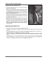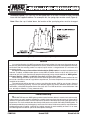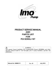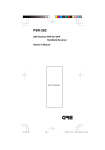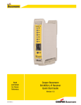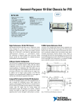
1
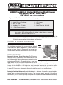
MSD Pro-Billet Digital E-Curve Distributor
Chrysler, 318, 340, 360
PN 8504 -
U.S. Patent 6820602
Important: Read these Instructions before attempting the installation.
Pa r t s I n c l u d e d :
1 - Digital E-Curve Distributor
1 - Rotor, PN 8467
1 - Distributor Cap, PN 8433
1 - Wire Retainer
2 - 1.5" Self Tapping Screws
1 - 3-Pin Harness
1 - O-Ring
1 - Timing Tape Set, PN 8985
WARNING: Before installing the MSD Digital E-Curve Distributor, disconnect the battery cables. When disconnecting the battery cables, always remove the
Negative (-) cable first and install it last.
Note: The terminals of this Digital E-Curve Distributor require spark plug style terminals. You
may need to change the terminals and boots of your wires. MSD offers two kits, PN 8849 or
PN 8848 that are supplied with nine boots and terminals.
DIGITAL E-CURVE FUNCTIONS
RPM LIMIT
This distributor is equipped with an adjustable rev limiter. It
is adjustable from 5,000 - 10,000 rpm by a rotary dial under
the cap and rotor (Figure 1). The rpm will not exceed your
selected amount to protect the engine from overrev damage.
Rev
Limiter
TIMING FUNCTIONS
Electronic Advance Curve Operation: The Electronic
Timing
Advance Curve is managed by a microprocessor built into
Switch 1
Timing Switch 2
the ignition module. You can program an electronic timing
advance curve by adjusting two rotary switches under the
Figure 1 Rotary Dial Adjustments.
distributor cap (Figure 1). A magnetic pickup is used as a
trigger device that tells the ignition module when to fire the
coil. The pickup is triggered by a reluctor mounted to the distributor shaft. This means that you
have to set the distributor at the highest, or Total, amount of advance that you want to achieve
(including vacuum advance) and compensate with one of the selectable ignition curves (shown
on page 4). Following are important definitions that will be used to set up your timing.
Electronic Centrifugal Advance: Since this distributor is all electronic, there really is no mechanical or
centrifugal advance. On a standard distributor, this advance would be called centrifugal so it will be
referred to as the electronic centrifugal advance. The chart on page 4 shows all of the different
combinations you can achieve by simply turning the two rotary dials located under the distributor cap.
MSD IGNITION • 1490 HENRY BRENNAN DR., EL PASO, TEXAS 79936 • (915) 857-5200 • FAX (915) 857-3344
2
INSTALLATION INSTRUCTIONS
Total Timing: This is the total amount of timing that the engine will achieve. This is the amount that
all of the electronic curve and settings will be based from. This setting also includes any amount of
vacuum advance that you plan to use.
Vacuum Advance: The vacuum advance will advance the timing under part throttle conditions
when the engine is not under a heavy load. This advance is added on to the electronic timing curve
as well. The advance will begin as low as 4-in. of vacuum and will max out at 10-in. of vacuum.
There is a separate chart in Figure 3 that illustrates the vacuum curve selection.
Locked-Out Timing: If you do not want to have a timing advance, set the rotary dials in the LockedOut position. This means the timing will not move from the setting you position the distributor in.
You may however, take advantage of a start retard (see below).
Start Retard: When you select Locked-Out timing, the engine may be hard to crank. A start retard
amount can be selected to aid in cranking. This amount can range from 5°, 10°, 15° and 20°. When
the engine is cranking, the timing will be retarded. Once the engine reaches 600 rpm, the timing
will return to the locked-out setting.
Note: The total amount of any timing change that can be achieved is 34° (25° for the electronic
advance with vacuum an additional 9°). This includes the electronic advance as well as the
vacuum advance.
Note: It is recommended to have a dial-back timing light, timing tape or a fully degreed balancer
to set the timing correctly.
CHOOSING AN ADVANCE CURVE
The function of the advance curve is to match the ignition timing to the burning rate of the fuel with
the speed (rpm) of the engine. The piston is traveling much faster through the combustion stroke
at 5,000 rpm compared to 1,000 rpm. Any factor that changes the burning rate of the fuel or the
engine speed can cause a need for an ignition timing change. Figure 2 shows some of the factors
that will affect engine timing.
FACTOR
Cylinder Pressure
Vacuum
Energy of Ignition
Fuel Octane
Mixture (Air/Fuel)
Temperature
Combustion Chamber Shape
Spark Plug Location
Combustion Turbulence
Load
Advance Timing
For
Low
High
Low
High
Rich
Cool
Open
Offset
Low
Light
Retard Timing
For
High
Low
High
Low
Lean
Hot
Compact
Center
High
Heavy
Figure 2 Ignition Timing Factors.
MSD IGNITION • 1490 HENRY BRENNAN DR., EL PASO, TEXAS 79936 • (915) 857-5200 • FAX (915) 857-3344
INSTALLATION INSTRUCTIONS
3
As you can see from the chart, most factors will change throughout the range of the engine operation.
The Digital E-Curve allows you to make timing changes based on these factors.
Example: An engine has 11:1 compression, a high energy ignition and turns 5,500 rpm. With the
specifications given, you will have to retard the timing for the high compression and high energy
ignition. By comparing the engine’s specifications against the chart, a usable timing guideline can
be found. Engines with a combination of items from both columns will require a timing that is set
in the mid range.
Obviously a full technical explanation of correct ignition timing would be very complicated. The
best way to arrive at a suitable ignition curve for your engine is to use the Ignition Timing Factors
Chart as a guide and compare it to the Advance Graphs in Figure 3 until a suitable curve is found.
When selecting your advance curve, use detonation (engine ping) as an indicator of too much
advance, and a decrease in power as an indicator of too little advance. Also consider how the
engine cranks and starts. Too much advance can cause an engine to crank slow or even kick
back. Here are a couple of suggestions.
• Use as much initial advance as possible without encountering excessive starter load.
• Start the electrical advance just above the idle rpm.
• Select an advance curve that produces good acceleration without detonation.
SETTING UP THE DISTRIBUTOR
Once you have determined your desired total timing, you’ll need to select the electronic advance
curve that you want to run (Review the information on page 2 to help choose a curve that matches
your needs). The charts in Figure 3 show all of the different timing curves available. Note that a
letter is given to the curve. Refer to the chart in Figure 4 using this letter to determine the position of
the two rotary dials. If you plan to take advantage of a vacuum advance, select the vacuum curve
number and cross reference it with the mechanical curve’s key letter to get the switch positions.
For example: If you want a 20° curve that advances slowly, select curve E. This means you would
put Rotary Switch 1 in position “0” and Switch 2 in position “5”. If you choose no vacuum advance,
simply do not connect the vacuum port. In this example, if you would prefer 10° of vacuum advance,
choose Vacuum Curve 3 and cross reference it to Timing Curve E. The switch positions would be
Switch 1 “4” and Switch 2 in “5”.
MSD IGNITION • 1490 HENRY BRENNAN DR., EL PASO, TEXAS 79936 • (915) 857-5200 • FAX (915) 857-3344
4
INSTALLATION INSTRUCTIONS
Figure 3 Available Timing Curves.
Figure 4 Advance Curve Switch Position.
MSD IGNITION • 1490 HENRY BRENNAN DR., EL PASO, TEXAS 79936 • (915) 857-5200 • FAX (915) 857-3344
INSTALLATION INSTRUCTIONS
5
INSTALLING THE DISTRIBUTOR
Note: When installing the distributor for the first time, it is recommended to place the switches in
the locked-out timing position. This will assist you in setting the timing curve by ensuring
that the total timing is correct.
1. Remove the existing distributor cap
without disconnecting any of the spark
plug wires.
2. With the cap off, crank the engine until
the rotor is aimed at a fixed point on the
engine or firewall. Note this position by
making a mark (Figure 5).
3. Place the distributor cap back on and note
which plug wire the rotor is pointing to.
MARK THE SPARK PLUG WIRES and
remove the distributor cap.
4. Disconnect the wiring from the distributor.
5. Loosen the distributor hold down clamp
and slide the clamp out of the way.
6. Lift the distributor out of the engine.
7. Install the O-ring to the distributor housing.
Apply a film of clean oil to the O-ring.
8. Install the distributor making sure that the
Figure 5 Marking the Rotor Location.
rotor comes to rest pointing at the fixed
mark. If the distributor will not fully seat
with the rotor pointing to the marked position, you may need to rotate the oil pump shaft until
the rotor lines up and the distributor fully seats.
9. Position and tighten the hold down clamp onto the distributor.
10. Install the distributor cap and spark plug wires one at a time to ensure correct location. A wire
retainer is supplied to secure the wires in place. Align the mounting bosses and use the supplied
1.5" self-tapping Philips screws to hold the the retainer in place.
11.Proceed to wiring the distributor as shown in Figures 6 and 7. Review the starting and tuning
tips information and install the Timing Tape as shown on page 7 before starting the engine.
MSD IGNITION • 1490 HENRY BRENNAN DR., EL PASO, TEXAS 79936 • (915) 857-5200 • FAX (915) 857-3344
6
INSTALLATION INSTRUCTIONS
RED
TO COIL POSTIVE + 12 VOLTS
ORANGE
TO COIL NEGATIVE -
BLACK
TO ENGINE GROUND
GREEN
TO TACH OUTPUT
Figure 6 Wiring the Ready-to-Run Chevrolet Distributor.
NOTE: THE DIGITAL E-CURVE DISTRIBUTORS DO NOT
REQUIRE AN MSD IGNITION, THOUGH THEY CAN
BE USED WITH ONE. THE TIMING CURVE AND
RPM LIMIT WILL STILL FUNCTION.
Figure 7 Connecting an MSD Ignition Control to the Digital E-Curve Distributor.
MSD IGNITION • 1490 HENRY BRENNAN DR., EL PASO, TEXAS 79936 • (915) 857-5200 • FAX (915) 857-3344
INSTALLATION INSTRUCTIONS
7
INSTALLING THE TIMING TAPE
1. Locate the top-dead center or 0° mark on the harmonic
balancer or timing wheel.
2. Select the correct timing tape for your application. Make
sure you know the correct size of the harmonic balancer
or timing wheel you’re using. If this is not known,
measure the diameter of the harmonic balancer or timing
wheel’s edge and note the size.
3. Choose the timing tape that matches your balancer’s
diameter. Be sure that the mating surface is clean of any
dirt, grease or debris. Locate and note the 0° mark on
the timing tape (Figure 8).
4. Align the 0° mark on the tape with the TDC mark on the
balancer. Make sure that the markings on the tape are
facing you, and place the tape on the surface. Use firm
pressure for proper adhesion. ATC (after top-dead
center) will be to the left of the stock mark, and BTC
(before top-dead center) will always be to the right of
the stock mark.
ZERO
DEGREE
(TDC)
Figure 8 The Timing Tape Installed.
STARTING AND TUNING TIPS
• Position the rev limiter rotary dial at your desired rpm limit.
• At this point, the distributor should be installed at your desired timing and wired to the coil, and
ground.
• It is recommended that you have a dial-back timing light or degreed balancer. MSD offers a
timing tape that you can apply to your balancer as PN 8985.
• Select a Locked-Out w/ Start Retard to start the engine (These are Curves Q, R, S or T). This
way you can position the distributor to obtain your ideal total timing before selecting a timing
curve.
• If you are going to use a vacuum advance curve, use a 3/16" vacuum line connected to ported
vacuum. This means a vacuum source that is above the throttle plates. Also, remember to
disconnect and plug the vacuum line when setting the timing curve.
MSD IGNITION • 1490 HENRY BRENNAN DR., EL PASO, TEXAS 79936 • (915) 857-5200 • FAX (915) 857-3344
Installation Option: This Cap can also be bolted down to an MSD Pro-Billet or Billet Distributor
base with the supplied hardware. To accomplish this, the spring clips must be cut off (Figure 9).
Note: When the cap is bolted down, the location of the spark plug wires must be changed.
Figure 9 Optional Installation by Bolting the Cap Down.
Service
In case of malfunction, this MSD component will be repaired free of charge according to the terms of
the warranty. When returning MSD components for service, Proof of Purchase must be supplied for warranty
verification. After the warranty period has expired, repair service is charged based on a minimum and
maximum charge.
All returns must have a Return Material Authorization (RMA) number issued to them before being
returned. To obtain an RMA number please contact MSD Customer Service at (915) 855-7123 or fax a
request to (915) 857-3344. Send the unit prepaid with proof of purchase to the attention of: MSD Ignition,
Customer Service - RMA #, 12120 Esther Lama, Dock 5, El Paso, Texas 79936.
When returning the unit for repair, leave all wires at the length in which you have them installed. Be sure
to include a detailed account of any problems experienced, and what components and accessories are
installed on the vehicle.
The repaired unit will be returned as soon as possible after receipt, COD for any charges. (Ground
shipping is covered by warranty). All units are returned regular UPS unless otherwise noted. For more
information, call the MSD Customer Service Line (915) 855-7123. MSD technicians are available from 7:00
a.m. to 6:00 p.m. Monday - Friday (mountain time).
Limited Warranty
M
SD IGNITION warrants MSD Ignition products to be free from defects in material and workmanship
under normal use and if properly installed for a period of one year from date of purchase. If found to be
defective as mentioned above, it will be replaced or repaired if returned prepaid along with proof of date
of purchase. This shall constitute the sole remedy of the purchaser and the sole liability of MSD Ignition. To
the extent permitted by law, the foregoing is exclusive and in lieu of all other warranties or representations
whether expressed or implied, including any implied warranty of merchantability or fitness. In no event
shall MSD Ignition be liable for special or consequential damages.
MSD IGNITION • 1490 HENRY BRENNAN DR., EL PASO, TEXAS 79936 • (915) 857-5200 • FAX (915) 857-3344
FRM27044
Created 09/05
Printed In U.S.A.