1
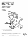
18 in. SCROLL SAW
VARIABLE SPEED
Model No.
315.216090
_
WARMNG:
To reduce the risk of injury,
the user must read and understand the
operator's manual before using this product.
Customer
HeUp Line: 1E800E932E3188
Sears, Roebuck and Co., 3333 Bevedy Rd., Hoffman
Visit the Craftsman web page: www.sears.com/craftsman
983000-769
08-05
Save this manual
Estates, IL 60179 USA
for future
US
reference
[] Warranty ............................................................................................................................................................................
2
[] Introduct(on .......................................................................................................................................................................
2
[] Genera( Safety Rules .....................................................................................................................................................
3=4
[] Specific Safety Rules .........................................................................................................................................................
5
[] Symbols .........................................................................................................................................................................
6=7
[] Eiectr(cal ............................................................................................................................................................................
8
[] Glossary of Terms ..............................................................................................................................................................
9
[] Features .....................................................................................................................................................................
10=11
[] Too(s Needed .................................................................................................................................................................
12
[] Loose Parts ....................................................................................................................................................................
12
[] Assemb(y ...................................................................................................................................................................
13=15
[] Operat(on ...................................................................................................................................................................
15=19
[] Adjustments ....................................................................................................................................................................
20
[] Ma(ntenance ..............................................................................................................................................................
20=21
[] Troub)eshooting ..............................................................................................................................................................
22
[] Notes ..............................................................................................................................................................................
23
[] Exploded V(ew and Parts Ust ....................................................................................................................................
24=27
[] Parts Order(ng/Serv(ce ......................................................................................................................................
ONE YEAR FULL WARRANTY
ON CRAFTSMAN
Back Page
TOOL
(f this Craftsman tool falls due to a defect in material or workmanship within one year from the date of purchase, CON=
TACT TNE NEAREST SEARS PARTS & REPAIR CENTER at I=800=4=MY-NOME ® and Sears w(l( repair it, free of
charge. Th(s warranty app)(es only while th(s product (s (n the United States.
(f th(s tool is used for commerc(al or rental purposes, th(s warranty will apply for only n(nety days from the date of pup
chase.
This warranty gives you spec(fic legal rights, and you may also have other rights wh(ch vary from state to state.
Sears, Roebuck
and Co., Dept. 817WA, Hoffrnan Estates, (L 60179
This too( has many features for making its use more pleasant and enjoyable. Safety, performance, and dependab((ity
have been given top prior(ty in the design of this product making it easy to maintain and operate.
_
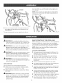
WARMNG:Readandunderstandall instruc=
tions. Failure to follow a(! instruct(ons listed below
may result (n electric shock, fire, and/or serious
personal injury.
READ ALL INSTRUCTIONS
[] KNOW YOUR POWER TOOL. Read the operator's
manual carefu(iy. Learn the app(ications and (imitat(ons
as wel! as the specific potential hazards related to this
tool.
[] GUARD AGA)NST ELECTRICAL SHOCK BY PREVENT(NG BODY CONTACT W(TH GROUNDED
SURFACES. For examp(e: pipes, radiators, ranges,
refrigerator enc(osures.
[] KEEP GUARDS )N PLACE and in good working order.
[] REMOVE ADJUST(NG KEYS AND WRENCHES. Form
the habit of checking to see that keys and adjusting
wrenches are removed from too( before turning it on.
[] KEEP WORK AREA CLEAN. C(uttered areas and
benches inv(te accidents. DO NOT (eave too)s or
p(eces of wood on the too( while it is in operation.
[] DO NOT USE (N DANGEROUS ENV(RONMENTS.
Do not use power tools in damp or wet (ocat(ons or
expose to ra(n. Keep the work area wel( ((t.
[] KEEP CHILDREN AND V(SITORS AWAY. A(( v(s(tors
should wear safety glasses and be kept a safe
distance from work area. Do not (et v(sitors contact
tool or extension cord wh(le operat(ng.
[] MAKE WORKSHOP CH(LDPROOF w(th pad(ocks,
master sw(tches, or by removing starter keys.
[] DON'T FORCE THE TOOL. it wi(! do the job better and
safer at the feed rate for which it was designed.
[] USE THE RIGHT TOOL. Do not force the too! or attachment to do a job for wh(ch it was not designed.
[] USE THE PROPER EXTENS(ON CORD. Make sure
the extens(on cord (s in good condition. Use only a
cord heavy enough to carry the current the product will
draw. An undersized cord wi!l cause a drop in line vo(tage resu(ting in loss of power and overheating. A wire
gauge size (A.W.G.) of at least 16 is recommended for
an extens(on cord 25 feet or less (n length, if in doubt,
use the next heavier gauge. The smal(er the gauge
number, the heav(er the cord.
[] DRESS PROPERLY. Do not wear )oose cloth(ng, neckties, or jewelry that can get caught and draw you into
moving parts. Rubber gloves and nonskid footwear
are recommended when working outdoors. Also wear
protective hair covering to contain long hair.
[] ALWAYS WEAR SAFETY GLASSES W(TH S)DE
SH(ELDS. Everyday eyeg(asses have on(y impactresistant lenses, they are NOT safety glasses.
[] SECURE WORK. Use c(amps or a v(se to hold work
when practica(, (t is safer than using your hand and
frees both hands to operate the tool.
[] DO NOT OVERREACH.
balance at all t(mes.
Keep proper footing and
[] MAINTAIN TOOLS WITH CARE. Keep too(s sharp
and c(ean for better and safer performance. Follow
instructions for lubricating and changing accessories.
[] DISCONNECT TOOLS. When not (n use, before
servicing, or when changing attachments, blades, bits,
cutters, etc., a(! too(s shou(d be disconnected from
power source.
[] AVO)D ACC(DENTAL START(NG. Be sure sw(tch (s off
when plugging in any too!.
[] USE RECOMMENDED ACCESSORIES. Consult the
operator's manual for recommended accessories. The
use of improper accessor(es may result in injury.
[] NEVER STAND ON TOOL. Sedous injury could occur
if the tool is tipped.
[] CHECK DAMAGED PARTS. Before further use of
the tool, a guard or other part that is damaged should
be carefully checked to determine that it wil( operate
properly and perform its intended function. Check for
alignment of mov(ng parts, b(nding of moving parts,
breakage of parts, mounting and any other conditions
that may affect its operation. A guard or other part that
is damaged must be properly repaired or replaced by
an authorized service center to avoid risk of personal
injury.
[] USE THE RIGHT D(RECTION OF FEED. Feed work
into a blade, cutter, or sanding spindle against the
direction or rotation of the Made, cutter, or sanding
sp(ndie only.
[] NEVER LEAVE TOOL RUNNING UNATTENDED.
TURN THE POWER OFF. Don't leave tool unt(( (t
comes to a complete stop.
[] PROTECT YOUR LUNGS. Wear a face or dust mask if
the cutting operation is dusty.
[] PROTECT YOUR HEAR(NG. Wear hearing protect(on
during extended periods of operation.
[] DO NOT ABUSE CORD. Never carry tool by the cord
or yank it to disconnect from receptacle. Keep cord
from heat, oi(, and sharp edges.
[] USE OUTDOOR
is used outdoors,
approved ground
outdoors and so
EXTENSION CORDS. When tool
use only extension cords with
connection that are intended for use
marked.
[] KEEP BLADES CLEAN, SHARP, AND WITH
SUFF(C)ENT SET. Sharp blades min(m(ze sta((ing
and kickback.
[] BLADE COASTS AFTER BE)NG TURNED OFF.
[] NEVERUSEINAN EXPLOSIVE
ATMOSPHERE.
Normalsparkingofthemotorcouldignitefumes.
[] INSPECT
TOOLCORDSPERIODICALLY.
Hfdamaged,
haverepairedby a qualifiedservicetechnicianat
anauthorized
servicefacility.Theconductorwith
insulationhavinganoutersurfacethatisgreenwith
or withoutyellowstripesisthe equipment-groundingconductor.Hfrepairor replacement
of theelectric
cordor plugis necessary,
donotconnecttheequipment-grounding
conductorto a liveterminal.Repair
or replacea damagedor worncordimmediately.
Stay
constantlyawareofcordlocationandkeepit wellaway
fromthe rotatingblade.
[] INSPECT
EXTENSION
CORDSPERIODICALLY
and
replaceif damaged.
[] KEEPTOOLDRY,CLEAN,ANDFREEFROMOIL
ANDGREASE.
Alwaysusea cleanclothwhencleaning.Neverusebrakefluids,gasoline,petroleum-based
products,or anysolventsto cleantoo!.
[] STAYALERTANDEXERCISE
CONTROL.
Watch
whatyouaredoingandusecommonsense.Donot
operatetoo!whenyouaretired.Donotrush.
[] DONOTUSETOOLJFSWITCHDOESNOTTURNJT
ONANDOFF.Havedefectiveswitchesreplacedbyan
authorized
servicecenter.
[] USEONLYCORRECT
BLADES.Usethe rightblade
size,style,andcuttingspeedforthematerialandthe
typeofcut. Bladeteethshouldpointdowntowardthe
table.
[] BEFOREMAKINGA CUT,BESUREALLADJUSTMENTSARESECURE.
[] BESUREBLADEPATHJSFREEOFNAILS.Inspect
forandremoveallnailsfromlumberbeforecutting.
[] NEVERTOUCHBLADEor othermovingpartsduring
use.
[] NEVER START A TOOL WHEN ANY ROTATING COMPONENT JS IN CONTACT WiTH THE WORKPIECE.
[] DO NOT OPERATE A TOOL WHILE UNDER THE
INFLUENCE OF DRUGS, ALCOHOL, OR ANY
MEDICATION.
[] WHEN SERWCING use only identical replacement
parts. Use of any other parts may create a hazard or
cause product damage.
[] USE ONLY RECOMMENDED
ACCESSORIES
listed
in this manual or addendums. Use of accessories
that are not listed may cause the risk of personal
injury. Instructions for safe use of accessories are
included with the accessory.
[] DOUBLE CHECK ALL SETUPS. Make sure blade is
tight and not making contact with saw or workpiece
before connecting to power supply.
[] FIRMLYCLAMPORBOLTthetoolto a workbenchor
tableatapproximately
hipheight.
[] KEEPHANDSAWAYFROMCUTTING
AREA.Donot
reachunderneath
workor in bladecuttingpathwith
yourhandsandfingersforanyreason.Alwaysturnthe
poweroff.
[] ALWAYS
USEA CLAMPto securethe workpiece
whenpossible.
[] ALWAYS
SUPPORT
LONGWORKPIEDES
whilecuttingto minimizeriskof bladepinchingandkickback.
Sawmayslip,walkor slidewhilecuttinglongor heavy
boards.
[] BESURETHEBLADECLEARSTHEWORKPIECE.
Neverstartthesawwiththebladetouchingthe
workpiece.Allowmotorto comeuptofull speed
beforestartingcut.
[] DONOTFEEDTHEMATERIAL
TOOQUICKLY.
Do
notforcetheworkpieceagainstthe blade.
[] NEVERreachbehind,under,or withinthreeinches
of thebladeanditscuttingpathwithyourhandsand
fingersforanyreason.
[] NEVERreachto pickupa workpiece,a pieceof scrap,
or anythingelsethatis inor nearthe cuttingpathofthe
blade.
[] AVOIDAWKWARD
OPERATIONS
ANDHAND
POSiTiONS
wherea suddenslipcouldcauseyour
handto moveintotheblade.ALWAYS
makesureyou
havegoodbalance.NEVERoperatethe sawonthe
flooror in a crouchedposition.
[] IFANYPARTOFTHISSAWIS MISSINGor should
break,bend,or fai!inanyway,orshouldanyelectrical
componentfailto performproperly,shutoffthepower
switch,removethe plugfromthepowersource,and
havedamaged,missing,or failedpartsreplacedbefore
resuming
operation.
[] IFTHEPOWERSUPPLYCORDISDAMAGED,
it
mustbereplacedonlybythemanufacturer
or byan
authorized
servicecenterto avoidrisk.
[] ALWAYS
STAYALERT!Donotallowfamiliarity(gained
fromfrequentuseofthesaw)to causea carelessmistake.ALWAYS
REMEMBER
thata carelessfractionof
a secondis sufficientto inflictsevereinjury.
[] MAKESURETHEWORKAREAHASAMPLELIGHTINGto seetheworkandthatnoobstructionswillinterferewithsafeoperationBEFOREperforming
anywork
usingthesaw.
[] ALWAYS
TURNOFFTHESAWbeforedisconnecting
itto avoidaccidentalstartingwhenreconnecting
to
powersupply.NEVERleavethesawunattended
while
connectedto a powersource.
[] TURNOFFTOOLandwaitforsawbladeto cometo
a completestopbeforemovingworkpieceor changing
settings.
[] SAVETHESEINSTRUCTIONS.
Referto them
frequentlyanduseto instructotherusers.If youloan
someonethistool,loanthemtheseinstructions
also.
WARNING:Somedustcreatedby powersanding,sawing,grinding,drilling,andotherconstruction
activities
containschemicalsknownto causecancer,birthdefectsor otherreproductive
harm.Someexamples
of these
chemicals
are:
leadfromlead-based
paints,
crystalline
silicafrombricksandcementandothermasonryproducts,and
arsenicandchromium
fromchemically-treated
lumber.
Yourriskfromtheseexposuresvaries,dependingonhowoftenyoudothistypeofwork.Toreduceyourexposure
to thesechemicals:
workina wellventilatedarea,andworkwithapprovedsafetyequipment,
suchasthosedust
masksthatarespeciallydesignedto filterout microscopic
particles.
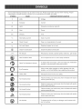
Someofthefollowingsymbolsmaybeusedonthistool.Pleasestudythemandlearntheirmeaning.Proper
interpretation
ofthesesymbolswillallowyouto operatethetoolbetterandsafer.
SYMBOL
NAME
DESJG
NATION/!_XPLANATION
V
Volts
Voltage
A
Amperes
Current
Hz
Hertz
Frequency
(cyclespersecond)
W
Watt
Power
min
Minutes
Time
'%,
Alternating Current
Type of current
m
Direct Current
Type or a characteristic
no
No Load Speed
Rotational speed, at no goad
Class II Construction
Double-insulated
Per Minute
Revolutions, strokes, surface speed, orbits etc., per minute
.../rain
Wet Conditions Alert
_,_
®
of current
construction
Do not expose to rain or use in damp locations.
Read The Operator's Manual
To reduce the risk of injury, user must read and understand
operator's manual before using this product.
Eye Protection
Always wear safety goggles or safety glasses with side
shields, or a full face shield when operating this product.
Safety Alert
Precautions that involve your safety.
No Hands Symbol
Failure to keep your hands away from the blade win result in
serious personal injury.
No Hands Symbol
Failure to keep your hands away from the blade wil! result in
serious personal injury.
No Hands Symbol
Failure to
keep your
hands away from the blade win result in
serious
personal
injury.
No Hands Symbol
Failure to keep your hands away from the blade will result in
serious personal injury.
Hot Surface
To reduce the risk of injury or damage, avoid contact with
any hot surface.
6
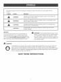
Thefollowingsignalwordsandmeanings
areintendedto explainthelevelsofriskassociated
withthis
product.
SYMBOL SIGNAL
M_=ANJNG
DANGER:
WARNING:
hdicates an imminently hazardous situation, which, if not avoided, wil!
result in death or serious injury.
hdicates a potentially hazardous situation, which, if not avoided, could
result in death or serious injury.
CAUTION:
hdicates a potentially hazardous situation, which, if not avoided, may
result in minor or moderate injury.
CAUTION:
(Without Safety Alert Symbol) hdicates
property damage.
SERVICE
_1_ WARNING:
Servicing requires extreme care and knowledge and
should be performed only by a qualified service technician. For service we suggest you return the product to
your nearest AUTHORIZED SERVICE CENTER for repair.
When servicing, use only identical replacement parts.
_
a situation that may result in
To avoid serious personal injury, do not
attempt to use this product until you read thoroughly
and understand completely the operator's manual.
Save this operator's manual and review frequently for
continuing safe operation and instructing others who
may use this product.
WARNING:
The operation of any power tool can result in foreign objects being thrown into your eyes, which can
result in severe eye damage. Before beginning power tool operation, always wear safety goggles or
safety glasses with side shields and a ful! face shield when needed. We recommend Wide Vision Safety
Mask for use over eyeglasses or standard safety glasses with side shields. Always use eye protection
which is marked to comply with ANSHZ87.1.
SAVE THESE INSTRUCTIONS
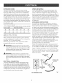
EXTENSION
CORDS
SPEED
Use only 3=wire extension cords that have 3=prong
grounding plugs and 3-pole receptacles that accept the
tool's plug. When using a power tool at a considerable
distance from the power source, use an extension cord
heavy enough to carry the current that the tool will draw.
An undersized extension cord wil! cause a drop in line
voltage, resulting in a loss of power and causing the motor
to overheat. Use the chart provided below to determine
the minimum wire size required in an extension cord. Only
round jacketed cords listed by Underwdter's Laboratories
(UL) should be used.
**Ampere rating
(on tool data p_ate)
0-2.0
2.1-3.4
Cord Length
3.5-5.0
5.1-7.0
7.1-12.0
12.1-16.0
Wire Size (A.W.G.)
25'
16
16
16
16
14
14
50'
16
16
16
14
14
12
100'
16
16
14
12
10
--
**Used on 12 gauge - 20 amp circuit
NOTE: AWG = American Wire Gauge
When working with the tool outdoors, use an extension
cord that is designed for outside use. This is indicated by
the letters "WA" on the cord's jacket.
Before using an extension cord, inspect it for loose or
exposed wires and cut or worn insulation.
_
WARNING:
Keep the extension cord clear of the
working area. Position the cord so that it wil! not get
caught on lumber, tools or other obstructions while
you are working with a power tool. Failure to do so
can result in serious personal injury.
A
WARNING:
AND WRING
The no=load speed of this too! is approximately 1,600
spm. This speed is not constant and decreases under
a load or with lower voltage. For voltage, the wiring in a
shop is as important as the motor's horsepower rating. A
line intended only for lights cannot properly carry a power
tool motor. Wire that is heavy enough for a short distance
win be too light for a greater distance. A line that can
support one power tool may not be able to support two
or three tools.
GROUNDING
INSTRUCTIONS
In the event of a malfunction or breakdown, grounding
provides a path of least resistance for electric current to
reduce the risk of electric shock, This tool is equipped with
an electric cord having an equipment=grounding conduc=
tot and a grounding plug, The plug must be plugged into a
matching outlet that is properly installed and grounded in
accordance with all local codes and ordinances,
Do not modify the plug provided, If it will not fit the outlet,
have the proper outlet installed by a qualified electrician,
Improper connection of the equipment-grounding conductor can result in a risk of electric shock, The conductor
with insulation having an outer surface that is green with or
without yellow stripes is the equipment-grounding
conductor, If repair or replacement of the electric cord or
plug is necessary, do not connect the equipmentgrounding conductor to a live terminal,
Check with a qualified electrician or service personnel if
the grounding instructions are not completely understood,
or if in doubt as to whether the tool is properly grounded,
Repair or replace a damaged or worn cord immediately,
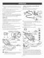
This toot is intended for use on a circuit that has an outlet
like the one shown in figure 1, It also has a grounding pin
like the one shown,
Check extension cords before each
FOOTSWtTCN
PLUG
use. If damaged replace immediately. Never use tool
with a damaged cord since touching the damaged
area could cause electrical shock resulting in serious
injury.
ELECTRICAL
SOROLLSAW
PLUG
CONNECTmON
This tool is powered by a precision built electric motor.
It should be connected to a power supply that is 120
volts, 60 Hz, AC only (normal household current}° Do
not operate this tool on direct current (DC). A substantial
voltage drop will cause a loss of power and the motor wilt
overheat. If the saw does not operate when plugged into
an outlet, double check the power supply.
®
120V GROUNDED OUTLET
Fig. 1
Anti-KickbackPawls(radial
arm and table saws)
A device which, when properly installed and maintained,
is designed to stop the workpiece from being kicked back
toward the front of the saw during a ripping operation.
Arbor
The shaft on which a blade or cutting tool is mounted.
Non-Through Cuts
Any cutting operation where the blade does not extend
completely through the thickness of the workpiece.
Bevel Cut
A cutting operation made with the blade at any angle
other than 90 ° to the table surface.
Push Blocks (for jointer planers}
Device used to feed the workpiece over the jointer planer
cutterhead during any operation. This aid helps keep the
operator's hands well away from the cutterhead.
Chamfer
A cut removing a wedge from a block so the end (or part
of the end) is angled rather than at 90 °.
Compound Cut
A cross cut made with both a miter and a beve! angle.
Cross Cut
A cutting or shaping operation made across the grain or
the width of the workpiece.
Cutterhead (planers and jointer planers}
A rotating cutterhead with adjustable blades or knives.
The blades or knives remove matedal from the workpiece.
Bado Cut
A non-through cut which produces a square-sided notch
or trough in the workpiece (requires a special blade).
Featherboard
A device used to help control the workpiece by guiding it
securely against the table or fence during any ripping
operation.
FPM or SPM
Feet per minute (or strokes per minute), used in reference
to blade movement.
Freehand
Performing a cut without the workpiece
fence, miter gauge, or other aids.
being guided by a
Gum
A sticky, sap-based residue from wood products.
Heel
Alignment of the blade to the fence.
Kerf
The material removed by the blade in a through cut or the
slot produced by the blade in a non-through or partial cut.
Kickback
A hazard that can occur when the blade binds or stalls,
throwing the workpiece back toward operator.
Leading End
The end of the workpiece pushed into the tool first.
Miter Cut
A cutting operation made with the workpiece at any angle
to the blade other than 90 °.
Pilot Hole (drill presses}
A small hole drilled in a workpiece that serves as a guide
for ddlling large holes accurately.
Push Blocks and Push Sticks (for table saws)
Devices used to feed the workpiece through the saw
blade during cutting operations. A push stick (not a push
block) should be used for narrow ripping operations.
These aids help keep the operator's hands well away from
the blade.
Resaw
A cutting operation to reduce the thickness of the workpiece to make thinner pieces.
Resin
A sticky, sap=based substance that has hardened.
Revolutions Per Minute (RPM}
The number of turns completed by a spinning object in
one minute.
Ripping or Rip Cut
A cutting operation along the length of the workpiece.
Riving Knife/Spreader/Splitter
(table saws}
A metal piece, slightly thinner than the blade, which helps
keep the kerf open and also helps to prevent kickback.
Saw Blade Path
The area over, under, behind, or in front of the blade. As
it applies to the workpiece, that area which win be or has
been cut by the blade.
Set
The distance that the tip of the saw blade tooth is bent (or
set) outward from the face of the blade.
Snipe (planers}
Depression made at either end of a workpiece by cutter
blades when the workpiece is not properly supported.
Through Sawing
Any cutting operation where the blade extends completely
through the thickness of the workpiece.
Threw-Back
The throwing back of a workpiece usuaIly caused by the
workpiece being dropped into the blade or being placed
inadvertently in contact with the blade.
Workpiece or Material
The item on which the operation is being done.
Worktable
Surface where the workpiece rests while performing a
cutting, drilling, planing, or sanding operation.
PRODUCTSPECIFICATIONS
Throat....................................................................................................................................................................
18in.
BladeSize......................................................................................................................................................
5 in. plainor pin
NoLoadSpeed.............................................................................................................................................
500- 1,600/rain.
hput ....................................................................................................................................
120V,60Hz,AC©niy, 1.2 Amps
Net Weight .....................................................................................................................................................................
28 bs.
LIGHT 8WITOH
BLADE OLA(V(P_
80NEW8
DRDP FOOT
LOOKKNOB
8AW
TABLE
ONiOFFKNOB W(TH
VARIABLESPEED
BLADE
TENS(ON KNOB
BLADE
TENS(ONLEVER
SAWDUST
EXHAUST
DROP
FOOT
8AW
ARMATURE
AOCE88
/
BLADE
STORAGE DRAWER
SAWDUST
BLOWER/LIGHT
BEVEL $OALE
LOOK KNOB
FOOTBWITON
F(g. 2
10
KNOWYOURSCROLLSAW
_
See Figures 2 - 3.
Before attempting to use this product, familiarize yourself
with all operating features and safety rules.
BEVEL SCALE
The bevel scale and indicator show the degree the saw
table is tilted.
BLADE
CLAMP
SCREWS
WARMNG:
For your own safety, always push
the knob OFF when machine is not in use. Also, in
the event of a power failure, push knob OFF. Lock
the scroll saw switch OFF with a padlock. This wi!!
prevent the machine from starting up again when the
power comes back on. Failure to heed this warning
can result in serious personal injury.
ON/OFF
Blade clamp screws are used when changing saw blades.
KNOB WiTH
VARIABLE
SPEED
Attached under the left side of the table is a blade storage
drawer. Htwill hold up to 20 blades.
Pull the knob out to turn ON the scroll saw and push the
knob in to turn OFF the scroll saw. Turn the knob to adjust
the speed from the high speed of approximately 1,600
SPM (strokes per minute) to the low speed of approxF
mately 500 SPM.
BLADE
SAWDUST
BLADE
STORAGE
TENSION
DRAWER
KNOB
Loosen or tighten blade tension by turning the blade tension knob.
DROP
FOOT AND
DROP FOOT LOCK
/ UGHY
With a convenient ON/OFF switch, the sawdust blower/
light keeps the line of cut on the workpiece clean and
lighted for more accurate scroll cuts. Place the switch in
the ON position, then depress the foot switch to activate
the blower and/or light. For best results, always direct air
flow at the blade and the workpiece.
KNOB
This foot should be lowered until it just rests on top of the
workpiece to prevent the workpiece from lifting, yet not so
much that the workpiece drags. The vertical portion provides a blade guard to prevent accidental blade contact.
SAWDUST
EXHAUST
This feature wil! al!ow you to attach any 1-1/4 in. vacuum
hose for easy sawdust collection.
FOOT SWITCH
Use the foot switch to conveniently turn your scrotl saw
off and on.
LOCK
BLOWER
SAW TABLE WITH
THROAT
PLATE
Your scroll saw has an aluminum saw table with tilt control
POST
for maximum accuracy. The throat plate inserted in the
saw table allows for blade clearance.
To prevent unauthorized use of the scroll saw, we suggest
that you disconnect it from the power supply and install
a padlock (not supplied) through the lock post beside the
knob, as illustrated, to lock the knob in the OFF position.
When the lock is properly installed and locked, the switch
is inoperable. Store the pad!ock key in another !ocation.
SWITCH
A power switch turns the sawdust blower/light
TABLE
LOCK
on and off.
KNOB
Allows you to tilt the table and !ock it at any desired angle
from 5 ° left to 45 ° right.
PADLOCK
Fig. 3
11
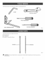
Thefollowingtools(notincluded)areneededfor makingadjustments:
ADJUSTABLE
WRENCH
PHiLLiPSSCREWDRIVER
FLATHEAD 8(?,F{EWDBIVER
Fig. 4
The following items are included with the tool:
[] Plain Blades (3)
[] Pin Blades (2)
[] Operator's
Manual (Not Shown)
PiN BLADE
PLAINBLADE
Fig. 5
WARNING:
The use of attachments or accessories not listed might be hazardous and could cause serious
personal injury.
12
UNPACKING
Thisproducthasbeenshippedcompletelyassembled.
[] Carefully
liftthesawfromthecartonandplaceit ona
levelworksurface.
[] hspectthetoolcarefullyto makesurenobreakage
or
damageoccurredduringshipping.
[] Donotdiscardthepackingmatedaluntilyouhave
carefullyinspectedandsatisfactorily
operatedthetool.
[] Thesawisfactorysetforaccuratecutting.After
assembling
it, checkforaccuracy.Hshipping
f
has
influenced
thesettings,refertospecificprocedures
explainedinthis manual.
[] Hfanypartsaredamagedor missing,pleasecall
1-800-932-3188
forassistance.
A
NOTE: Al! bolts should be inserted from the top. Install
the washers and nuts from the underside of the bench.
The supporting surface where the scrol! saw is mounted
should be examined carefully after mounting to insure
that no movement during use can result. If any tipping or
walking is noted, secure workbench or supporting surface
before beginning cutting operations.
To Reduce Noise and Vibration:
You may wish to place a foam pad or piece of carpet
between the saw base and the workbench to help reduce
noise and vibration.
If a foam pad or piece of carpet is used, do not overtight=
en the mounting bolts. Leave some cushion between the
padding and the saw base to help absorb the noise and
vibration.
WARNING:
Hfany parts are missing, do not operate
this tool until the missing parts are replaced. Failure
to do so could result in possible serious personal
injury.
The size of the padding material should be approximately
24 in. x 12 in. x 1,/2 in.
WARNING:
Do not attempt to modify this tool
or create accessories not recommended for use
If the scroll saw is to be used in a portable application, it is
recommended that you fasten it permanently to a mounting board that can easily be clamped to a workbench or
other supporting surface. The mounting board should be
of sufficient size to avoid tipping of saw while in use. Any
good grade plywood or chipboard with a 3/4 in. thickness
is recommended.
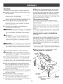
CLAMPING
leading to possible serious personal injury.
WARNING:
Do not connect to a power supply unti!
assembly is complete. Failure to comply could result
in accidental starting and possible serious personal
injury.
SCROLL
SAW TO WORKBENCH
See Figure 6.
with this toot. Any such alteration or modification is
misuse and could result in a hazardous condition
MOUNTING
SCROLL
[] Mount saw to board using holes in saw base as a tern=
plate for hole pattern. Locate and mark the holes where
scrol! saw is to be mounted.
[] Fol!ow last three steps in previous section called
Mounting Scroll Saw to Workbench.
SAW TO WORKBENCH
WARNING:
To avoid serious personal injury from
unexpected tool movement, always securely mount
scroll saw to a workbench.
If the scroll saw is to be used in a permanent application,
we recommend that you secure it in a permanent location such as a workbench. When mounting the saw to a
workbench, holes should be drilled through the supporting
surface of the workbench.
\
[] Each hole in the base of the saw should be bolted
securely using machine bolts, washers, and nuts (not
included). Bolts should be of sufficient length to ac=
commodate the saw base, washers, nuts, and the
thickness of the workbench.
[] Place scroll saw on workbench. Using the saw base as
a pattern, locate and mark the holes where the scroll
saw is to be mounted.
[] Dril! three holes through the workbench.
8AWBABE
[] Place scroll saw on workbench aligning holes in the
saw base with the holes ddIled in the workbench.
C-CLAMP
[] Insert al! three bolts (not included) and tighten securely
with washers and nuts (not included).
MOUNTING
BOARD
WORKBENCH
Fig. 6
13
Hftagboltsarebeingused,makesuretheyarelong
enoughto gothroughholesinthesawbaseandthematerialto whichthesawis beingmounted.
Hfmachineboltsarebeingused,makesuretheyarelong
enoughto gothroughholesinthesawbase,thematerial
thesawis beingmountedto, andthe washersandnuts.
NOTE:Hm
t aybenecessary
to countersink
washersand
nutsonthebottomsideof mountingboard.
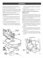
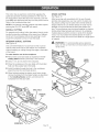
SQUARINGTHESAWTABLETO THE BLADE
should not be relied upon for precision. Make practice
cuts on scrap material to determine if your angle settings are correct.
[] Adjust the drop foot to desired position and securely
retighten the drop foot lock knob.
SETTING
FOR HORJZONYAL
OR
See Figures 8 - 10.
A bevel scale is located under the saw table as a conve-
See Figures 7 - 8.
nient guide for setting the approximate saw table angle for
bevel cutting. When greater precision is required, make
practice cuts on scrap material and adjust the saw table
as necessary for your requirements.
[] Loosen the drop foot lock knob and move drop foot
rod all the way up. Retighten drop foot lock knob.
[] Loosen the table lock knob to tilt the saw table until it
is approximately
the blade.
THE TABLE
BEVEL CUTTING
NOTE: When cutting at angles, the drop foot should be
tilted so it is parallel to the saw table and rests flat against
the workpiece. To tilt the drop foot, !oosen phillips screw,
tilt drop foot to the proper angle, then retighten screw.
perpendicular or at a right angle to
[] Place a small combination square on the saw table
next to the blade to check squareness.
[] Loosen the table lock knob and push down on the right
side of the table, if the table stops at 0 °, the zero degree stop is properly set. if the table stops somewhere
other than zero, adjust the zero degree stop.
[] Loosen the screw holding the scale indicator. Move
indicator to the 0 ° mark and securely tighten screw.
Remember, the bevel scale is a convenient guide but
To adjust:
[] To access the zero degree stop, loosen the table lock
knob, and tilt the table with the right side all the way
down. Just under the front of the saw table is the zero
degree stop.
DROPFOOT
LOCK KNOB
[] Loosen the hex nut and rotate the hex bolt to raise
or lower the bolt as needed to adjust the zero degree
stop. Be sure to check to see that the table is square to
the blade.
DROP
ZERO DEGREESTOP
DROP
FOOTROD
D
BEVEL
SCALE
SCREW
Fig. 8
Fig. 7
14
downoutoftheway,andthetablecanbeangledupto
12°tothe left.
NOTE:Makesurethezerodegreestopis rotatedallthe
waydownor it willcontactthe bladestoragedraweras
youangletothe left.
HE×BOLT
ZERO DEGREE
ASSEMBLY
ZERO
DEGREE
STOP
ASSEMBLY
Fig.9
[] Now,byreturningthetableto thezeroposition,the
zerodegreestopprovidesa quickreference
to the
presetposition.
Thezerostopassemblycanberotatedto theleftand
_
WARNING:
Fig. 1 O
BASIC
Do not allow familiarity with tools to
_
_
WARNING:
SAW
Always wear safety goggles or safety
glasses with side shields when operating tools.
Failure to do so could result in objects being thrown
into your eyes resulting in possible serious injury.
NOTE: After the saw is turned ON, a hesitation before
blade movement is normal.
WARNING:
Do not use any attachments or accessories not recommended by the manufacturer of
this tool. The use of attachments or accessories not
[] During each person's learning period on this saw, it is
expected that some blades will break unti! proper use
and adjustments are learned.
recommended
[] Plan how to hold the workpiece from start to finish.
CUTTING
can result in serious personal injury.
[] Hold the workpiece firmly against the saw table.
[] Use gentle pressure and both hands when feeding the
work into the blade. Do not force the work.
You may use this tool for the following purposes:
[] Guide the workpiece into the blade slowly because the
teeth of the blade are very small and can only remove
material on the down stroke.
[] Cutting wood, wood composition products, plastic,
and other fibrous material up to 2 in. thick
[] Cutting nonferrous metals such as aluminum, brass,
and copper
WARNING:
PROCEDURES
[] Keep your hands away from the blade. Do not hand
hold pieces so small your fingers win go under the
blade guard.
WARNING:
To prevent serious personal injury,
never leave the saw unattended until the blade has
come to a complete stop.
APPLICATIONS
_k
OF THE SCROLL
Before starting a cut, watch the saw run. If you experience
excessive vibration or unusual noise, stop immediately.
Turn the saw off, remove the switch key, and unplug saw.
Do not restart until locating and correcting the problem.
make you careless. Remember that a careless fraction of a second is sufficient to inflict severe injury.
_
OPERATION
[] Avoid awkward operations and hand positions where
a sudden slip could cause serious injury from contact
with the blade. Never place hands in blade path.
Before starting any cutting operation,
[] To get accurate cuts, compensate for blade's tendency
to follow the wood grain as you are cutting wood.
clamp or bolt the saw to a workbench. Never operate the saw on the floor or in a crouched position.
Failure to heed this warning can result in serious
personal injury.
[] Use extra supports (tables, saw horses, blocks, etc.)
when cutting large, small or awkward workpieces.
15
[] Neveruseanotherpersonasa substitutefora table
extensionor asadditionalsupportfora workpiece
that
is longerorwiderthanthebasicsawtable.
[] Whencuttingirregularly
shapedworkpieces,
planyour
worksoit wil!not pinchthe blade.Workpieces
must
nottwist,rockor slipwhilebeingcut.
AVOiDiNGiNJURY
[] Properly support round materials such as dowel rods
or tubing because they have a tendency to ref! during
a cut causing the blade to "bite." To avoid this, always
use a "V" block or clamp workpiece to a miter gauge
[] Make sure saw is level and does not rock. Saw should
always be on a firm, level surface with plenty of room
for handling and properly supporting the workpiece.
When backing out the workpiece, the blade may bind in
the kerf (cut). This is usually caused by sawdust clogging
the kerf or when the blade comes out of the blade holders. If this happens:
[] Before removing loose pieces from the saw table, turn
saw off and wait for all moving parts to stop.
REMOWNG
[] Bolt saw to the support surface to prevent slipping,
walking or sliding during operations like cutting long,
heavy boards.
JAMMED
MATERIAL
[] Wait until saw has come to a full and complete stop.
[] Place the switch in the OFF position.
[] Turn saw off, remove switch key, and unplug cord from
the power source before moving the saw.
[] Unplug the saw from the power source.
[] Do not remove jammed cutoff pieces until blade has
come to a fu!! and complete stop.
[] Remove the saw's blade and the workpiece. See
Removing the Saw Blade.
[] Choose the right size and style blade for the material
and type of cut you plan to do.
[] Wedge the kerf open with a flat screwdriver or wooden
wedge, then remove the blade from the workpiece.
[] Use only recommended
accessories.
WARMNG:
To avoid serious personal injury, turn
saw off and wait for all moving parts to stop before
removing loose pieces from the table.
[] With the exception of the workpiece and related support devises, clear everything off the saw table before
turning the saw on.
Teeth/
ranch
Width
10
7
13
BLADE
Thickness
.! 10 in.
.020 in.
(2.8 mm)
(0.5 mm)
.067 in.
.020 in.
(1.1 ram)
(0.5 ram)
.037 in.
.015 in.
(0.5 ram)
(0.4 ram)
Speed or Strokes
Per Minute
Material
Cut
500-1600
Popular size for cutting hard and soft woods
3/16 in. (4.8 mm) up to 2 in. (51 mm)
Plastics, paper, felt, bone, etc.
750-1250
Extremely thin cuts on materials
3/32 in. (2.4 mm) to 1/2 in. (13 mm) thick
Wood, plastics
500-1000
For tight radius work in thin materials
3/32 in. (2.4 mm) to 1/8 in. (3 mm)
Wood, veneer, bone, fiber, ivory, plastic, etc.
mNFORMATION
[] When choosing a blade, carefully consider the following:
[] Scroll saw blades wear out and must be replaced
frequently for best cutting results. Scroll saw blades
generally stay sharp for 1/2 hour to 2 hours of cutting,
depending on type of material and speed of operation,
• Very fine, narrow blades should be used to scref! cut
in thin material 1/4 in. (6 mm) thick or less.
_ Most blade packages state the size or thickness and
type of material which that blade is intended to cut.
The package should also state the radius or size of
curve that can be cut with that blade size.
Wider blades cannot cut curves as tight or as small
as thinner blades.
[] When cutting wood, best results are achieved when
cutting wood less than one inch thick.
[] When cutting wood thicker than one inch, the user
must guide the workpiece very slowly into the blade
and take extra care not to bend or twist the blade while
[] Blades wear faster when:
Cutting plywood, hardwood, and other laminates.
_ Cutting material thicker than 3/4 in.
Side pressure is applied to the blade.
cutting.
16
CHOICEOF BLADEAND SPEED
Thescrollsawacceptsa widevarietyof bladewidthsand
thicknesses
forcuttingwoodandotherfibrousmaterials.
Htuses5 in.longbladesof eitherthe pinendor plainend
style.Thebladewidthandthicknessandthenumberof
teethperinchto usearedetermined
bythetypeofmaterialandthesizeof theradiusbeingcut.
NOTE:Asa generalrule,alwaysselectnarrowbladesfor
intricatecurvecuttingandwidebladesforstraightand
largecurvecutting.
INSTALLmNG
BLADES
[] Pull up on the tension release.
See Figure 11.
Replacing
Scroll saw blades wear out quickly and must be replaced
frequently for best cutting results. Expect to break some
blades while you learn to use and adjust the saw. Blades
generally stay sharp for 1/2 hour to 2 hours of cutting,
depending on the type of material and speed of operation.
[] Turn off the saw and unplug from power source.
[] Turn blade tension knob clockwise to decrease (or
loosen) blade tension.
[] Pushing up from under the saw table, remove the
throat plate.
[] Loosen both the upper and lower blade clamp screws.
[] Pull up on the blade and push down on the saw arm
to disengage the upper pin in the V-notch of the upper
blade holder. Push the blade downward to disengage
the lower pin in the lower blade holder.
[] Remove the blade.
[] Place the new blade through the opening in the saw
table with the teeth to the front of the saw and pointing
down toward the saw table. The pins on the blade go
under the blade holder in the lower blade holder.
PIN BLADES
Removing
[] Pull up on the blade and press the upper arm down to
position the upper end of the blade in the Vmotch in
the upper blade holder.
the Saw BJade:
[] Turn off the saw and unplug from power source.
_WAF{NING:
the Saw Blade:
[] Securely tighten the upper and lower blade clamp
Failure to turn the saw off and unplug
screws.
the saw from the power source could result in accidental starting causing possible serious injury.
[] Push the tension release back down.
[] Turn the blade tension knob counterclockwise
blade has the desired amount of tension.
unti! the
[] Replace the throat plate.
NOTE: If the blade touches the drop foot on either side
then the drop foot must be adjusted. See Adjusting Drop
Foot in the Adjustments section of this manual.
TENSION
RELEASE
PLAIN BLADES
Removing
[] Turn off the saw and unplug from power source.
V-NOTCN
[] Pull up on the tension release.
[] Turn blade tension knob counterclockwise
BLADE
8AW
BLADE
the Saw Bmade:
to decrease
(or loosen) blade tension.
KNOB
[] Pushing up from under the saw table, remove the
throat plate.
[] Loosen both the upper and !ower blade clamp screws.
[] Remove the blade.
Replacing
the Saw Blade:
[] Turn off the saw and unplug from power source.
[] Place the new blade through the opening in the saw
table with the teeth to the front of the saw and pointing
down toward the saw table.
[] Position blade and tighten the lower blade clamp
screw securely.
Fig. 11
17
[] Pulluponthe bladeandpresstheupperarmdownto
positiontheupperendof thebladeintheupperblade
holder.
[] Securelytightentheupperbladeclampscrew.
[] Pushthetensionreleasebackdown.
[] Turnthebladetensionknobclockwiseunti!theblade
hasthedesiredamountoftension.
[] Replacethethroatplate.
NOTE:ffthe bladetouchesthedropfootoneitherside
thenthedropfootmustbeadjusted.SeeAdjustingDrop
FootintheAdjustments
sectionofthismanual.
DROP FOOT
TURNING
THE SCROLL
SAW ON AND OFF
See Figures 13 o 14.
[] Plug the foot switch into the power source.
[] Plug the scroll saw into the foot switch.
TO pOWEI_
soURCI_
See Figure 12.
To prevent the workpiece from lifting, the drop foot should
be adjusted so it just rests on the top of the workpiece.
The drop foot should not be adjusted so that the
workpiece drags.
[] Pull the ON/OFF knob out to the ON position. The
knob must remain in this position for the foot switch to
supply power to the saw.
Always retighten the drop foot lock knob after each adjustment has been made.
[] Depress foot switch to turn saw ON.
[] Loosen the drop foot lock knob.
NOTE: After saw is turned on, a hesitation before blade
movement is normal.
[] Lower or raise the drop foot to the desired position.
[] Release foot switch to turn saw OFF.
[] Retighten the drop foot lock knob.
SWITCH
PULL/0H
PUSH/0FF
The tall, front part of the drop foot acts as a blade guard
to prevent accidental contact with the blade.
0H
OFF
j
DROP FOOT
LOOK KHOB
DROP
OROP FOOT FOOT ROD
VARIABLE
SPEED
See Figure 14.
,_
The ON/OFF knob also controls the variable speed of
the saw. By turning the knob, the vadable speed control
may be adjusted from the high speed of approximately
! ,600 SPM to the low speed of approximately 500 SPM.
Turn the ON/OFF knob clockwise to increase strokes per
minute and counterc!ockwise to reduce the strokes per
minute.
WARNING: Do not use this foot switch with any tool
other than 21609 Scroll Saw. Failure to follow this
warning may result in serious injury.
18
Thismotorhasanelectroniccontrolthatregulates
the
speedandprovidesoverloadprotectionto themotor.If
themotorfailsto startafterabouttwo seconds,pushthe
knobOFFanddisconnectthesawfromthe powersource.
Referto thetroubleshooting
chart.
NOTE:Ifthe internaloverloadprotectorhasbeentripped,
pushingtheON/OFFknobOFFwil!resetit.
SCROLLCUTTING
Forgeneralscrollcutting,followthepatternlinesby pushingandturningtheworkpieceatthe sametime.Attempt=
ingtoturntheworkpiecewithoutalsopushingit could
causetheworkpieceto bindor twisttheblade.
mNTERIOR
SCROLLCUTTING
STACK
CUTTING
See Figure 16.
After becoming well acquainted with the saw through
practice and experience, you may wish to try stack cut=
ting. Stack cutting may be used when several identical
shapes need to be cut. Several pieces of wood may be
stacked on top and secured to each other before cut=
ting. The wood pieces may be joined together by placing
double=sided tape between each piece or by wrapping
masking tape around the corners or ends of the stacked
wood. You must attach the stacked pieces of wood to
each other so they wil! move on the table as a single piece
of material.
_I1_ WARMNG:
See Figure 15.
To avoid possible serious personal
injury, do not cut more than one loose piece of mate=
rial at a time.
One convenient feature of a scroll saw is that it can be
used to make scroll cuts on the interior of a workpiece
without breaking or cutting through the edge or perimeter
of the board.
To make interior cuts in the workpiece:
[] Remove the scroll saw blade as explained in the In=
stalling Blades section previously in this manual.
[] Dd[[ a 1,/4 in. (6 mm) hole in the workpiece.
[] Place the workpiece on the saw table with the ddlled
hole over the access hole in the table.
[] Install the blade through the hole in the workpiece;
adjust the drop foot and blade tension.
[] When finished making the interior scroll cuts, simply
remove the blade from the blade holders as described
in the Installing Blades section, and remove the
workpiece from the saw table.
TAPE
Fig. 16
Fig. 15
19
WARNING:Beforeperforming
anyadjustment,
makesurethetool isunplugged
fromthe power
supplyandthe switchis inthe OFF(O) position.
Failureto heedthiswarningcouldresultinserious
personalinjury.
ADJUSTINGDROPFOOT
[] Loosenthedropfootlockknob.
[] Centerthe dropfootaroundthesawbladetothe desiredposition.
[] Tightenthedropfootlockknob.
ADJUSTINGBLADETENSION
Fig. 17
See Figure 17.
Adjustments to blade tension can be made at any time.
Check the blade tension by the sound the blade makes
when plucked like a guitar string. This method can be
developed with practice and requires knowing the scroll
Turn the blade tension knob clockwise to decrease (or
loosen) the blade tension.
NOTE: Be careful not to make the blade too loose.
Too little tension may cause the blade to bend or break
before the teeth wear out.
saw.
Pluck the back straight edge of blade while turning blade
tension knob. The sound should be a musical note. The
sound becomes less flat as tension increases, and decreases with too much tension.
Turn the blade tension knob counterclockwise
crease (or tighten) blade tension.
NOTE: Be careful not to adjust the blade too tightly.
Too much tension may cause the blade to break as
soon as you start cutting.
To adjust the blade tension:
[] Turn off and unplug the saw from the power source.
,_
WARNING:
to in-
It has been found that electric tools are subject to
accelerated wear and possible premature failure when
they are used on fiberglass boats, sports cars, wallboard,
spackling compounds, or piaster. The chips and gdndings
from these materials are highly abrasive to electric too!
parts such as bearings, brushes, commutators, etc.
Consequently, it is not recommended that this too! be
used for extended work on any fiberglass material, wallboard, spackling compounds, or piaster. During any use
on these materials it is extremely important that the tool is
cleaned frequently by blowing with an air jet.
When servicing, use only identical
replacement parts. Use of any other part may create
a hazard or cause product damage.
WARNmNG:
Always wear safety goggles or safety
glasses with side shields during power tool operation
or when blowing dust. If operation is dusty, also wear
a dust mask.
GENERAL
Avoid using solvents when cleaning plastic parts. Most
plastics are susceptible to damage from various types of
commercial solvents and may be damaged by their use.
Use clean cloths to remove dirt, carbon dust, etc.
[] Keep the scroll saw clean.
_
[] Do not allow pitch to accumulate on the saw table.
Clean with gum and pitch remover.
WARNING:
[] After cleaning the table top initially, apply a thin coat
of automobile type (paste) wax to the table top so the
wood slides easily while cutting.
Do not at any time let brake fluids,
gasoline, petroleum-based products, penetrating
oils, etc. come in contact with plastic parts. Chemicals can damage, weaken or destroy plastic which
may result in serious personal injury.
2O
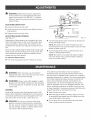
ARM BEARINGS
MOTOR
See Figure 18.
See Figure 19.
Lubricate the arm bearings after the first 10 hours of use.
Oil after every 50 hours of use or whenever there is a
squeak coming from the bearings.
The saw has externally accessible motor brush assemblies that should be checked periodically for wear. When
either one of the two brushes becomes worn, replace
both brushes.
[] Carefully place the saw on its side as shown.
BRUSHES
[] Unplug the saw from the power source.
[] Remove the rubber cap from the upper and the lower
arm of the saw.
[] Carefully place the saw on its side, exposing the underside of the saw housing.
[] Squirt a few drops of SAE20 oi! around the shaft end
and arm bearings. Let oi! soak in overnight, remaining
in this position.
[] Using a flat blade screwdriver, remove the bottom
brush assembly cap through the access hole in the
base and the top brush assembly cap from the top of
the motor.
NOTE: Lubricate the bearings on the other side of the saw
in this same manner.
[] Gently pry the brush assemblies out using a small
screwdriver, point of a nail, or paper clip.
[] If one motor brush is worn down shorter than 1/4 in.,
replace both motor brushes. Do not replace one side
without replacing the other.
NOTE: Ensure curvature of brush matches curvature
of motor, and that motor brush moves freely in brush
tube. Use the blunt end of something thin (eraser end
of pencil, etc.) to push the motor brush into the tube
until it stays.
[] Ensure the motor brush cap is oriented correctly
(straight), then tighten motor brush cap using a hand
powered screwdriver only. Do not overtighten.
o
[V_0TOR_
BRUSH
gFWSH
CAP
Fig. 19
21
PROBLEM
Motor will not run.
Blades breaking.
Vibration (there is always some vibration when the saw is running).
Blade runout (blade not properly
aligned with arm motion).
CAUSE
SOLUTION
Problem with ON/OFF switch, power
cord, foot switch, or outlet
Have worn parts replaced before using scrol! saw again. Have the proper
outlet installed by a qualified electrician.
Motor defective
Do not attempt any repair. Have
repaired by a qualified service technician.
Too much tension
Adjust tension.
Feeding too quickly
Reduce feed rate.
Wrong blade
Use narrow blades for cutting tMn
wood or tight corners and turns; use
wide blades for thicker wood or wide
turns.
Blade twisting in wood
Reduce side pressure on blade; check
blade tension.
Hmproper mounting of saw
Check mounting.
Mounting surface
Check mounting in manual.
Loose table or table resting against
motor
Tighten table lock knob.
Loose motor mounting
Tighten mounting screws.
Blade holders out of line
Realign blade.
22
23
CRAFTSMAN
18 in. (457 ram} SCROLL
SAW - MODEL
NO, 216090
SEE F_GURE B FOR iNSERTiON
POINT INTO PART 38
A
49
47
12
41
14
58
42
/
4O
"
28
_ 30
29
21
41
32
15
18
16
39
FIGURE A
KEY
NO.
1
2
3
4
5
6
7
8
9
10
11
12
13
14
15
16
17
18
19
20
21
22
23
25
26
27
28
29
30
31
32
35
36
PART
NUMBER
180A02030
101069006
180308000
180309000
979809001
101072009
180310000
A37130510060
979730001
Al1003050083
180312000
979804001
180313000
180303000
180102000
180105000
E07050613002
A10003060103
A18003050109
980123001
979786001
979785001
979784001
A10003050150
979772001
979820001
979821001
979822001
A38030612019
979824001
979825001
180111000
180113000
DESCRIPTION
QTY.
Upper Clamp Assembly .................................
Saw Blade ......................................................
Throat Plate ....................................................
Table ...............................................................
Table Screw ....................................................
Saw Blade ......................................................
Blade Drawer .................................................
* Washer (M5) ...................................................
* Screw (M5 x 8) ...............................................
* Screw (M5 x 8) ...............................................
Lock Handle ...................................................
1
3
1
1
1
2
1
3
3
2
1
* Washer (M6) ...................................................
Scale ..............................................................
Scale Bracket .................................................
Motor Cover ...................................................
Power Cord Assembly ...................................
Stain Relief .....................................................
2
1
1
1
1
1
* Screw (M6 x 10) .............................................
Clamp Screw ..................................................
Motor Assembly .............................................
Brush Holder ..................................................
Brush Assembly .............................................
Brush Cap ......................................................
* Screw (M5 x 15) .............................................
indicator .........................................................
4
2
1
2
2
2
3
1
* Hex Bolt (M5 x 15) ..........................................
* Hex Nut (M5) ..................................................
Hex Bolt (Socket Hd. Special) ........................
* Washer (M6) ...................................................
Stopper ..........................................................
Spring Pin (M5 x 10 mm) ................................
Rubber Feet ...................................................
Base ...............................................................
1
1
1
1
1
1
4
1
* STANDARD HARDWARE
KEY
NO.
PART
NUMBER
37
38
39
40
41
42
43
44
45
46
47
48
49
50
52
53
54
55
56
57
58
59
60
61
62
63
64
65
66
67
68
69
70
E07000846157
A10003050105
979769001
180257000
A03003050168
979766001
979767001
979775001
979762001
979758001
180237100
A36030508123
180238000
180242000
979776001
979759001
180250000
180241000
A63000000051
A10003040180
180106000
180110000
A30003004005
904222009
180108000
8180a00!10
180112000
180101000
180109000
8180A21000
180107000
180311000
180607000
iTEM -- MAY BE PURCHASED
DESCRiPTiON
QTY.
Clamp (UC-15) ...............................................
* Screw (M5 x 10 Pan Hd.) ...............................
* Hex Bolt (M6 x 20) ..........................................
Data Plate .......................................................
* Hex Bolt (M5 x 16) ..........................................
* Screw (M4 x 30) .............................................
Nozzle ............................................................
Left Counterbalance .......................................
Link .................................................................
3
3
4
1
3
2
1
1
1
Bail Bearing (625ZZ) .......................................
Right Counterbalance ....................................
* Washer (M5) ...................................................
Screw .............................................................
2
1
1
1
Spacer ............................................................
Set Screw (M6 x 6 mm) ..................................
* Screw (M4 x 8) ...............................................
* Fixed Plate .....................................................
1
2
1
1
Spacer ............................................................
* O-ring (P-5) ....................................................
* Screw (M4 x 18 mm) ......................................
Table Spindle ..................................................
Table Pivot Stand ...........................................
* Hex Nut (M4) ..................................................
Label ..............................................................
1
1
2
1
1
2
1
Large Sponge .................................................
2
Pc Board ........................................................
1
Inslulation Film ...............................................
1
Lead Wire .......................................................
1
Small Sponge .................................................
1
Transformer Board Assembly ......................... 1
Medium Sponge .............................................
1
BIade Drawn Bracket ..................................... 1
Foot Switch ....................................................
1
LOCALLY
CRAFTSMAN
46
18 in. {457 mm} SCROLL
SAW - MODEL
NO. 216090
47
-_
18
5O
49
16
48
17
19
45
2O
29
34
49
44
35
28
37
i
26
L
14
38
\%
35 j
_36
Ir
SEE FIGURE A
FNGURE B
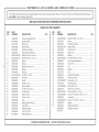
CRAFTSMAN 18 in, (457 rnrn) SCROLL SAW - MODEL NO. 216090
The modeI number will be found on a plate attached to the motor housing. Always mention the model number in all correspondence
Scroll Saw or when ordering repair parts.
SEE BACK PAGE FOR PARTS ORDERING
regarding your
1
iNSTRUCTiONS
PARTS UST FOR FmGURE B
KEY
NO,
1
2
3
4
5
6
7
8
9
10
!1
12
13
14
15
16
17
18
19
20
21
22
23
24
25
26
27
28
PART
NUMBER
102032002
979745001
979747001
180243000
979749001
180a040!0
A42001030109
A4200!030140
180232000
108217000
180253000
180210000
180204000
A4100!050!50
8000200011
180226000
180259000
180258000
180260000
180255000
166102100
180219000
180229000
180a02060
180261000
979829001
180256000
979765001
DESCRIPTION
QTY.
Tension Adjusting Knob .............................
Support Plate .............................................
Drop Foot ...................................................
Washer (M5) ...............................................
Hold Down Clamp ......................................
Support Bar Assembly ...............................
Spring Pin (M3 x 10 mm) ...........................
Spring Pin (M3 x 14 mm) ...........................
Bellow ........................................................
Blower ........................................................
Blade Tension Lever ...................................
Washer .......................................................
Bracket .......................................................
1
1
1
1
1
1
1
1
1
1
1
1
1
Pin (M5 x 15 mm) .......................................
Vr Switch ....................................................
Switch ........................................................
Switch Label ..............................................
2
1
1
1
Warning Label ............................................
On/Off Knob Label .....................................
On/Off Knob ...............................................
Motor Pointer .............................................
Switch Cover ..............................................
Led .............................................................
1
1
1
1
1
1
Sawdust Blower/Light ................................
Logo Plate ..................................................
Rubber Stopper .........................................
Left Arm Cover ...........................................
1
2
4
1
Bearing Bushing .........................................
4
KEY
NO,
PART
NUMBER
29
30
31
32
33
34
35
36
37
38
39
40
41
42
43
44
45
46
47
48
49
50
51
52
53
A41001052340
180215000
180205000
A35030616160
180254000
180201000
180223000
A42001050220
180a02040
180212000
180240000
180248000
180211000
180a02070
180252000
Al1003040255
180114000
Al1003040350
180251000
A95001050120
Al1003040400
180262000
A10003040107
180244000
180245000
983000769
04-!2-05
* STANDARD HARDWARE iTEM -- MAY BE PURCHASED
DESCRIPTION
QTY.
Spring Pin (M5 x 23.4 mm) ........................
Spring .........................................................
Adjustment Screw ......................................
* Washer (M6) ...............................................
Tension Knob .............................................
1
1
1
1
1
Upper Arm ..................................................
Bearing .......................................................
Spring Pin (M5 x 22 mm) ...........................
Lower Clamp Assembly .............................
Lower Arm ..................................................
Pin ..............................................................
Washer .......................................................
Link ............................................................
1
2
2
1
1
1
4
1
Lead Wire Assembly ..................................
Right Arm Cover ........................................
* Screw (M4 x 25) .........................................
Warning Label ............................................
* Screw (M4 x 35) .........................................
Drop Foot Lock Knob ................................
Set Screw (M5 x 12 mm) ............................
Screw, Ph. Hd. (M4 x 40 mm + S) ..............
Led Label ...................................................
1
1
3
1
3
1
1
4
1
Screw, Ph. Hd. (M4 x 10 mm) .................... 4
Spacer ........................................................
1
Retaining Ring (K7) .................................... 1
Operator's Manual
LOCALLY
Your Home
For repair-in
your home-of all major brand appliances,
lawn and garden equipment, or heating and cooling systems,
no matter who made it, no matter who sold it!
iiiiiiiiiiiiiiiiii
iiiiiiiiiiiiiiiiii
For the replacement parts, accessories and
owner's manuals that you need to do-it-yourself.
iiiiiiiiiiiiiiiiH
HHHHHHHHH
For Sears professional installation of home appliances
and items like garage door openers and water heaters.
HHHHHHHHH
HHHHHHHHH
HHHHHHHHH
1-800-4-MY-HOME
Call anytime,
®
(1-800-469-4663)
day or night (U. S.A. and Can ad a)
HHHHHHHHH
HHHHHHHHH
www.sears.com www.sears.c_
OurHome
HHHHHHHHH
For repair of carry-in items like vacuums, lawn equipment,
and electronics, call or go on-line for the location of your nearest
Sears Parts & Repair Center.
iiiiiiiiiiiiiiiii
1-8oo-488-1222
ca,,
anytime,nioht on, )
w_.sears.com
To purchase a protection agreement (U.S.A.)
or maintenance agreement (Canada)on
a product serviced
1-800-827-6655
Para pedir servicio
a domicilio,
(U.S.A.)
de reparacien
y pard ordenar
1-800-361-6665
Au Canada
(1-888-784-6427)
Trademark
/
TM
Trademark
(Canada'
pour service en fran(_aB:
1-800-LE-FOYER Mc
(1-800-533-6937)
piezas:
1-888-S U-HOGAR SM
® Registered
by Sears:
www.sears.ca
/
SM
Service
Mark of Sears, Roebuck
® Marca Registrada / TM Marca de F&brica / SMMarca de Servicio de Sears,
MC Marque de commerce / MDMarque deposed de Sears, Roebuck and Co.
and Co.
Roebuck
and Co.
® Sears,
Roebuck
and Co.
.................