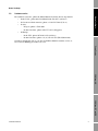
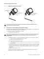
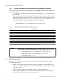
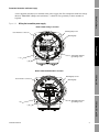
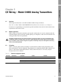
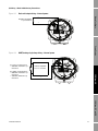
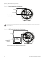
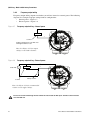
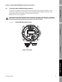
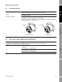
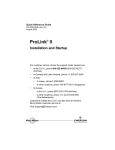
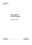
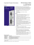
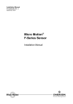
1
Installation Manual
P/N 20003402, Rev. D
April 2008
Micro Motion®
Model 2400S Transmitters
Installation Manual
©2008, Micro Motion, Inc. All rights reserved. ELITE and ProLink are registered trademarks, and MVD and MVD Direct Connect
are trademarks of Micro Motion, Inc., Boulder, Colorado. Micro Motion is a registered trade name of Micro Motion, Inc., Boulder,
Colorado. The Micro Motion and Emerson logos are trademarks and service marks of Emerson Electric Co. All other trademarks
are property of their respective owners.
Contents
Chapter 1
Before You Begin . . . . . . . . . . . . . . . . . . . . . . . . . . . . . . . . . . . . . 1
1.1
1.2
1.3
1.4
1.5
1.6
Chapter 2
2.6
5
5
5
6
7
8
8
Overview . . . . . . . . . . . . . . . . . . . . . . . . . . . . . . . . . . . . . . . . . . . . . . . . . . . . . . . . . .
Moisture protection . . . . . . . . . . . . . . . . . . . . . . . . . . . . . . . . . . . . . . . . . . . . . . . . . .
I/O options. . . . . . . . . . . . . . . . . . . . . . . . . . . . . . . . . . . . . . . . . . . . . . . . . . . . . . . . .
Wiring the outputs . . . . . . . . . . . . . . . . . . . . . . . . . . . . . . . . . . . . . . . . . . . . . . . . . . .
3.4.1
mA output wiring . . . . . . . . . . . . . . . . . . . . . . . . . . . . . . . . . . . . . . . . . . .
3.4.2
Frequency output wiring. . . . . . . . . . . . . . . . . . . . . . . . . . . . . . . . . . . . . .
3.4.3
Discrete output wiring . . . . . . . . . . . . . . . . . . . . . . . . . . . . . . . . . . . . . . .
3.4.4
Discrete input wiring . . . . . . . . . . . . . . . . . . . . . . . . . . . . . . . . . . . . . . . .
11
11
11
12
12
16
17
19
I/O Wiring – Model 2400S PROFIBUS-DP and DeviceNet Transmitters 21
4.1
4.2
4.3
4.4
Installation Manual
Overview . . . . . . . . . . . . . . . . . . . . . . . . . . . . . . . . . . . . . . . . . . . . . . . . . . . . . . . . . . .
Moisture protection . . . . . . . . . . . . . . . . . . . . . . . . . . . . . . . . . . . . . . . . . . . . . . . . . . .
Rotating the transmitter on the sensor (optional) . . . . . . . . . . . . . . . . . . . . . . . . . . . .
Rotating the user interface module on the transmitter (optional) . . . . . . . . . . . . . . . .
Power supply requirements . . . . . . . . . . . . . . . . . . . . . . . . . . . . . . . . . . . . . . . . . . . . .
2.5.1
DC power requirements for Model 2400S Analog and
PROFIBUS-DP transmitters. . . . . . . . . . . . . . . . . . . . . . . . . . . . . . . . . . . .
Wiring the power supply . . . . . . . . . . . . . . . . . . . . . . . . . . . . . . . . . . . . . . . . . . . . . . .
I/O Wiring – Model 2400S Analog Transmitters. . . . . . . . . . . . . . . . 11
3.1
3.2
3.3
3.4
Chapter 4
1
1
1
2
2
3
Transmitter Orientation and Power Supply . . . . . . . . . . . . . . . . . . . . 5
2.1
2.2
2.3
2.4
2.5
Chapter 3
Overview . . . . . . . . . . . . . . . . . . . . . . . . . . . . . . . . . . . . . . . . . . . . . . . . . . . . . . . . . . .
Safety . . . . . . . . . . . . . . . . . . . . . . . . . . . . . . . . . . . . . . . . . . . . . . . . . . . . . . . . . . . . .
Flowmeter components . . . . . . . . . . . . . . . . . . . . . . . . . . . . . . . . . . . . . . . . . . . . . . . .
Transmitter installation overview . . . . . . . . . . . . . . . . . . . . . . . . . . . . . . . . . . . . . . . . .
Flowmeter documentation . . . . . . . . . . . . . . . . . . . . . . . . . . . . . . . . . . . . . . . . . . . . . .
Customer service . . . . . . . . . . . . . . . . . . . . . . . . . . . . . . . . . . . . . . . . . . . . . . . . . . . .
Overview . . . . . . . . . . . . . . . . . . . . . . . . . . . . . . . . . . . . . . . . . . . . . . . . . . . . . . . . . .
Moisture protection . . . . . . . . . . . . . . . . . . . . . . . . . . . . . . . . . . . . . . . . . . . . . . . . . .
I/O wiring for Model 2400S PROFIBUS-DP transmitters . . . . . . . . . . . . . . . . . . . . .
4.3.1
Enabling internal termination . . . . . . . . . . . . . . . . . . . . . . . . . . . . . . . . . .
I/O wiring for Model 2400S DeviceNet transmitters . . . . . . . . . . . . . . . . . . . . . . . . .
21
21
21
22
23
iii
Contents
Appendix A Dimensions and Specifications . . . . . . . . . . . . . . . . . . . . . . . . . . 25
A.1
A.2
A.3
A.4
A.5
A.6
A.7
A.8
A.9
A.10
A.11
Dimensions . . . . . . . . . . . . . . . . . . . . . . . . . . . . . . . . . . . . . . . . . . . . . . . . . . . . . . . .
Physical specifications . . . . . . . . . . . . . . . . . . . . . . . . . . . . . . . . . . . . . . . . . . . . . . .
Power supply – Models 2400S Analog and PROFIBUS-DP . . . . . . . . . . . . . . . . . . .
Electrical connections . . . . . . . . . . . . . . . . . . . . . . . . . . . . . . . . . . . . . . . . . . . . . . . .
User interface . . . . . . . . . . . . . . . . . . . . . . . . . . . . . . . . . . . . . . . . . . . . . . . . . . . . . .
Input/output signals. . . . . . . . . . . . . . . . . . . . . . . . . . . . . . . . . . . . . . . . . . . . . . . . . .
Digital communications . . . . . . . . . . . . . . . . . . . . . . . . . . . . . . . . . . . . . . . . . . . . . . .
Host interface . . . . . . . . . . . . . . . . . . . . . . . . . . . . . . . . . . . . . . . . . . . . . . . . . . . . . .
Environmental limits . . . . . . . . . . . . . . . . . . . . . . . . . . . . . . . . . . . . . . . . . . . . . . . . .
Environmental effects . . . . . . . . . . . . . . . . . . . . . . . . . . . . . . . . . . . . . . . . . . . . . . . .
Hazardous area classifications . . . . . . . . . . . . . . . . . . . . . . . . . . . . . . . . . . . . . . . . .
25
27
27
28
29
31
32
32
33
33
33
Appendix B Return Policy. . . . . . . . . . . . . . . . . . . . . . . . . . . . . . . . . . . . . . . 35
B.1
B.2
New and unused equipment . . . . . . . . . . . . . . . . . . . . . . . . . . . . . . . . . . . . . . . . . . . 35
Used equipment . . . . . . . . . . . . . . . . . . . . . . . . . . . . . . . . . . . . . . . . . . . . . . . . . . . . 35
Index . . . . . . . . . . . . . . . . . . . . . . . . . . . . . . . . . . . . . . . . . . . . . . . . . . . . . 37
iv
Micro Motion® Model 2400S Transmitters
1.1
Before You Begin
Chapter 1
Before You Begin
Overview
This chapter provides an orientation to the use of this manual. This manual describes the procedures
required to install the following transmitters:
Model 2400S transmitter with analog outputs
•
Model 2400S transmitter with PROFIBUS-DP
•
Model 2400S transmitter with DeviceNet™
Power Supply
1.2
•
Safety
Safety messages are provided throughout this manual to protect personnel and equipment. Read each
safety message carefully before proceeding to the next step.
Improper installation in a hazardous area can cause an explosion. When installing in a hazardous area,
refer to Micro Motion approvals instructions, shipped with the product or available from the Micro
Motion web site.
Hazardous voltage can cause severe injury or death. Make sure power is shut off before installing the
transmitter.
I/O Wiring – AN
Follow all instructions. Improper installation could cause measurement error or flowmeter failure.
1.3
Flowmeter components
The Model 2400S transmitter is mounted on a Micro Motion sensor. The transmitter and sensor
together comprise the Micro Motion flowmeter.
Figure 1-1 provides a view of the Model 2400S transmitter mounted on a sensor.
I/O Wiring – DP and DN
Installation Manual
1
Before You Begin
Figure 1-1
Model 2400S transmitter
Transmitter housing cover
Conduit openings
Clamping ring
Sensor case
1.4
Transmitter installation overview
The Model 2400S transmitter component is mounted integrally with the sensor and grounded via the
sensor. To install and ground the sensor, see the sensor documentation.
Additional transmitter installation steps are documented in this manual:
1.5
•
Rotate the transmitter on the sensor (optional) – see Chapter 2
•
Rotate the user interface module on the transmitter (optional) – see Chapter 2
•
Wire and ground the transmitter’s power supply – see Chapter 2
•
Wire the transmitter I/O:
-
For the Model 2400S Analog transmitter, see Chapter 3
-
For the Model 2400S PROFIBUS-DP and DeviceNet transmitters, see Chapter 4
Flowmeter documentation
Table 1-1 lists documentation sources for other required information.
Table 1-1
2
Flowmeter documentation resources
Topic
Document
Sensor installation
Sensor documentation shipped with sensor
Hazardous area installation
See the approval documentation shipped with the
transmitter, or download the appropriate
documentation from the Micro Motion web site
(www.micromotion.com)
Transmitter configuration,
flowmeter startup and use, and
flowmeter troubleshooting
• Micro Motion® Model 2400S Transmitters with
Analog Outputs: Configuration and Use Manual
• Micro Motion® Model 2400S Transmitters with
PROFIBUS-DP: Configuration and Use Manual
• Micro Motion® Model 2400S Transmitters with
DeviceNet™: Configuration and Use Manual
Micro Motion® Model 2400S Transmitters
Before You Begin
1.6
Customer service
•
In the U.S.A., phone 800-522-MASS (800-522-6277) (toll free)
•
In Canada and Latin America, phone +1 303-527-5200 (U.S.A.)
•
In Asia:
•
-
In Japan, phone 3 5769-6803
-
In other locations, phone +65 6777-8211 (Singapore)
Before You Begin
For technical assistance, phone the Micro Motion Customer Service department:
In Europe:
-
In the U.K., phone 0870 240 1978 (toll-free)
-
In other locations, phone +31 (0) 318 495 555 (The Netherlands)
Customers outside the U.S.A. can also email Micro Motion customer service at
[email protected].
Power Supply
I/O Wiring – AN
I/O Wiring – DP and DN
Installation Manual
3
4
Micro Motion® Model 2400S Transmitters
2.1
Before You Begin
Chapter 2
Transmitter Orientation and Power Supply
Overview
This chapter describes:
Rotating the transmitter on the sensor (optional)
•
Rotating the user interface module on the transmitter (optional)
•
Power supply requirements and wiring
Power Supply
2.2
•
Moisture protection
When rotating or wiring the transmitter, guard against condensation or excessive moisture inside the
transmitter housing. Be sure that the conduit openings are completely sealed after all installation and
wiring procedures have been performed.
Improperly sealed housings can expose electronics to moisture, which can cause measurement error
or flowmeter failure. Install the meter so that the conduit openings do not point upward, and install drip
legs in conduit or cable. Inspect and grease all gaskets and O-rings. Fully close and tighten all housing
covers and conduit openings.
2.3
Rotating the transmitter on the sensor (optional)
I/O Wiring – AN
For easier access to the user interface or the wiring terminals, the transmitter can be rotated on the
sensor in 45° increments, for eight different orientations.
To rotate the transmitter on the sensor:
1. Referring to Figure 2-1, unscrew the clamp that holds the transmitter to the feedthrough.
2. Gently lift the transmitter on the feedthrough until it disengages from the notches on the
feedthrough. You will not be able to remove the transmitter completely.
3. Rotate the transmitter to the desired position.
4. Lower the transmitter, sliding it onto the notches on the feedthrough.
5. Replace the clamp and tighten the screw.
I/O Wiring – DP and DN
Installation Manual
5
Transmitter Orientation and Power Supply
Figure 2-1
Rotating the transmitter on the sensor
Clamping ring
Feedthrough
Feedthrough
notches
Do not rotate the housing more than 360°. Excessive rotation can damage the wiring and cause
measurement error or flowmeter failure.
2.4
Rotating the user interface module on the transmitter (optional)
For easier access, the user interface module (whether or not the transmitter has an LCD display) can
be rotated on the transmitter up to 360° in 90° increments.
To rotate the user interface module on the transmitter:
1. Remove power from the unit.
Removing the transmitter housing cover in a hazardous area while the transmitter is powered up can
cause an explosion. Shut off power to the transmitter before removing the housing cover in a
hazardous area.
2. Referring to Figure 2-2, remove the transmitter housing cover and user interface module:
a. Loosen the four transmitter housing cover screws.
b. Remove the transmitter housing cover.
c. Loosen the two user interface screws.
d. Gently lift the user interface module, disengaging it from the user interface connector on
the transmitter.
3. On the back of the user interface module, four user interface connectors are provided. Rotate
the user interface module to the desired position and plug it into the user interface connector
on the transmitter. (See Figure 2-3 for another view of the user interface connector on the
transmitter.)
4. Tighten the user interface screws.
5. Replace the transmitter housing cover and tighten the transmitter housing cover screws.
6. Restore power to the transmitter if required.
6
Micro Motion® Model 2400S Transmitters
Transmitter Orientation and Power Supply
Figure 2-2
Rotating the user interface module on the transmitter
Before You Begin
4 × Transmitter
housing cover screws
(captive)
User interface module
Transmitter housing
cover
2 × User interface
screws (captive)
2.5
Power Supply
*
Transmitter with aluminum housing shown.
Procedure for stainless steel housing is similar.
Power supply requirements
Model 2400S Analog and Model 2400S PROFIBUS-DP transmitters can accept either AC or DC
power. The transmitter automatically recognizes the source voltage. Power supply requirements are:
•
-
85–265 VAC
-
50/60 Hz
-
4 watts typical, 7 watts maximum
I/O Wiring – AN
•
AC power:
DC power:
-
18–100 VDC
-
4 watts typical, 7 watts maximum
The Model 2400S DeviceNet transmitter is powered from the DeviceNet network per the DeviceNet
specification. There is no need to connect separate power-supply wiring for the Model 2400S
DeviceNet transmitter. Skip to Chapter 4.
I/O Wiring – DP and DN
Installation Manual
7
Transmitter Orientation and Power Supply
2.5.1
DC power requirements for Model 2400S Analog and PROFIBUS-DP transmitters
If you are using DC power with a Model 2400S Analog or PROFIBUS-DP transmitter, the following
requirements apply:
•
At startup, the transmitter power source must provide a minimum of 1 A of short-term current
per transmitter.
•
Length and conductor diameter of the power cable must be sized to provide 18 VDC minimum
at the power terminals, at a load current of 0.5 A. (This assumes a single transmitter per cable.
Connecting multiple transmitters to a single cable should generally be avoided.) To size the
cable, refer to Table 2-1 and use the following formula as a guideline:
MinimumSupplyVoltage = 18V + ( CableResistance × CableLength × 0.5A )
Table 2-1
Typical power cable resistances at 68 °F (20 °C)
Gauge
Resistance(1)
14 AWG
0.0050 Ω/foot
16 AWG
0.0080 Ω/foot
18 AWG
0.0128 Ω/foot
20 AWG
0.0204 Ω/foot
2
0,0136 Ω/meter
2
0,0228 Ω/meter
2,5 mm
1,5 mm
0,0340 Ω/meter
1 mm2
0,75 mm
0,0460 Ω/meter
2
0,0680 Ω/meter
2
0,5 mm
(1) These values include the resistance of both high and low conductors in a cable.
Example
The transmitter is mounted 350 feet from a DC power supply. If you want to use
16 AWG cable, calculate the required voltage at the DC power supply as follows:
MinimumSupplyVoltage = 18V + ( CableResistance × CableLength × 0.5A )
MinimumSupplyVoltage = 18V + ( 0.0080 Ohms/ft × 350 ft × 0.5A )
MinimumSupplyVoltage = 19.4V
2.6
Wiring the power supply
Note: This procedure is required only for Model 2400S Analog and PROFIBUS-DP transmitters.
To wire the power supply:
1. Remove the transmitter housing cover and user interface module as described in Section 2.4.
2. Unscrew the warning flap screw and raise the warning flap. Figure 2-3 shows the warning flap
in the open position.
3. Connect the power supply wires to terminals 9 and 10, as shown in Figure 2-3.
4. Ground the power supply to the transmitter’s internal grounding screw, shown in Figure 2-3.
5. Lower the warning flap and tighten the warning flap screw.
8
Micro Motion® Model 2400S Transmitters
Transmitter Orientation and Power Supply
Figure 2-3
Before You Begin
A user-supplied switch may be installed in the power supply line. For compliance with low-voltage
directive 2006/95/EC (European installations), a switch in close proximity to the transmitter is
required.
Wiring the transmitter power supply
Model 2400S Analog transmitter
Warning flap screw
User interface connector
Warning flap
Power Supply
Transmitter internal
grounding screw
+ (L)
– (N)
Model 2400S PROFIBUS-DP transmitter
I/O Wiring – AN
Warning flap screw
User interface connector
Warning flap
I/O Wiring – DP and DN
Transmitter internal
grounding screw
+ (L)
– (N)
Installation Manual
9
10
Micro Motion® Model 2400S Transmitters
3.1
Before You Begin
Chapter 3
I/O Wiring – Model 2400S Analog Transmitters
Overview
This chapter describes how to wire I/O for Model 2400S Analog transmitters.
Note: To wire I/O for Model 2400S PROFIBUS-DP and DeviceNet transmitters, see Chapter 4.
It is the user’s responsibility to verify that the specific installation meets the local and national safety
requirements and electrical codes.
Moisture protection
When rotating or wiring the transmitter, guard against condensation or excessive moisture inside the
transmitter housing. Be sure that the conduit openings are completely sealed after all installation and
wiring procedures have been performed.
Power Supply
3.2
Improperly sealed housings can expose electronics to moisture, which can cause measurement error
or flowmeter failure. Install the meter so that the conduit openings do not point upward, and install drip
legs in conduit or cable. Inspect and grease all gaskets and O-rings. Fully close and tighten all housing
covers and conduit openings.
3.3
I/O options
Table 3-1
Channel
A
B
I/O Wiring – AN
Table 3-1 lists the options for the transmitter’s two I/O channels. Before wiring Channel B, ensure
that you know how it will be configured. For information on configuring Channel B for function and
power, see the manual entitled Micro Motion® Model 2400S Transmitters with Analog Outputs:
Configuration and Use Manual.
Terminal configuration options
Terminals
1&2
3&4
Function
Power
Comm
Internal
(1)
or external
HART/Bell 202
Frequency
Internal
(1)
or external
None
Discrete output
Internal or external
None
Discrete input
Internal or external
None
mA
(1)
I/O Wiring – DP and DN
(1) Factory default.
Installation Manual
11
I/O Wiring – Model 2400S Analog Transmitters
3.4
Wiring the outputs
Hazardous voltage can cause severe injury or death. Shut off power to the transmitter before wiring the
transmitter outputs.
A transmitter that has been improperly wired or installed in a hazardous area could cause an explosion.
Make sure the transmitter is wired to meet or exceed local code requirements. Install the transmitter in
an environment that complies with the classification tag on the transmitter.
To wire the outputs:
1. Remove the transmitter housing cover and user interface module. See Section 2.4 for
instructions.
2. Wire the outputs according to the appropriate wiring diagram:
•
For mA output wiring diagrams, see Section 3.4.1.
•
For frequency output wiring diagrams, see Section 3.4.2.
•
For discrete output wiring diagrams, see Section 3.4.3.
•
For a discrete input wiring diagram, see Section 3.4.4.
3. Replace the user interface module and transmitter housing cover.
Note: It is not necessary to open the power compartment to wire the outputs. Do not open the power
compartment unless you are also wiring the power supply.
3.4.1
mA output wiring
The wiring diagrams in this section are examples of proper wiring for the Model 2400S mA output.
The following options are shown:
•
•
•
Internal power:
-
Basic mA output wiring – Figure 3-1
-
HART/analog single-loop wiring – Figure 3-2
External power:
-
Basic mA output wiring – Figure 3-3
-
HART/analog single-loop wiring – Figure 3-4
HART multidrop wiring, internal or external power – Figure 3-6
Note: If you plan to configure the transmitter to poll an external temperature or pressure device, you
must wire the mA output to support HART communications. You may use either HART/analog
single-loop wiring or HART multidrop wiring.
12
Micro Motion® Model 2400S Transmitters
I/O Wiring – Model 2400S Analog Transmitters
Figure 3-1
Basic mA output wiring – Internal power
Before You Begin
–
820 Ohm maximum
loop resistance
+
Power Supply
Figure 3-2
HART/analog single-loop wiring – Internal power
–
For analog communications:
• 820 Ohm maximum loop
resistance
I/O Wiring – AN
For HART communications:
• 600 Ohm maximum loop
resistance
• 250 Ohm minimum loop
resistance
HART-compatible
host or controller
+
I/O Wiring – DP and DN
Installation Manual
13
I/O Wiring – Model 2400S Analog Transmitters
Figure 3-3
Basic mA output wiring – External power
VDC
–
+
–
Rload
+
Note: See Figure 3-5 for voltage and
resistance values.
Excessive current will damage the transmitter. Do not exceed 30 VDC input. Terminal current must be
less than 500 mA.
Figure 3-4
HART/analog single-loop wiring – External power
–
VDC
Rload
(250–600 Ohm
resistance)
–
+
+
HARTcompatible host
or controller
Note: See Figure 3-5 for voltage and resistance values.
14
Micro Motion® Model 2400S Transmitters
I/O Wiring – Model 2400S Analog Transmitters
Figure 3-5
Required external voltage versus mA load resistance
Before You Begin
30
28
24
OPERATING REGION
20
16
12
8
4
0
0
200
400
600
800
1000
Power Supply
Minimum required external voltage (Volts)
If communicating with HART, a minimum of 250 Ohms is required.
1200
Total mA load resistance (Ohms)
Figure 3-6
HART multidrop wiring – Internal or external power
HART-compatible
host or controller
HART-compatible
SMART FAMILY™
transmitter
Model 2400S
transmitter
Model 2400S
Internal power
External power
24 VDC loop power
supply required for
HART 4–20 mA
passive transmitters
I/O Wiring – AN
I/O Wiring – DP and DN
600 Ohm maximum resistance
250 Ohm minimum resistance
Note: For optimum HART communication, make sure the output loop
is single-point-grounded to an instrument-grade ground.
Installation Manual
15
I/O Wiring – Model 2400S Analog Transmitters
3.4.2
Frequency output wiring
Frequency output wiring depends on whether you will use internal or external power. The following
diagrams are examples of proper wiring for these configurations:
•
Internal power – Figure 3-7
•
External power – Figure 3-8
Figure 3-7
Frequency output wiring – Internal power
–
000042
+
Counter
Output voltage level is +24 VDC ±3%
with high resistance load.
Note: See Figure 3-11 for output
voltage versus load resistance.
Figure 3-8
Frequency output wiring – External power
–
3–30 VDC
–
+
Counter
000042
+
Pull-up resistor
Note: See Figure 3-12 for recommended
resistor versus supply voltage.
Excessive current will damage the transmitter. Do not exceed 30 VDC input. Terminal current must be
less than 500 mA.
16
Micro Motion® Model 2400S Transmitters
I/O Wiring – Model 2400S Analog Transmitters
3.4.3
Discrete output wiring
•
Internal power – Figure 3-9
•
External power – Figure 3-10
Figure 3-9
Before You Begin
Discrete output wiring depends on whether you will use internal or external power. The following
diagrams are examples of proper wiring for these configurations:
Discrete output wiring – Internal power
–
Total load
+
Power Supply
Note: See Figure 3-11 for output
voltage versus load information.
Figure 3-10 Discrete output wiring – External power
–
–
+
Pull-up resistor or
DC Relay
I/O Wiring – AN
3–30 VDC
+
Maximum sink current: 500 mA
Note: Refer to Figure 3-12 for recommended
resistor versus supply voltage.
I/O Wiring – DP and DN
Excessive current will damage the transmitter. Do not exceed 30 VDC input. Terminal current must be
less than 500 mA.
Installation Manual
17
I/O Wiring – Model 2400S Analog Transmitters
Figure 3-11 Output voltage vs. load resistance – Internal power
24
22
Open circuit output
voltage = 24 VDC ±3%
High level output voltage (Volts)
20
18
16
14
12
OPERATING REGION
10
8
6
4
2
0
0
20000
40000
60000
80000
100000
Load resistance (Ohms)
Figure 3-12 Recommended pull-up resistor versus supply voltage – External power
4400
External pull-up resistor range (Ohms)
4000
3600
3200
2800
2400
2000
Recommended
resistor value range
1600
1200
800
400
3
6
9
12
15
18
21
24
27
30
Supply voltage (Volts)
Note: When using a discrete output to drive a relay, choose external pull-up to limit current to
less than 500 mA.
18
Micro Motion® Model 2400S Transmitters
I/O Wiring – Model 2400S Analog Transmitters
3.4.4
Discrete input wiring
•
Internal power – Figure 3-13
•
External power – Figure 3-14
Before You Begin
Discrete input wiring depends on whether you will use internal or external power. The following
diagrams are examples of proper wiring for these configurations:
If external power is configured, power may be supplied by a PLC or other device, or by direct DC
input. See Table 3-2 for input voltage ranges.
Table 3-2
Input voltage ranges for external power
VDC
Range
3–30
High level
0–0.8
Low level
0.8–3
Undefined
Power Supply
Figure 3-13 Discrete input wiring – Internal power
–
+
I/O Wiring – AN
Figure 3-14 Discrete input wiring – External power
PLC or
other device
–
–
+
Installation Manual
OR
I/O Wiring – DP and DN
VDC
(see Table 3-2)
+
Direct DC input
(see Table 3-2)
19
20
Micro Motion® Model 2400S Transmitters
4.1
Before You Begin
Chapter 4
I/O Wiring – Model 2400S PROFIBUS-DP and
DeviceNet Transmitters
Overview
This chapter describes how to wire I/O for Model 2400S PROFIBUS-DP and DeviceNet transmitters.
Note: To wire I/O for Model 2400S Analog transmitters, see Chapter 3.
4.2
Moisture protection
Power Supply
It is the user’s responsibility to verify that the specific installation meets the local and national safety
requirements and electrical codes.
When rotating or wiring the transmitter, guard against condensation or excessive moisture inside the
transmitter housing. Be sure that the conduit openings are completely sealed after all installation and
wiring procedures have been performed.
Improperly sealed housings can expose electronics to moisture, which can cause measurement error
or flowmeter failure. Install the meter so that the conduit openings do not point upward, and install drip
legs in conduit or cable. Inspect and grease all gaskets and O-rings. Fully close and tighten all housing
covers and conduit openings.
I/O Wiring – AN
4.3
I/O wiring for Model 2400S PROFIBUS-DP transmitters
To connect the I/O wiring for a 2400S PROFIBUS-DP transmitter:
1. Remove the user interface cover and user interface module. See Section 2.4 for instructions.
2. Wire the transmitter to the PROFIBUS-DP segment according to the diagram in Figure 4-1.
Follow all local safety regulations.
3. Replace the user interface module and user interface cover.
Note: It is not necessary to open the power compartment to wire the outputs. Do not open the power
compartment unless you are also wiring the power supply.
Hazardous voltage can cause severe injury or death. Keep the power supply compartment closed while
wiring the transmitter outputs, or shut off power to the transmitter.
A transmitter that has been improperly wired or installed in a hazardous area could cause an explosion.
Make sure the transmitter is wired to meet or exceed local code requirements. Install the transmitter in
an environment that complies with the classification tag on the transmitter.
Installation Manual
21
I/O Wiring – DP and DN
Note: The PROFIBUS cable shield is required to be grounded at both ends. At the 2400S, ground the
cable shield in an appropriate cable gland. If an optional PROFIBUS-DP Eurofast M12 connector is
used, the cable shield is grounded via the threads of the connector.
I/O Wiring – Model 2400S PROFIBUS-DP and DeviceNet Transmitters
Figure 4-1
Model 2400S PROFIBUS-DP I/O wiring
Note: The Model 2400S
PROFIBUS-DP transmitter does
not have terminals for termination
wiring. An external terminator is
not required. The transmitter has
an internal terminator. There is a
switch on the user interface for
enabling internal termination. See
Section 4.3.1.
➯
Spur to PROFIBUS-DP segment according to the
Installation Guideline for PROFIBUS-DP/FMS
available at www.profibus.org
COM A (green)
4.3.1
COM B (red)
Enabling internal termination
Model 2400S PROFIBUS-DP transmitters have a switch on the user interface module to enable
internal termination impedance. Refer to Figure 4-2.
Figure 4-2
Model 2400S PROFIBUS-DP internal termination impedance switch
Switch to enable
internal termination
impedance
22
Micro Motion® Model 2400S Transmitters
I/O Wiring – Model 2400S PROFIBUS-DP and DeviceNet Transmitters
4.4
I/O wiring for Model 2400S DeviceNet transmitters
Before You Begin
Connect the transmitter to the DeviceNet segment according to the diagram in Figure 4-3. The
transmitter is shipped with a DeviceNet male sealed Micro Connector (Eurofast) that has been
preinstalled and wired according to the DeviceNet specification.
Follow all local safety regulations.
A transmitter that has been improperly wired or installed in a hazardous area could cause an explosion.
Make sure the transmitter is wired to meet or exceed local code requirements. Install the transmitter in
an environment that complies with the classification tag on the transmitter.
Figure 4-3
Model 2400S DeviceNet I/O wiring
I/O Wiring – AN
➯
Power Supply
Attach a 5-pin female
Eurofast connector here
I/O Wiring – DP and DN
Installation Manual
23
24
Micro Motion® Model 2400S Transmitters
A.1
Specifications
Appendix A
Dimensions and Specifications
Dimensions
Figure A-1 shows the dimensions of the Model 2400S transmitter. For sensor dimensions, see the
sensor data sheet.
Figure A-1
Transmitter housing dimensions – Painted aluminum housing
inches
(mm)
Return Policy
Dimensions in
4.545
(115,4)
3.140
(79,7)
4.689
(119,1)
3.140
(79,7)
Index
.800
(20,3)
1.600
(40,6)
4.344
(110,3)
Installation Manual
25
Dimensions and Specifications
Figure A-2
Transmitter housing dimensions – Stainless steel housing
Dimensions in
inches
(mm)
5.20
(132,1)
5.70
(114,8)
5.70
(114,8)
Note: Cover screws
must be torqued to a
minimum of 16 in-lbs
(1,8 N-m)
5.20
(132,1)
0.793
(20,1)
1.586
(40,3)
4.515
(114,7)
26
Micro Motion® Model 2400S Transmitters
Dimensions and Specifications
A.2
Physical specifications
Polyurethane-painted aluminum
Optional: 304L stainless steel with surface finish of 32 RA
Weight
Transmitter is mounted integrally with sensor. For weight of flowmeter, see product
data sheet for sensor.
Mounting and cabling
Model 2400S transmitters are mounted integrally with sensor. The transmitter can
be rotated on the sensor up to 360° in 45° increments.
Cable entry holes are available with 1/2–NPT and M20 options (refer to the 2400S
Product Data Sheet for ordering codes).
Chamfer
A.3
No chamfer
Return Policy
1/2–NPT threads
Specifications
Housing
M20 threads
Power supply – Models 2400S Analog and PROFIBUS-DP
Self-switching AC/DC input, automatically recognizes supply voltage.
Complies with low voltage directive 2006/95/EC per EN 61010-1 (IEC 61010-1) with amendment 2.
Installation (Overvoltage) Category II, Pollution Degree 2.
• 85–265 VAC
• 50/60 Hz
• 4 watts typical, 7 watts maximum
DC
• 18–100 VDC
• 4 watts typical, 7 watts maximum
Fuse
IEC 127-1.25 fuse, slow blow
Installation Manual
Index
AC
27
Dimensions and Specifications
A.4
Electrical connections
Model 2400S Analog
Input and output connections
Two pairs of wiring terminals for transmitter inputs/outputs. Screw terminals accept
solid or stranded conductors, 26 to 14 AWG (0,14 to 2,5 mm2 ).
Power connections
One pair of wiring terminals accepts AC or DC power. One internal ground lug for
power supply ground wiring.
Screw terminals accept solid or stranded conductors, 26 to 14 AWG
(0,14 to 2,5 mm2 ).
Digital comm maintenance
connections
Two clips for temporary connection to the service port.
Two clips for temporary connection to HART/Bell 202 terminals.
Model 2400S PROFIBUS-DP
PROFIBUS-DP segment
One pair of wiring terminals for connection to PROFIBUS-DP segment. Connection
type:
• Screw terminals accept solid or stranded conductors, 26 to 14 AWG
(0,14 to 2,5 mm2 ).
• Five-pin PROFIBUS-DP M12 (Eurofast) female connector (optional).
Power connections
One pair of wiring terminals accepts AC or DC power. One internal ground lug for
power supply ground wiring.
Screw terminals accept solid or stranded conductors, 26 to 14 AWG
(0,14 to 2,5 mm2 ).
Digital comm maintenance
connections
Two clips for temporary connection to the service port.
Model 2400S DeviceNet
DeviceNet segment
One pre-installed male 5-pin Eurofast connector for I/O and power supply wiring
Digital comm maintenance
connections
Two clips for temporary connection to the service port.
28
Micro Motion® Model 2400S Transmitters
Dimensions and Specifications
A.5
User interface
Model 2400S PROFIBUS-DP
With display
Without display
Model 2400S DeviceNet
With display
Without display
Installation Manual
Index
Without display
Return Policy
With display
Specifications
Model 2400S Analog
29
Dimensions and Specifications
Interface functions
All models with or without display
• Suitable for hazardous area installation.
• User interface module can rotate 360° on the transmitter in 90° increments.
• Three-color status LED on user interface module indicates flowmeter condition at
a glance, using a solid green, yellow, or red light. Zero in progress is indicated by
a flashing yellow light.
• Two clips for service port connections (requires removing transmitter housing
cover).
Model 2400S Analog with or
without display
• Two clips for HART/Bell 202 connections (requires removing transmitter
housing cover).
• HART security switch (requires removing transmitter housing cover).
Model 2400S DeviceNet, with or
without display
• Three rotary switches for selecting network address and baud rate (network
address and baud rate are also software selectable).
• Module and network LEDs to indicate DeviceNet status.
Model 2400S PROFIBUS-DP, with
or without display
• Three rotary switches for selecting network address (network address is also
software selectable).
• DIP switch for enabling internal termination resistor.
• Address and network LEDs that indicate PROFIBUS-DP status.
All models with display
• Depending on purchase option, transmitter housing cover has glass or
plastic lens.
• User interface module includes LCD panel. LCD line 1 displays process variable;
line 2 displays engineering unit of measure.
• Display update rate is user-configurable: 1 to 10 seconds at 1-second increments.
• Display backlighting may be adjusted or turned off.
• Operator access to transmitter menus is provided via optical switches that are
operated through the lens. LED indicators show when a “button” has been
pressed.
• Infrared port allows access to service port from IrDA device (e.g., PDA running
Pocket ProLink) without removing transmitter housing cover.
All models without display
• Transmitter housing cover is all metal (no lens).
• Access to user interface requires removing transmitter housing cover.
• Zero button allows flowmeter zero from field (requires removing transmitter
housing cover).
• No IrDA.
30
Micro Motion® Model 2400S Transmitters
Dimensions and Specifications
A.6
Input/output signals
One active or passive 4–20 mA output
• Not intrinsically safe
• Isolated to ±50 VDC from all other outputs and earth ground
• Maximum load limit: 820 ohms
• Can report mass flow, volume flow, density, temperature, or drive gain
• Output is linear with process from 3.8 to 20.5 mA, per NAMUR NE43 (June 1994)
Channel B (configurable)
One active or passive frequency/pulse output
• Not intrinsically safe
• Can report mass flow or volume flow, which can be used to indicate flow rate or
total
• Scalable to 10,000 Hz
• Power:
- Internal (active): +24 VDC ±3% with a 2.2 kohm internal pull-up resistor
- External (passive): +30 VDC maximum, +24 VDC typical
• Output is linear with flow rate to 12,500 Hz
Return Policy
Channel A
One active or passive discrete output
• Not intrinsically safe
• Can report five discrete events, flow switch, forward/reverse flow, calibration in
progress, or fault
• Power:
- Internal (active): +24 VDC ±3% with a 2.2 kohm internal pull-up resistor
- External (passive): +30 VDC maximum, +24 VDC typical
• Maximum sink capability: 500 mA
Digital 2-way PROFIBUS-DP signal.
Certified by PNO.
Model 2400S DeviceNet
Digital 2-way DeviceNet signal.
Certified by ODVA.
Installation Manual
Index
One active or passive discrete input
• Not intrinsically safe
• Power:
- Internal (active): +24 VDC, 10 mA maximum source current
- External (passive): +3 to 30 VDC maximum
• Can reset all totals, reset mass total, reset volume total, start/stop totalizers, or
start sensor zero
Model 2400S PROFIBUS-DP
Specifications
Model 2400S Analog
31
Dimensions and Specifications
A.7
Digital communications
All versions
Service port
One service port for temporary connections (requires removing transmitter
housing cover)
Uses RS-485 Modbus signal, 38.4 kBaud, one stop bit, no parity
Address: 111 (not configurable)
Wireless
If transmitter has display, service port can be accessed with IrDA device (for
example, a PDA running Pocket ProLink) without removing transmitter housing
cover.
Model 2400S Analog
HART/Bell 202
HART signal is superimposed on the primary milliamp output, and is available for
host system interface:
• Frequency: 1.2 and 2.2 kHz
• Amplitude: to 1.0 mA
• 1200 baud, one stop bit, odd parity
• Address: 0 (default), configurable
• Requires 250 to 600 Ω resistance
Model 2400S PROFIBUS-DP
PROFIBUS-DP
Digital 2-way communication protocol
• Automatically recognizes network baud rate
• Address selectable by 3 rotary switches, or software selectable
Model 2400S DeviceNet
DeviceNet
A.8
Digital 2-way communication protocol
• Address and baud rate selectable by 3 rotary switches (2 to select address, 1 to
select baud rate), or software selectable
Host interface
Model 2400S Analog
ProLink® II v2.5 or later from Micro Motion supports full device configuration.
HART DD file supports all functionality.
Model 2400S PROFIBUS-DP
ProLink II v2.5 or later from Micro Motion supports full device configuration.
• GSD file conforming to the PROFIBUS-DP specification:
- Provides Profibus Class 1 Master functions
- Enables reading and controlling all process data
• DD file conforming to Profibus EDDL specification
- Provides Profibus Class 2 Master functions
- Enables device configuration
- Supports Siemens Simatic PDM
Model 2400S DeviceNet
ProLink II v2.5 or later from Micro Motion supports full device configuration.
• EDS file conforming to the DeviceNet specification:
- Enables device configuration
32
Micro Motion® Model 2400S Transmitters
Dimensions and Specifications
A.9
Environmental limits
Operating and storage: –40 to +140 °F (–40 to +60 °C)
Below –4 °F (–20 °C), LCD responsiveness decreases and LCD may become
difficult to read. Above 131 °F (55 °C), some darkening of the LCD panel might
occur.
ATEX requires limiting ambient temperature to below 131 °F (55 °C).
Humidity limits
5 to 95% relative humidity, non-condensing at 140 °F (60 °C)
Vibration limits
Meets IEC68.2.6, endurance sweep, 5 to 2000 Hz, 50 sweep cycles at 1.0 g
A.10
Specifications
Ambient temperature limits
Environmental effects
All models
EMI effects
Return Policy
Complies with electromagnetic compatibility directive 2004/108/EC per
EN 61326 industrial
Conforms to NAMUR NE21 Version: 10.02.2004
Model 2400S Analog only
Ambient temperature effect
A.11
On mA output: ±0.005% of span per °C
Hazardous area classifications
All models
CSA(1) C-US
ATEX(2)
Class I Division 2 Groups A, B, C, D
Class II Division 2 Groups F and G
Analog or PROFIBUS-DP
II 3G EEx n A C II T5
II 3D IP66/IP67 T70°C
DeviceNet
II 3G Ex nA II T5
II 3D IP66/IP67 T70°C
Installation Manual
Index
(1) CSA is a Canadian approvals agency that provides approvals accepted both in the U.S.A. and in Canada.
(2) ATEX is a European directive.
33
34
Micro Motion® Model 2400S Transmitters
Specifications
Appendix B
Return Policy
Micro Motion procedures must be followed when returning equipment. These procedures ensure legal
compliance with government transportation agencies and help provide a safe working environment for
Micro Motion employees. Failure to follow Micro Motion procedures will result in your equipment
being refused delivery.
Information on return procedures and forms is available on our web support system at
www.micromotion.com, or by phoning the Micro Motion Customer Service department.
New and unused equipment
Only equipment that has not been removed from the original shipping package will be considered new
and unused. New and unused equipment requires a completed Return Materials Authorization form.
B.2
Return Policy
B.1
Used equipment
All equipment that is not classified as new and unused is considered used. This equipment must be
completely decontaminated and cleaned before being returned.
Installation Manual
Index
Used equipment must be accompanied by a completed Return Materials Authorization form and a
Decontamination Statement for all process fluids that have been in contact with the equipment. If a
Decontamination Statement cannot be completed (e.g., for food-grade process fluids), you must
include a statement certifying decontamination and documenting all foreign substances that have
come in contact with the equipment.
35
36
Micro Motion® Model 2400S Transmitters
Index
F
Flowmeter
components 1
documentation 2
Frequency output wiring 16
external power 16
internal power 16
I
I/O
M
mA output wiring 12
external power 14
HART multidrop 15
HART single-loop
external power 14
internal power 13
internal power 13
Moisture protection 5, 11, 21
Installation Manual
R
Return policy 35
S
Safety messages 1
Sensor 1
Specifications 25
T
Transmitter 1
dimensions 25
documentation 2
I/O options 1, 11, 21, 23
I/O wiring 11, 21
installation overview 2
orientation 5
rotating on sensor 5
rotating user interface module 6
specifications 25
Index
analog wiring 11
configuration options 11, 21, 23
DeviceNet wiring 21, 23
PROFIBUS-DP wiring 21
Impedance switch 22
Installation
I/O wiring 11, 21, 23
moisture protection 5
overview 2
power supply requirements 7
rotating transmitter on sensor 5
rotating user interface module on transmitter 6
transmitter dimensions 25
P
Power supply
requirements 7
wiring 8
PROFIBUS-DP 21
impedance switch 22
Return Policy
D
DeviceNet 21, 23
Dimensions 25
Discrete input wiring 19
Discrete output wiring 17
external power 17
internal power 17
Documentation 2
Specifications
C
Channels
configuration options 11, 21, 23
U
User interface module
rotating 6
W
Wiring 11, 21
analog 11
DeviceNet 23
discrete input 19
discrete output 17
external power 17
internal power 17
frequency output 16
external power 16
internal power 16
I/O options 1, 11, 23
mA output 12
external power 14
HART multidrop 15
37
Index
HART single-loop, external power 14
HART single-loop, internal power 13
internal power 13
moisture protection 11, 21
power supply wiring 8
PROFIBUS-DP 21
38
Micro Motion® Model 2400S Transmitters
© 2008, Micro Motion, Inc. All rights reserved. P/N 20003402, Rev. D
*20003402*
For the latest Micro Motion product specifications, view the
PRODUCTS section of our web site at www.micromotion.com
Micro Motion Inc. USA
Worldwide Headquarters
7070 Winchester Circle
Boulder, Colorado 80301
T +1 303-527-5200
+1 800-522-6277
F +1 303-530-8459
Micro Motion Europe
Micro Motion Asia
Emerson Process Management
Neonstraat 1
6718 WX Ede
The Netherlands
T +31 (0) 318 495 555
F +31 (0) 318 495 556
Emerson Process Management
1 Pandan Crescent
Singapore 128461
Republic of Singapore
T
+65 6777-8211
F
+65 6770-8003
Micro Motion United Kingdom
Micro Motion Japan
Emerson Process Management Limited
Horsfield Way
Bredbury Industrial Estate
Stockport SK6 2SU U.K.
T +44 0870 240 1978
F +44 0800 966 181
Emerson Process Management
1-2-5, Higashi Shinagawa
Shinagawa-ku
Tokyo 140-0002 Japan
T
+81 3 5769-6803
F
+81 3 5769-6844