1
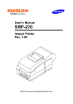
SRP-270
SERIES
1 STATION PRINTER
Operator’s Manual
All specifications are subjected to change without notice
Warning - U.S.
This equipment has been tested and found to comply with the limits for a Class A digital device
pursuant to Part 15 of the FCC Rules. These limits are designed to provide reasonable protection
against harmful interference when the equipment is operated in a commercial environment. This
equipment generates uses, and can radiate radio frequency energy and if not installed and used
according to the instruction manual, may cause harmful interference to radio communications.
Operation of this equipment in a residential area is likely to cause harmful interference in which
case the user will be required to correct the interference at his own expense.
Notice - Canada
This Apparatus complies with class “A” limits for radio interference as specified in the Canadian
department of communications radio interference regulations.
Get appareil est conforme aux normes class “A” d’interference radio tel que specifier par ministre
canadien des communications dans les reglements d’interference radio.
Caution
Some semiconductor devices are easily damaged by static electricity. You should turn the printer
“OFF”, before you connect or disconnect cables. This will help protect the printer against static
electricity. If the printer is damaged by the static electricity, you should turn the printer OFF, and
refer to your local service provider.
INTRODUCTION
The SRP-270 Roll Printers are designed for use with electronic instruments such as system ECR,
POS, banking equipment, computer peripheral equipment, etc.
The main features of the printer are as follows:
1.
2.
3.
4.
5.
High speed printing : 4.6 lines per seconds.
2 color dot-matrix printer.
RS-232C(SRP-270), RS-485 serial interface (SRP-270S), Parallel interface
(SRP-270P),USB interface(SRP-270U).
The data buffer allows the unit to receive print data even during printing.
Peripheral units drive circuit enables control of external devices such as cash
drawer.
Please be sure to read the instruction in this manual carefully before using your new
SRP-270 series.
NOTE : The power-outlet should be near the equipment and it
should be easy accessible.
2
Table of Contents
CHAPTER 1. UNPACKING ............................................................ 4
1-1. CHECKING THE CONTENTS OF THE PRINTER BOX.................................. 4
1-2. LOCATING THE PRINTER .............................................................. 4
1-3. FUNCTIONS............................................................................. 5
CHAPTER 2. CONNECTING THE CABLES ..................................... 6
2-1. CONNECTING THE AC ADAPTER TO THE PRINTER ................................. 6
2-2. CONNECTING INTERFACE CABLE AND DRAWER ................................... 7
CHAPTER 3. INSTALLING THE ROLL PAPER ............................... 8
3-1. RIBBON CASSETTE INSTALLATION .................................................. 8
3-2. ROLL PAPER INSTALLATION .......................................................... 9
CHAPTER 4. SETTING THE DIP SWITCHES............................... 13
CHAPTER 5. HEXADECIMAL DUMPING..................................... 16
CHAPTER 6. THE SELF TEST ...................................................... 17
CHAPTER 7. CODE TABLE.......................................................... 18
CHAPTER 8. CONTROL COMMANDS LIST ................................. 25
APPENDIX A .............................................................................. 29
CONNECTORS ................................................................................29
Interface Connector.................................................................30
Drawer Connector ...................................................................32
APPENDIX B .............................................................................. 33
SPECIFICATION ..............................................................................33
APPENDIX C .............................................................................. 34
REMOVING JAMMED PAPER ................................................................34
3
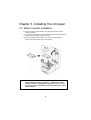
Chapter 1. Unpacking
1-1. Checking the Contents of the printer box
After unpacking the unit, check that all the necessary accessories are included in the
package.
1-2. Installing the printer
l
Avoid locations in direct sunlight or subject to excessive heat.
l
Avoid using or storing the printer in places subject to excessive moisture.
l
Do not use or store the printer in a dusty or dirty area. Avoid places subject to intense
vibration or shock.
l
Choose a stable and flat place for proper use of the printer.
l
Make sure that there is enough space around the printer so that it can be used easily.
4
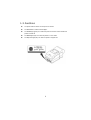
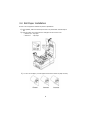
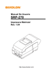
1-3. Functions
l
The power switch is used to turn the printer on and off.
l
The FEED button is used to feed roll paper.
l
The POWER light (green) is on when the printer is turned on and is off when the
l
The ERROR light (red) is on when the printer is in error state.
l
The Paper Out light(red) is on when the printer is in paper end.
printer is turned off.
5
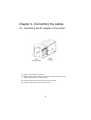
Chapter 2. Connecting the cables
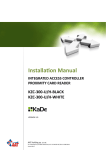
2-1. Connecting the AC adapter to the printer
1). Make sure that the printer is turned off.
2). CHECK the label on the AC adapter to make sure the voltage required by the AC
adapter matches that of your electrical outlet.
3). Plug the DC cord connector into the printer’s power connector.
4). Plug the AC adapter power cord into the wall outlet.
6
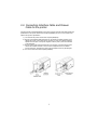
2-2. Connecting Interface Cable and Drawer
Cable to the printer
Connect the Host Computer(POS/ECR) to the printer using an interface cable that matches the
specifications of the printer and the Host computer(POS/ECR). Be sure to use a drawer that
matches the printer's specification.
1). Turn off both the printer and the Host computer(POS/ECR).
2). Plug the serial interface cable connector into the printer’s interface connector, then
tighten the screws on both sides of the connector. In case of the parallel interface,
squeeze the wire clips on the printer together until they lock in place on both sides
of the connector.
3). Plug the drawer cable into the drawer kick-out connector on the back of the printer
next to the interface connector. Do not connect a telephone line to the drawer
kick-out connector; otherwise the printer and the telephone line may be damaged
4). Turn on the Printer and Host computer(POS/ECR).
7
Chapter 3. Installing the roll paper
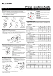
3-1. Ribbon Cassette Installation
1). Before inserting the ribbon cassette, turn the knob clockwise to prevent
twisting the ribbon.
2). Insert the ribbon cassette as shown below and pay particular attention to the
placement of the ribbon behind the Print Head.
3). During inserting the ribbon cassette, turn the knob clockwise again to
make sure the ribbon moves freely in the cassette.
NOTE : Malfunctions and other problems may arise if other than specified
ribbon cassettes are used in the printer. The Warranty may be
voided if other than specified ribbon cassettes are used. Contact
your dealer or place of purchase for more information about proper
ribbon cassettes.
8
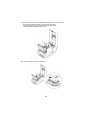
3-2. Roll Paper Installation
Be sure to use roll paper that matches the printer's specifications.
1). When possible, make sure that the printer has no un-printed data. This data may be
lost.
2). Open the printer cover and remove the used paper roll core if there is one.
" SRP-270 A/C : 1Ply Paper
# SRP-270 D
: 2Ply Paper
3). To use a new roll paper, unroll the paper and tear off the end of the paper correctly.
9
4). Put the roll paper on the paper holder and insert the paper in the printer.
" SRP-270 A/C : 1Ply Paper
# SRP-270 D
: 2Ply Paper
10
5) Insert the end of the roll paper straight into the paper inlet. The printer feeds
the paper automatically and then the printer will cut the paper
automatically(SRP-270C type series and SRP-270D type series).
Refer to the attached label inside the cover.
6). Tear off the paper as shown, if necessary.
11
7). Insert the end of the roll paper into the groove on the Roller-Pulley, warp the paper
around it two or three times and load the Roller-Pulley onto the groove of the
Case.
8). Push the auto-cutter cover as shown below and close the printer cover.
NOTE : Push upper face of the auto cutter cover for completely locking of it.
9). When the ERROR light is on and PAPER OUT light blinks, please press the FEED
button. After that, the printer is ready for printing.
12
Chapter 4. Setting the DIP switches
The DIP switches are located on the bottom of the printer. The DIP switches are used to set the
printer to perform various functions. Follow these steps when changing DIP switch settings :
1.
Turn the printer power switch off.
2.
Turn the printer over and remove the dip switch cover.
3.
Move the DIP switches using tweezers or another narrow-ended tool. Switches
are on when up and off when down in the figure below.
4.
The new setting takes effect when you turn on the printer.
NOTE : Always change DIP switch settings when the printer is turned off.
Changes made with the power on have no effect until you turn the
printer off and then on again.
13
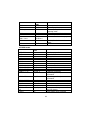
Serial Interface (RS-232C/RS-485) Specification
DIP Switch 1 Setting
SW
1
2
3
4
5
6
7
8
FUNCTION
Emulation Selection
Auto-Cutter
FONT SPACE
Function for
service
Engineer
RESERVED
ON
OFF
Refer to the following table
Enable
2
Disable
3
DEFAULT
OFF
OFF
OFF
OFF
OFF
OFF
Emulation mode selection
SW – 1
OFF
OFF
ON
SW – 2
OFF
ON
OFF
MODE
Epson
Citizen
Star
Dip Switch 2 Setting
SW
1
2
3
4
5
6
7
8
FUNCTION
Data Receive Error
Hexadecimal dump
Hand Shaking
Word length
Parity check
Parity selection
Baud Rate selection
ON
Print ”?”
YES
XON/OFF
7 bits
Enable
EVEN
OFF
Ignore
NO
DTR/DSR
8 bits
Disable
ODD
Refer to the following table
DEFAULT
OFF
OFF
OFF
OFF
OFF
OFF
OFF
OFF
Baud rate selection
Transmission speed
1200 baud
2400 baud
4800 baud
9600 baud
SW – 7
ON
OFF
ON
OFF
SW – 8
ON
ON
OFF
OFF
NOTE : When the word length is 7 bits, you can not parity check OFF status.
14
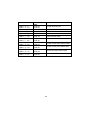
Parallel/USB Interface Specification
DIP Switch 1 Setting
SW
1
2
3
4
5
6
7
8
FUNCTION
Emulation Selection
Auto-Cutter
FONT SPACE
Function for
service
Engineer
RESERVED
ON
OFF
Refer to the following table
Enable
2
Disable
3
DEFAULT
OFF
OFF
OFF
OFF
OFF
OFF
Emulation mode selection
SW – 1
OFF
OFF
ON
SW – 2
OFF
ON
OFF
MODE
Epson
Citizen
Star
Dip Switch 2 Setting
SW
1
2
3
4
5
6
7
8
FUNCTION
Reserved
Hex Dump
Reserved
Reserved
Reserved
Reserved
Reserved
Reserved
ON
YES
-
OFF
NO
-
15
DEFAULT
OFF
OFF
OFF
OFF
OFF
OFF
OFF
OFF
Chapter 5. Hexadecimal Dumping
This feature allows experienced users to see exactly what data is coming to the printer. This can
be useful in finding software problems. When you turn on the hexadecimal dump function, the
printer prints all commands and data in hexadecimal format along with a guide section to help
you find specific commands.
To use the hexadecimal dump function, follow these steps:
1. After you make sure that the printer is off.
2. Set DIP switch 2-2 On.
3. Turn on the printer, then the printer enters the hexadecimal dump mode.
4. Run any software program that sends data to the printer. The printer will print all the
codes it receives in a two-column format. The first column contains the hexadecimal
codes and the second column gives the ASCII characters that correspond to the
codes.
1B 21 00 1B 26 02 40 40
02 0D 1B 44 0A 14 1E 28
00 01 0A 41 0D 42 0A 43
.!..&.@@
...D....(
...A.B.C
l
A period(.) is printed for each code that no ASCII equivalent.
l
During the hex dump, all commands except DLE EOT and DLE ENQ are
disabled.
l
Insufficient print data to fill the last line can be printed by pressing the feed
button.
5. When the printing finishes, turn off the printer, and then change DIP switch 2-2 OFF.
6. Turn on the printer and then the hexadecimal mode is off.
16
Chapter 6. The self test
The self-test checks whether the printer has any problems. If the printer does not function
properly, contact your dealer.
1.
Make sure paper roll has been installed properly.
2.
Turn on the power while holding down the FEED button. The self-test begins.
3.
The self-test prints the current printer status, which provides the control ROM
version and the DIP switch setting.
4.
After printing the current printer status, self-test printing will print the following,
and pause (The PAPER LED light blinks).
Self-test printing.
Please press the FEED button
5.
Press the FEED button to continue printing. The printer prints a pattern using the
built-in character set.
6.
The self-test automatically ends after printing the following.
** Character Test Completed **
The printer is ready to receive data when it completes the self-test.
17
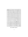
Chapter 7. Code Table
The following pages show the character code tables. To find the character corresponding to a
hexadecimal number, count across the top of the table for the left digit and count down the left
column of the table for the right digit. For example, 4A = J.
Page 0 ( PC437 : USA, Standard Europe)
( International Character Set : USA )
18
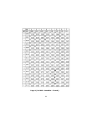
Page 2 ( PC850 : Multilingual )
19
Page 3 ( PC860 : Portuguese )
20
Page 4 ( PC 863 : Canadian - French )
21
Page 5 ( PC 865 : Nordic )
22
Page 19 ( PC 858 : Euro )
23
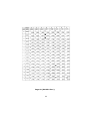
International Character
24
Chapter 8. Control Commands List
EPSON mode
Control code
Hexadecimal
code
Function
<HT>
<LF>
<CR>
<DLE> <EOT> n
<DLE> <ENQ> n
<ESC> <SP> n
<ESC> ! n
<ESC> % n
09
0A
0D
10 04 n
10 05 n
1B 20 n
1B 21 n
1B 25 n
<ESC> & y c1 c2 ..
<ESC> * m nL nH ..
<ESC> - n
<ESC> 2
<ESC> 3 n
<ESC> <
<ESC> = n
<ESC> ? n
<ESC> @
<ESC> D n1 ~ nK
<ESC> E n
<ESC> G n
<ESC> J n
<ESC> K n
<ESC> R n
1B
1B
1B
1B
1B
1B
1B
1B
1B
1B
1B
1B
1B
1B
1B
<ESC> U n
1B 55 n
<ESC> a n
<ESC> c 3 n
1B 61 n
1B 63 33 n
<ESC> c 4 n
1B 63 34 n
<ESC>
<ESC>
<ESC>
<ESC>
1B
1B
1B
1B
Horizontal tab
Print and line feed
Print and carriage return
Real-time status transmission
Real-time request to printer
Set right-side character spacing
Select print modes
Select/Cancel user-defined
character set
Define user-defined characters
Select bit-image mode
Turn underline mode on/off
Select default line spacing
Set line spacing
Return home
Set peripheral device
Cancel user-defined characters
Initialize printer
Set horizontal tab position
Turn emphasized mode on/off
Turn double-strike mode on/off
Print and feed paper
Print and Reverse feed
Select an international character
set
Turn unidirectional printing
mode
Select justification
Select paper sensor to output
paper end signals
Select paper sensor to stop
printing
Enable/Disable panel button
Print and feed n lines
Generate pulse
Select character code table
c5n
dn
p m t1 t2
tn
26 y c1 c2
2A m nL nH
2D n
32
33 n
3C
3D n
3F n
40
44 … 00
45 n
47 n
4A n
4B n
52 n
63
64
70
74
35 n
n
m t1 t2
n
25
Control code
Hexadecimal
code
Function
<ESC> r n
<ESC> m
<ESC> { n
1B 72 n
1B 6D
1B 7B n
<ESC> e n
<GS> I n
<GS> V m
<GS> V m n
<GS> a n
1B 65 n
1D 49 n
1D 56 m
1D 56 m n
1D 61 n
Select print color
Execute partial cut
Turn on/off upside-down
printing mode
Print and reverse feed n lines
Transmit printer ID
Select cut mode and cut paper
<GS> r n
1D 72 n
Enable/Disable Automatic status
back
Transmit status
CITIZEN mode
Control code
Hexadecimal
code
Function
<FF> "n"
<LF>
<SO>
<SI>
<DC1>
<DC2>
<DC3>
<CAN>
<ESC> "P" "0"
<ESC> "P" "1"
<ESC> "-" "n"
<ESC> "1"
0C + n
OA
0E
0F
11
12
13
18
1B, 50, 00
1B, 50, 01
1B, 2D, n
1B, 31
<ESC> "2"
1B, 32
<ESC> "C" "n"
<ESC> "f" "1"
<SUB>
<FS>
<ESC><BEL> n1
n2
<BEL>
1B, 43, n
1B, 66, 01
1A
1C
1B, 07, n1, n2
"n" -lines paper feed command
Paper feed command
Enlarged character command
Normal character command
Initial set command
Inverted character command
Red color print command
Clear command
Paper partial cut command
Paper partial cut command
Underline command
1/9 inch paper feed preset
command
2/9 inch paper feed preset
command
Page length set command
Form feed command
Second drawer drive command
First drawer quick drive command
Drive pulse setting command for
the first drawer
First drawer drive command
07
26
STAR mode
Control code
Hexadecimal
code
Function
<ESC> "C" n
<ESC> "R" n
<ESC> "M"
<SO>
<SI>
<DC2>
<DC4>
1B 43 n
1B 52 n
1B 4D
0E
0F
12
14
<ESC>
<ESC>
<ESC>
<ESC>
<ESC>
<ESC>
<ESC>
<ESC>
1B
1B
1B
1B
1B
1B
1B
1B
Set page length at n lines
Select international character set.
Select 9×7(Half dots) character size
Select expanded character mode
Select upside-down
Cancel upside-down character
Cancel expanded character
mode(Default setting)
Select expanded character mode
"W"
"W"
"W"
"W"
"4"
"5"
"E"
"F"
"1"
<1>
"0"
<0>
57
57
57
57
34
35
45
46
31
01
30
00
<ESC> "a" n
<ESC><BEL>n1
n2
<BEL>
1B 61 n
1B 07 n1 n2
<FS>
1C
<SUB>
1A
<EM>
19
<CAN>
<ESC> "@"
<ESC> "e" "0"
<ESC> "e" <0>
<ESC> "e" "1"
<ESC> "e" <1>
<ESC> U n
<ESC> - n
18
1B
1B
1B
1B
1B
1B
1B
07
40
65 30
65 00
65 31
65 01
55 n
2D n
Cancel expanded character mode
(Default setting)
Red color print selection
Red color print deselection
Emphasized print mode selection
Emphasized print mode deselection
(Default setting)
Feed paper n lines
Adjust drive pulse width for
peripheral unit(Default setting)
Deferred drive command "A" for
peripheral unit 1
Immediate drive command "B" for
peripheral unit 1
Immediate drive command for
peripheral unit 2
Immediate drive command for
peripheral unit 2
Cancel print data in buffer
Initialize printer
FEED switch valid
(Default setting)
FEED switch invalid
Set or Cancel uni-direction mode
Set or Cancel underline mode
27
Control code
Hexadecimal
code
Function
<ESC>
<ESC>
<FF>
<ESC>
<ESC>
<ESC>
<ESC>
<ESC>
<ESC>
<ESC>
<ESC>
<ESC>
<ESC>
<ESC>
<ESC>
<ESC>
<ESC>
1B
1B
0C
1B
1B
1B
1B
1B
1B
1B
1B
1B
1B
1B
1B
1B
1B
Set 1/6 inch line feed
"z" "1"
"z" <1>
d "0"
d "1"
"-" "1"
"-" <1>
"-" "0"
"-" <0>
"e" "1"
"e" <1>
"e" "0"
"e" <0>
"f" "1"
"f" <1>
"f" "0"
"f" <0>
7A 31
7A 01
64 30
64 31
5F 31
5F 01
5F 30
5F 00
65 31
65 01
65 30
65 00
66 31
66 01
66 30
66 00
Page feed (form feed)
Partial cut
Partial cut
Select overline mode
Cancel overline mode
Set the control panel switch invalid
Set the control panel switch valid
Set the ON LINE switch invalid
Set the ON LINE switch valid
28
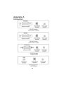
Appendix A
Connectors
29
Interface Connector
Serial Interface(RS-232C)
Pin No.
Signal name
Direction
Function
1
FG
-
Frame Ground
2
TxD
Output
Transmit Data
3
RxD
Input
Receive Data
6
DSR
Input
Data Set Ready
7
SG
-
Signal Ground
20
DTR
Output
Data Terminal Ready
Serial Communication Interface(Example)
Printer
SG
TXD
RSD
DSR
DTR
Host(DTE ex 8251)
SG
TXD
RSD
RTS
CTS
DSR
DTR
S.G
S.G
Serial Interface(RS-485)
Pin No.
Signal Name
Direction
Function
1
FGND
-
Frame Ground
2
SD2
Output
3
SD1
Output
4
RD2
Input
5
RD1
Input
7
SGND
-
Signal Ground
8
DR2
9
DR1
Output
Same as DTR(RS-232)
10
CS2
11
CS1
Input
Same as DSR(RS-232)
30
Send Data
Receive Data
Parallel Interface(IEEE-1284)
Pin No. Source
Compatibility
Mode
Nibble
Mode
Byte Mode
1
Host
nStrobe
HostClk
HostClk
2
Host / Printer
Data 0 (LSB)
-
Data 0 (LSB)
3
Host / Printer
Data 1
-
Data 1
4
Host / Printer
Data 2
-
Data 2
5
Host / Printer
Data 3
-
Data 3
6
Host / Printer
Data 4
-
Data 4
7
Host / Printer
Data 5
-
Data 5
8
Host / Printer
Data 6
-
Data 6
9
Host / Printer
Data 7 (MSB)
-
Data 7 (MSB)
10
Printer
nAck
PtrClk
PtrClk
11
Printer
Busy
PtrBusy
/Data3,7
PtrBusy
12
Printer
Perror
AckDataReq
/Data2,6
AckDataReq
13
Printer
Select
Xflag
/Data1,5
Xflag
14
Host
nAutoFd
HostBusy
HostBusy
15
-
NC
NC
NC
16
-
GND
GND
GND
17
-
FG
FG
FG
18
Printer
Logic-H
Logic-H
Logic-H
19~30
-
GND
GND
GND
31
Host
nInit
nInit
nInit
32
Printer
nFault
nDataAvail
/Data0,4
nDataAvail
33
-
GND
ND
ND
34
Printer
DK_Status
ND
ND
35
Printer
+5V
ND
ND
36
Host
nSelectIn
1284-Active
1284-Active
31
USB Interface
Pin No.
Signal Name
Assignment
Function
(Color)
Shell
Shield
Drain Wire
Frame Ground
1
VBUS
Red
Host Power
2
D-
White
Data Line(D-)
3
D+
Green
Data Line(D+)
4
GND
Black
Signal Ground
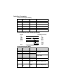
Drawer Connector
Pin No.
Signal name
Direction
1
Frame ground
-
2
Drawer kick-out drive signal 1
Output
3
Drawer open/close signal
Input
4
+24V
-
5
Drawer kick-out drive signal 2
Output
6
Signal ground
-
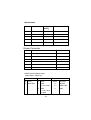
* SRP-270 Series Model Listing
Model Name : SRP-27xyz
x
y
z
0
Ivory
A
Basic
Blank
RS-232C
5
Dark Gray
C
Basic
S
RS-485
+ Auto cutter
P
IEEE-1284
Basic
U
USB
D
+ Auto cutter
+ Spool
32
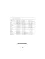
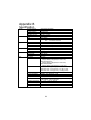
Appendix B
Specification
Printer
Ribbon
Paper
Adapter
Auto Cutter
ETC
Printing method
Number of head pin
Printing direction
Lines per second
Characters per line
Ribbon type
Color
Ribbon life
Paper type
Paper width
Roll diameter
Thickness
Overall dimensions
Weight
Types
Cutter type
Cutting width
Cutting thickness
Data buffer
Overall dimension
Weight
Rating
Power consumption
EMI
Safety standards
Reliability
Operation temperature
Operation humidity
Storage temperature
Storage humidity
Serial impact dot matrix
9 wires
Bi-directional
Approx. 4.6 LPS
40 (9*7), 33(9*9)
Cartridge type (ERC-38 Black/Red)
Black & Red
Approx. Black : 1.5 Million characters
Red : 0.75 Million characters
Roll paper
W76mm ¡ ¾0.5mm (2.99" ¡ ¾0.22")
Max. φ80mm (3.14")
0.06mm ~ 0.085mm (0.002" ~ 0.003")
120mm * 63mm * 33mm ( 4.71" * 2.47" * 1.29" )
215gr ( 0.5 lbs)
AD-270 Free Voltage (50Hz ~ 60Hz)
Gillotine type
Max. 85 mm
Max. 0.1mm
4k bytes
SRP-270A/AS/AP/AU :
160(W)*249(D)*130(H)mm(6.3"*9.8"*5.12")
SRP-270C/CS/CP/CU :
160(W)*249(D)*149(H)mm(6.3"*9.8"*5.87")
SRP-270D/DS/DP/DU :
160(W)*294(D)*160(H)mm(6.3"*11.57"*6.3")
Weight(printer only) / Weight(with box & accessories ) :
SRP-270A TYPE : 2.2 Kg (4.9 lbs) / 3.2 Kg (7.1 lbs)
SRP-270C TYPE : 2.5 Kg (5.5 lbs) / 3.5 Kg (7.7 lbs)
SRP-270D TYPE : 2.6 Kg (5.7 lbs) / 3.6 Kg (7.9 lbs)
DC 24 V, 1.0 A
Standby : 8 W, Operation : 24 W
FCC class A, CE
UL/CSA, TUV
Printer MCBF : 7,500,000 lines (Except print head life )
Print head life : 300,000,000 Dots
0¡ É~ 40¡ É( 32¢ µ~ 104¢ µ)
30% ~ 80%
-5¡ É~ 50¡ É( 23¢ µ~ 122¢ µ)
10% ~ 95%
33
Appendix C
Removing Jammed Paper
1) Open the printer cover
2) Raise the auto cutter unit by lifting the knob lock.
3) Remove the ribbon cassette.
4) Loosen the manual screw.
5) Remove the head cover.
CAUTION : The printer head becomes very hot during printing.
Allow it to be cool before you reach into the printer.
34
6) Move the print head carriage to the reverse direction of paper jam.
7)
the side of the print head as shown in the illustration.
Remove the jammed paper by rotating the paper-feed knob.
By pushing on
8) Replace the head cover and secure it with screw.
9) Replace the ribbon cassette and roll paper, then close the printer cover.
35
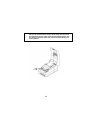
NOTE : If you are troubled with reloading the paper, the cutter blade may
not be in its normal position. Insert a screw driver into the hole at
the bottom side of auto cutter unit as shown followed picture, and
turn the gear inside the cutter unit to move the cutter blade to its
normal position.
36