1
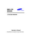
SRP-250
SERIES
1 STATION PRINTER
Operator’s Manual
All specifications are subjected to change without notice
Warning - U.S.
This equipment has been tested and found to comply with the limits for a Class A digital device
pursuant to Part 15 of the FCC Rules. These limits are designed to provide reasonable
protection against harmful interference when the equipment is operated in a commercial
environment. This equipment generates uses, and can radiate radio frequency energy and if
not installed and used according to the instruction manual, may cause harmful interference to
radio communications. Operation of this equipment in a residential area is likely to cause
harmful interference in which case the user will be required to correct the interference at his
own expense.
Notice - Canada
This Apparatus complies with class “A” limits for radio interference as specified i n the
Canadian department of communications radio interference regulations.
Get appareil est conforme aux normes class “A” d’interference radio tel que specifier par
ministre canadien des communications dans les reglements d’interference radio.
Caution
Some semiconductor devices are easily damaged by static electricity. You should turn the
printer “OFF”, before you connect or remove the cables on the rear side, in order to guard the
printer against the static electricity. If the printer is damaged by the static electricity, you should
turn the printer “OFF”.
INTRODUCTION
The SRP-250 and SRP-250P Roll Printer are designed for use with electronic instruments
such as system ECR, POS, banking equipment, computer peripheral equipment, etc.
The main features of the printer are as follows:
1.
2.
3.
4.
5.
6.
7.
8.
High speed printing : 3.5 lines per seconds.
2 color dot-matrix printer.
RS-232 serial interface (SRP-250). Parallel interface (SRP-250P)
The data buffer allows the unit to receive print data even during printing.
Peripheral units drive circuit enables control of external devices such as
cash drawer.
Characters can be scaled up to 64 times compared to it’s original size.
Bar code printing is possible by using a bar code command.
Different print densities can be selected by DIP switches.
Please be sure to read the instruction in this manual carefully before using your new
SRP-250/SRP-250P.
NOTE : The socket-outlet shall be near the equipment and it
shall be easy accessible.
Table of Contents
CHAPTER 1. UNPACKING...................................................................3
1-1. CHECKING THE CONTENTS OF THE PRINTER BOX ...............................3
1-2. LOCATING THE PRINTER .................................................................3
1-3. FUNCTIONS ..................................................................................4
CHAPTER 2. CONNECTING THE CABLES.........................................5
2-1. CONNECTING THE AC ADAPTER TO THE PRINTER ..............................5
2-2. CONNECTING INTERFACE CABLE AND DRAWER
CABLE TO THE PRINTER ................................................................6
CHAPTER 3. INSTALLING THE ROLL PAPER ...................................7
3-1. RIBBON CASSETTE INSTALLATION ...................................................7
3-2. ROLL PAPER INSTALLATION ............................................................8
CHAPTER 4. SETTING THE DIP SWITCHES .................................... 12
CHAPTER 5. HEXADECIMAL DUMPING........................................... 15
CHAPTER 6. THE SELF TEST........................................................... 16
CHAPTER 7. CODE TABLE ............................................................... 17
CHAPTER 8. CONTROL COMMANDS............................................... 22
APPENDIX A ...................................................................................... 39
CONNECTORS .................................................................................... 39
Interface Connector ...................................................................... 40
Drawer Connector ........................................................................ 42
APPENDIX B ...................................................................................... 43
SPECIFICATION .................................................................................. 43
APPENDIX C ...................................................................................... 44
REMOVING JAMMED PAPER (A)............................................................ 44
REMOVING JAMMED PAPER (B)............................................................ 46
2
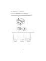
Chapter 1. Unpacking
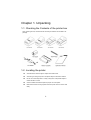
1-1. Checking the Contents of the printer box
After unpacking the unit, check that all the necessary accessories are included in the
package.
1-2. Locating the printer
l
Avoid locations in direct sunlight or subject to excessive heat.
l
Avoid using or storing the printer in the places subject to excessive moisture.
l
Do not use or store the printer in a dusty or dirty area. Avoid places subject to
intense vibration or shock.
l
Choose a stable and horizontal place for proper use of the printer.
l
Make sure that there is enough space around the printer so that it can be used
easily.
3
1-3. Functions
l
The power switch is used to turn the printer on and off.
l
The FEED button is used to feed roll paper.
l
The POWER light (green) is on when the printer is turned on and is off when the
printer is turned off.
l
The ERROR light (red) is on when the printer cover is opened.
4
Chapter 2. Connecting the cables
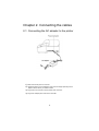
2-1. Connecting the AC adapter to the printer
1). Make sure that the printer is turned off.
2). CHECK the label on the AC adapter to make sure the voltage required by the AC
adapter matches that of your electrical outlet.
3). Plug the DC cord connector into the printer’s power connector.
4). Plug the AC adapter power cord into the wall outlet.
5
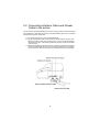
2-2. Connecting Interface Cable and Drawer
Cable to the printer
Connect the Host Computer(POS/ECR) to the printer using an interface cable that matches
the specifications of the printer and the Host computer(POS/ECR). Be sure to use a drawer
that matches the printer's specification.
1). Turn off the printer and the Host computer(POS/ECR).
2). Plug the serial interface cable connector into the printer’s interface connector, then
tighten the screws on both sides of the connector. In case of the parallel interface,
squeeze the wire clips on the printer together until they lock in place on both sides
of the connector.
3). Plug the drawer cable into the drawer kick-out connector on the back of the printer
next to the serial/parallel connector. Do not connect a telephone line to the drawer
kick-out connector; otherwise the printer and the telephone line may be damaged.
6
Chapter 3. Installing the roll paper
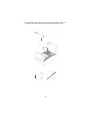
3-1. Ribbon Cassette Installation
1). Before inserting the ribbon cassette, turn the knob counterclockwise to prevent
twisting the ribbon.
2). Insert the ribbon cassette as shown below and pay particular attention to the
placement of the ribbon behind the Print Head.
3). During inserting the ribbon cassette, turn the knob counterclockwise again to
make sure the ribbon moves freely in the cassette.
NOTE : Malfunctions and other problems may arise if other than the ribbon
cassette samsung supplied is used. Samsung does not warrant
against problems arising from the use of other than the ribbon
cassette samsung supplied
7
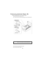
3-2. Roll Paper Installation
Be sure to use roll paper that matches the printer's specifications.
1). Make sure that the printer has no received data. Otherwise, data may be lost.
2). Open the printer cover and remove the used paper roll core if there is one.
3). To use a new roll paper, unroll the paper and tear off the end of the paper correctly.
8
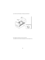
4). Insert the Shaft-Pulley into the hole of roll paper core and load the roll paper on
the paper holder. Don't forget to turn the printer's POWER on at this time.
9
5). Insert the end of the roll paper straight into the paper inlet. The printer feeds
the paper automatically(All SRP-250 model) and then the printer will cut the paper
automatically(SRP-250C/CP and SRP-250D/DP only).
6). Tear off the paper as shown, if necessary.
10
7). Insert the end of the roll paper into the groove on the Roller-Pulley and wrap
the paper around the spool two or three times.
8). Load the Roller-Pulley onto the groove of the Guide-Pulley.
9). Close the printer cover.
11
Chapter 4. Setting the DIP switches
The DIP switches are located on the bottom of the printer. The DIP switches are used to set
the printer to perform various functions. Follow these steps when changing DIP switch
settings :
1.
Turn the printer power switch off.
2.
Turn the printer over and remove the dip switch cover.
3.
Flip the DIP switches using tweezers or another narrow-ended tool. Switches
are on when up and off when down in the figure below.
4.
The new setting takes effect when you turn on the printer.
NOTE : Always change DIP switch settings when the printer is turned off. Changes made
with the power on have no effect until you turn the printer off and then on again.
12
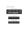
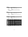
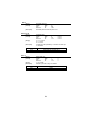
Serial Interface Specification
DIP Switch 1 Functions
SW
1
2
3
4
5
6
7
8
l
FUNCTION
Data Receive Error
Hand Shaking
Word length
Parity check
Parity selection
Baud Rate selection
ON
OFF
Ignore
Print ¡ °?¡ ±
XON/OFF
DTR/DSR
7 bits
8 bits
Yes
No
EVEN
ODD
Refer to the following table
Hexadecimal dump
NOTE
:
ON
OFF
DEFAULT
OFF
OFF
OFF
OFF
OFF
OFF
OFF
OFF
When the word length is 7 bits, you can not parity check OFF status.
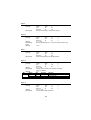
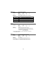
Baud rate selection
Transmission speed
1200 baud
2400 baud
4800 baud
9600 baud
SW – 6
ON
OFF
ON
OFF
SW – 7
ON
ON
OFF
OFF
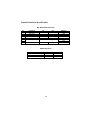
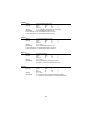
DIP Switch 2 Functions
MODE
Epson
Citizen
Star
SW – 1
OFF
ON
OFF
13
SW – 2
OFF
OFF
ON
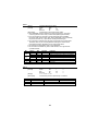
Parallel Interface Specification
Dip Switch Set Function
SW
1
2
3
4
5
6
7
8
FUNCTION
Reserved
Reserved
Reserved
Reserved
Reserved
Mode Selection
Hex Dump
ON
OFF
Refer to the following table
ON
OFF
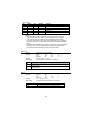
Mode Selection
MODE
Epson
Star
Citizen
SW – 6
OFF
ON
OFF
14
SW – 7
OFF
OFF
ON
DEFAULT
OFF
OFF
OFF
OFF
OFF
OFF
OFF
OFF
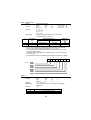
Chapter 5. Hexadecimal Dumping
This feature allows experienced users to see exactly what data is coming to the printer. This
can be useful in finding software problems. When you turn on the hexadecimal dump function,
the printer prints all commands and data in hexadecimal format along with a guide section to
help you find specific commands.
To use the hexadecimal dump function, follow these steps:
1.
After you make sure that the printer is off.
2.
Set DIP switch 8 to On.
3.
Turn on the printer, then the printer enters the hexadecimal dump mode.
4.
Run any software program that sends data to the printer. The printer will print all the
codes it receives in a two-column format. The first column contains the hexadecimal
codes and the second column gives the ASCII characters that correspond to the codes.
1B 21 00 1B 26 02 40 40
02 0D 1B 44 0A 14 1E 28
00 01 0A 41 0D 42 0A 43
.!..&.@@
...D....(
...A.B.C
l
A period(.) is printed for each code that no ASCII equivalent.
l
During the hex dump, all commands except DLE EOT and DLE ENQ are
disabled.
l
Insufficient print data to fill the last line can be printed by pressing the feed
button.
5.
When the printing finishes, turn off the printer, and then change DIP switch 8 to OFF.
6.
Turn on the printer and then the hexadecimal mode is off.
15
Chapter 6. The self test
The self-test checks whether the printer has any problems. If the printer does not function
properly, contact your dealer. The self-test checks the following;
1.
Make sure paper roll has been installed properly.
2.
Turn on the power while holding down the FEED button. The self-test begins.
3.
The self-test prints the current printer status, which provides the control ROM
version and the DIP switch setting.
4.
After printing the current printer status, self-test printing will print the following,
and pause (The PAPER LED light blinks).
Self-test printing.
Please press the FEED button
5.
Press the FEED button to continue printing. The printer prints a pattern using
the built-in character set.
6.
The self-test automatically ends and cuts the paper after printing the
following.
*** completed ***
The printer is ready to receive data when it completes the self-test.
16
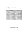
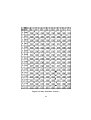
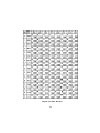
Chapter 7. Code Table
The following pages show the character code tables. To find the character corresponding to a
hexadecimal number, count across the top of the table for the left digit and count down the left
column of the table for the right digit. For example, 4A = J.
Page 0 ( PC437 : USA, Standard Europe)
( International Character Set : USA )
17
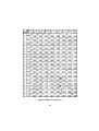
Page 2 ( PC850 : Multilingual )
18
Page 3 ( PC860 : Portuguese )
19
Page 4 ( PC 863 : Canadian - French )
20
Page 5 ( PC 865 : Nordic )
21
International Character
22
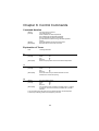
Chapter 8. Control Commands
Command Notation
[Name]
[Format]
[Range]
[Description]
The name of the command.
The code sequence.
ASCII indicates the ASCII equivalents.
Hex indicates the hexadecimal equivalents.
Decimal indicates the decimal equivalents.
[ ] k indicates the contents of the [ ] should be repeated
k times.
Gives the allowable ranges for the arguments.
Describes the function of the command.
Explanation of Terms
LSB
Least Significant Bit
[Name]
[Format]
Horizontal tab.
ASCII
HT
Hex
09
Decimal
9
Moves the print position to the next horizontal tab position.
HT
[Description]
LF
[Name]
[Format]
[Description]
Print and line feed.
ASCII
LF
Hex
0A
Decimal
10
Prints the data in the print buffer and feeds one line
based on the current line spacing.
CR
[Name]
[Format]
Print and carriage return.
ASCII
CR
Hex
0D
Decimal
13
[Description]
This command is set according to the DIP switch 1-1 setting
at power-on. This command is only available with a parallel
interface.
• This command prints the data in the print buffer and does not feed the paper.
• Sets the print starting position to the beginning of the line.
23
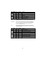
DLE EOT n
[Name]
[Format]
Real-time status transmission.
ASCII
DLE
EOT
n
Hex
10
04
n
Decimal
16
4
n
1≤n≤4
Transmits the selected printer status specified by n
in real time, according to the following parameters:
n = 1 : Transmit printer status.
n = 2 : Transmit off-line status.
n = 3 : Transmit error status.
n = 4 : Transmit paper roll sensor status.
[Range]
[Description]
n = 1 : Printer status
Off/On
Hex
Bit
0
Off
00
1
On
02
2
Off
00
3
4
5
6
7
On
04
4
Off
On
On
Off
On
Off
00
08
10
00
20
00
0
8
16
0
32
0
n = 2 : Off-line status
Bit
Off/On
Hex
0
Off
00
1
On
02
2
3
Off
00
4
5
6
7
Decimal
0
2
0
Decimal
0
2
0
On
08
8
On
Off
On
Off
On
Off
10
00
20
00
40
00
16
0
32
00
64
00
Function
Not used. Fixed to Off.
Not used. Fixed to On.
Drawer open/close signal is LOW
(connector pin 3).
Drawer open/close signal is HIGH
(connector pin 3).
On-Line.
Off-Line.
Not used. Fixed to On.
Not waiting for on-line recovery.
Waiting for on-line recovery.
Undefined.
Not used. Fixed to Off.
Function
Not used. Fixed to Off.
Not used. Fixed to On.
Undefined.
Paper is not being fed by using the PAPER
FEED button.
Paper is being fed by the PAPER FEED
button.
Not used. Fixed to On.
No paper-end stop.
Printing stops due to paper end.
No error.
Error occurs.
Not used. Fixed to Off.
24
n = 3 : Error status
Off/On
Bit
0
Off
1
On
2
Off
On
3
4
On
6
Off
On
7
Off
Bit 2:
Hex
00
02
00
04
10
00
40
00
Decimal
0
2
0
4
16
0
64
0
Function
Not used. Fixed to Off.
Not used. Fixed to On.
No mechanical error.
Mechanical error occurred.
Undefined.
Not used. Fixed to On
No auto-recoverable error.
Auto-recoverable error has occurred.
Not used. Fixed to Off.
Mechanical errors include home position, carriage sensor, and slip
ejection errors.
Bits 2 and 3:
If these errors occur due to paper jams or the like, it is possible to
recover by correcting the cause of the error and executing DLE ENQ
n (1 ≤ n ≤ 2). If an error due to a circuit failure (e.g. broken wire)
occurs, it is impossible to recover.
Bit 6:
If the print head temperature becomes high, bit 6 is transmitted until
the print head temperature drops sufficiently. The printer automatically
recovers from this error.
n = 4 : Continuous paper sensor status
Off/On
Hex
Decimal
Bit
0
Off
00
0
1
On
02
2
2
Off
00
0
On
04
4
3
Off
00
0
On
08
8
4
On
10
16
5
Off
00
0
On
20
32
6
On
00
0
On
40
64
7
Off
00
0
Function
Not used. Fixed to off.
Not used. Fixed to On.
Paper roll end sensor. Paper adequate.
Paper roll end sensor. Paper end.
Paper roll end sensor. Paper adequate.
Paper roll end sensor. Paper end.
Not used. Fixed to On.
Paper roll end sensor. Paper present.
Paper roll end sensor. No paper.
Paper roll end sensor. Paper present.
Paper roll end sensor. No paper.
Not used. Fixed to Off.
25
DLE ENQ n
[Name]
[Format]
Real-time request to printer.
ASCII
DLE
ENQ
n
Hex
10
05
n
Decimal
16
5
n
[Range]
1≤n≤2
[Description]
Recovers from an error after clearing the receive and
print buffers.
• This command is available only with a serial interface, and is ignored with
a parallel interface.
ESC SP n
[Name]
[Format]
[Range]
[Description]
Set right-side character spacing.
ASCII
ESC
SP
n
Hex
1B
20
n
Decimal
27
32
n
0 ≤ n ≤ 255
Sets the character spacing for the right side of the character
to n/160 inches.
ESC ! n
[Name]
[Format]
[Range]
[Description]
Bit
0
1,2
3
4
5
6
7
Off/On
Off
On
Off
On
Off
On
Off
On
Off
On
Select print mode(s).
ASCII
ESC
!
n
Hex
1B
21
n
Decimal
27
33
n
0 ≤ n ≤ 255
Selects print mode(s) using n as follows.
Hex
00
01
00
08
00
10
00
20
00
80
Decimal
0
1
0
8
0
16
0
32
0
128
Function
Character font(9 × 9) selected.
Character font(9 × 7) selected.
Undefined.
Emphasized mode not selected.
Emphasized mode selected.
Double-height mode not selected.
Double-height mode selected.
Double-width mode not selected.
Double-width mode selected.
Undefined.
Underline mode not selected.
Underline mode selected.
• Determine the values of n by adding the value of all the characteristics
you want to select.
26
ESC % n
[Name]
[Format]
[Range]
[Description]
Select/Cancel user-defined character set.
ASCII
ESC
%
n
Hex
1B
25
n
Decimal
27
37
n
0 ≤ n ≤ 255
Selects or cancels the user-defined character set.
When the Least Significant Bit(LSB) is 0, the user-defined
character set is canceled and the internal character set
is enabled.
When the LSB is 1, the user-defined character set is selected.
[Notes]
• The user-defined character and the downloaded bit image cannot be defined
simultaneously.
[Default]
n=0
ESC & y c1 c2 [x1 d1... d(y × x1)]... [xk d1... d(yx × xk)]
[Name]
Define user-defined characters.
[Format]
ASCII
ESC
&
n y c1 c2 [x1 d1... d(y × x1)]...[xk d1... d(yx × xk)]
Hex
1B
26
n y c1 c2 [x1 d1... d(y × x1)]...[xk d1... d(yx × xk)]
Decimal 27
38
n y c1 c2 [x1 d1... d(y × x1)]...[xk d1... d(yx × xk)]
[Range]
y=2, 32 ≤ c1 ≤ c2 ≤ 126
0 ≤ x ≤ 12 (9 × 9 font)
0 ≤ x ≤ 9 (7 × 9 font)
0 ≤ d1 ... d(y × x) ≤ 255
[Description]
Defines user-defined characters.
¡ Ü y specifies the number of bytes in the vertical direction
¡ Ü c1 specifies the beginning character code for the definition, and c2
specifies the final code. For only one character, use c1 = c2.
¡ Ü The allowable character code range is from decimal code 32 to 126.
The maximum number of user-define character is 95.
¡ Ü x specifies the number of dots in the horizontal direction.
¡ Ü d is the dot data for the characters. The dot pattern is on the horizontal
direction from the left side. Any remaining dots on right side are blank.
¡ Ü The number of bytes required to download a character definition for one
character is “y” x “x”.
¡ Ü In the definition data, a “1” represents a dot that is to be printed, and a
“0” represents a dot that is not to be printed.
¡ Ü Independent downloaded character definitions are possible for each
font. The font is selected characters are cleared in the following
circumstance.
1.
When “ESC @” is executed
2.
When deleted by “ESC ?”
3.
When printer is reset or turned off
27
ESC * m nL nH d1…dk
[Name]
[Format]
[Range]
[Description]
m
No. Vertical
Dots
0
1
8
8
Select bit-image mode.
ASCII
ESC
*
m nL nH d1… dk
Hex
1B
2A
m nL nH d1… dk
Decimal
27
42
m nL nH d1… dk
m = 0, 1
0 ≤ nL ≤ 255
0 ≤ nH ≤ 1
0 ≤ d ≤ 255
Selects a bit-image mode using m for the number
of dots specified by nL and nH.
Maximum
number of
dots
180
360
Horizontal Direction
Dot Density
Adjacent dot
Single Density
Double Density
Permitted
Prohibited
• The nL and nH indicate the number of dots of the bit image in the horizontal
direction. The number of dots is calculated by nL + nH × 256.
• If the bit-image data input exceeds the number of dots to be printed on a line,
the excess data is ignored.
• d indicates the bit-image data. Set a corresponding bit to 1 to print a dot or to 0
not to print a dot.
• The relationship between the image data and the dots to be printed is as follows.
7
Top
6
5
4
3
2
1
HEAD 1
HEAD 2
HEAD 3
HEAD 4
HEAD 5
HEAD 6
HEAD 7
HEAD 8
HEAD 9
ESC - n
[Name]
[Format]
[Range]
[Description]
[Default]
n
0,48
1,49
Turn underline mode on/off.
ASCII
ESC
n
Hex
1B
2D
n
Decimal
27
45
n
n = 0, 1, 48, 49
Turns underline mode on or off, based on the following
values of n:
n=0
Function
Turns off underline mode.
Turns on underline mode
28
0
ESC 2
[Name]
[Format]
[Description]
ESC 3 n
[Name]
[Format]
[Range]
[Description]
inches.
[Default]
Select default line spacing.
ASCII
ESC
2
Hex
1B
32
Decimal
27
50
Sets the line spacing to 1/6-inch line spacing.
Set line spacing.
ASCII
ESC
3
n
Hex
1B
33
n
Decimal
27
51
n
0 ≤ n ≤ 255
Sets the line spacing to [n × vertical or horizontal motion unit]
n=24
ESC <
[Name]
[Format]
[Description]
ESC = n
[Name]
[Format]
[Range]
[Description]
[Default]
Off/On
Off
On
1~7
-
Bit
0
ESC ? n
[Name]
[Format]
[Range]
[Description]
Return home.
ASCII
ESC
<
Hex
1B
3C
Decimal
27
60
Moves the print head to the standby position.
Select peripheral device.
ASCII
ESC
=
n
Hex
1B
3D
n
Decimal
27
61
n
0 ≤ n ≤ 253
Selects device to which host computer sends data,
using n as follows:
n=1
Hex
Decimal
Function
00
0
Printer Disabled.
01
1
Printer Enabled.
Undefined
Cancel user-defined characters.
ASCII
ESC
?
Hex
1B
3F
Decimal
27
63
32 ≤ n ≤ 126
Cancels user-defined characters.
29
n
n
n
ESC @
[Name]
[Format]
[Description]
Initialize printer.
ASCII
ESC
@
Hex
1B
40
Decimal
27
64
Clears the data in the print buffer and resets the
printer mode to the mode that was in effect when
the power was turned on.
ESC D n1... nk NUL
[Name]
[Format]
Set horizontal tab positions.
ASCII
ESC
D
n1... nk
NUL
Hex
1B
44
n1... nk
00
Decimal
27
68
n1... nk
0
[Range]
1 ≤ n ≤ 255
0 ≤ k ≤ 32
[Description]
Sets horizontal tab positions.
• n specifies the column number for setting a horizontal tab position from
the beginning of the line.
• k indicates the total number of horizontal tab positions to be set.
30
ESC E n
[Name]
[Format]
Turn emphasized mode on/off.
ASCII
ESC
E
n
Hex
1B
45
n
Decimal
27
69
n
[Range]
0 ≤ n ≤ 255 (Only the lowest bit of n is enabled)
[Description]
Turns emphasized mode on or off.
• When the LSB of n is 0, emphasized mode is turned off.
• When the LSB of n is 1, emphasized mode is turned on.
ESC G n
[Name]
[Format]
Turn on/off double-strike mode.
ASCII
ESC
G
Hex
1B
47
Decimal
27
71
[Range]
0 ≤ n ≤ 255
[Description]
Turns double-strike mode on or off.
• When the LSB of n is 0, double-strike mode is turned off.
• When the LSB of n is 1, double-strike mode is turned on.
ESC J n
[Name]
[Format]
[Range]
[Description]
ESC K n
[Name]
[Format]
[Range]
[Description]
n
n
n
Print and feed paper.
ASCII
ESC
J
n
Hex
1B
4A
n
Decimal
27
74
n
0 ≤ n ≤ 255
Prints the data in the print buffer and feeds
the paper n × vertical or horizontal motion unit.
Print and reverse feed.
ASCII
ESC
K
n
Hex
1B
4B
n
Decimal
27
75
n
0 ≤ n ≤ 255
Prints the data in the print buffer and feeds the paper
n × vertical or horizontal motion unit in the reverse direction.
31
ESC R n
[Name]
[Format]
[Range]
[Description]
table.
[Default]
n
0
1
2
3
4
5
Select an international character set.
ASCII
ESC
R
n
Hex
1B
52
n
Decimal
27
82
n
0 ≤ n ≤ 10
Selects an international character set n from the following
n=0
Character set
U.S.A.
France
Germany
U.K.
Denmark 1
Sweden
n
6
7
9
10
Character set
Italy
Spain
Norway
Denmark 2
ESC U n
[Name]
[Format]
Turn on/off unidirectional printing mode.
ASCII
ESC
U
n
Hex
1B
55
n
Decimal
27
85
n
[Range]
0 ≤ n ≤ 255
[Description]
Turns unidirectional printing mode on or off.
• When the LSB of n is 0, turns off unidirectional printing mode.
• When the LSB of n is 1, turns on unidirectional printing mode.
ESC a n
[Name]
[Format]
[Range]
[Description]
Select justification.
ASCII
ESC
a
n
Hex
1B
61
n
Decimal
27
97
n
0 ≤ n ≤ 2, 48 ≤ n ≤ 50
Aligns all the data in one line to the specified position.
n selects the type of justification as follows.
n
0,48
1,49
2,50
Justification
Left justification
Centering
Right justification
32
ESC c 3 n
[Name]
[Format]
Select paper sensor(s) to output paper end signals.
ASCII
ESC
c
3
n
Hex
1B
63
33
n
Decimal
27
99
51
n
[Range]
0 ≤ n ≤ 255
[Description]
Selects the paper sensor(s) to output paper end signals.
This command is available only with a parallel interface
and is ignored with serial interface.
• Each bit of n is used as follows.
• This command is available only with a parallel interface and is ignored
with a serial interface.
Bit
0
1-7
Off/On
Off
On
-
Hex
00
01
-
Decimal
0
1
-
Function
Paper roll end sensor disabled.
Paper roll end sensor enabled.
Undefined.
ESC c 5 n
[Name]
[Format]
Enable/Disable panel button.
ASCII
ESC
c
Hex
1B
63
Decimal
27
99
[Range]
0 ≤ n ≤ 255
[Description]
Enables or disables the panel button.
• When the LSB is 0, the panel buttons are enabled.
• When the LSB is 1, the panel buttons are disabled.
ESC d n
[Name]
[Format]
[Range]
[Description]
ESC e n
[Name]
[Format]
[Range]
[Description]
5
35
53
Print and feed n lines.
ASCII
ESC
d
n
Hex
1B
64
n
Decimal
27
100
n
0 ≤ n ≤ 255
Prints the data in the print buffer and feeds n lines.
Print and reverse feed n lines.
ASCII
ESC
e
n
Hex
1B
65
n
Decimal
27
101
n
0≤n≤2
Prints the data in the print buffer and feeds n lines
in the reverse direction.
33
n
n
n
ESC m
[Name]
[Format]
[Description]
ESC p m t1 t2
[Name]
[Format]
[Range]
[Description]
m
0, 48
1, 49
ESC r n
[Name]
[Format]
[Range]
[Description]
Executes partial cut.
ASCII
ESC
m
Hex
1B
6D
Decimal
27
109
Executes partial cut with one point uncut.
Generate pulse.
ASCII
ESC
p
m t1 t2
Hex
1B
70
m t1 t2
Decimal
27
112
m t1 t2
m = 0, 1, 48, 49
0 ≤ t1 ≤ 255
0 ≤ t2 ≤ 255
Outputs the pulse specified by t1 and t2 to connector pin
m as follows:
Connector pin
Drawer kick-out connector pin 2
Drawer kick-out connector pin 5
Select print color.
ASCII
ESC
r
n
Hex
1B
72
n
Decimal
27
114
n
n = 0,1,48,49
Selects a print color, using n as follows.
n
0,48
1,49
Print color
Black
Red
34
ESC t n
[Name]
[Format]
[Range]
[Description]
n
0
2
3
4
5
19
Select character code table.
ASCII
ESC
t
n
Hex
1B
74
n
Decimal
27
116
n
0 ≤ n ≤ 5, 254 ≤ n ≤ 255
Selects a page n from the character code table.
Page
0 (PC437 {USA, standard Europe})
2 (PC850 {Multilingual})
3 (PC860 {Portuguese})
4 (PC863 {Canadian-French})
5 (PC865 {Nordic})
19(PC858{Euro})
ESC u n
[Name]
[Format]
Peripheral status.
ASCII
ESC
u
n
Hex
1B
75
n
Decimal
27
117
n
[Range]
n=0
[Description]
Transmits the peripheral status (drawer).
After receiving this command, the printer transmits only
1 byte without confirming the condition of the DSR signal.
Transmit data : 01H = drawer open.
00H = drawer closed.
• This command is available only with a serial interface, and is ignored
with a parallel interface.
ESC { n
[Name]
[Format]
Turns on/off upside-down printing mode.
ASCII
ESC
{
n
Hex
1B
7B
n
Decimal
27
123
n
[Range]
0 ≤ n ≤ 255
[Description]
Turns upside-down printing mode on or off.
• When the LSB of n is 0, upside-down printing mode is turned off.
• When the LSB of n is 1, upside-down printing mode is turned on.
35
ESC v
[Name]
[Format]
Transmit paper sensor status.
ASCII
ESC
v
Hex
1B
76
Decimal
27
118
[Description]
Transmits the current paper sensor status.
• When DTR/DSR control is selected, the printer transmits only 1 byte after
confirming that the host is ready to receive data (DSR signal is SPACE).
• If the host computer is not ready to receive data (DSR signal is MARK),
the printer waits until the host is ready. When XON/XOFF control is selected ,
the printer transmits only 1 byte without checking the DSR signal.
• This command is executed when the data is processed in the receive buffer.
Therefore, there may be a time lag between receiving the command and
transmitting the status, depending on the receive buffer status.
• The status to be transmitted is shown in the table below.
• This command is available only with a serial interface, and is ignored with
a parallel interface.
Bit
Off/On
Off
On
Off
On
Off
Off
0,1
2,3
4
5,6
7
Hex
00
03
00
0C
00
00
Decimal
0
3
0
12
0
0
Function
Paper roll end sensor. Paper is present.
Paper roll end sensor. Paper is not present.
Paper roll end sensor. Paper is present.
Paper roll end sensor. Paper is not present.
Not used.
Undefined.
Not used.
GS I n
[Name]
[Format]
[Range]
[Description]
Transmit printer ID.
ASCII
GS
I
n
Hex
1D
49
n
Decimal
29
73
n
1 ≤ n ≤ 3, 49 ≤ n ≤ 51
Transmits the printer ID specified by n as follows:
n
1, 49
Printer ID
Printer model ID
Specification
SRP-250/SRP-250P
2, 50
3, 51
Type ID
ROM version ID
See table below.
ROM version
36
ID (hexadecimal)
0DH
n=2, Type ID
Bit
Off/On
0
Off
1
Off
2,3
4
Off
5,6
7
Off
Hex
00
00
00
00
Decimal
0
0
0
0
Function
Two-byte character code not supported.
Auto cutter not equipped.
Undefined.
Not used. Fixed to Off.
Undefined.
Not used. Fixed to Off.
[Notes]
• When DTR/DSR control is selected, the printer transmits only 1 byte after
confirming that the host is ready to receive data(DSR signal is SPACE).
If the host computer is not ready to receive data (DSR signal is MARK),
the printer waits until the host is ready. When XON/XOFF control is selected,
the printer transmits only 1 byte without confirming the condition of the DSR
signal.
• The printer ID is transmitted when the data in the receiving buffer is developed.
Therefore, there may be a time lag between receiving this command and
transmitting the status, depending on the receive buffer status.
GS V m n
[Name]
[Format]
[Range]
[Description]
m
65
66
Feed paper for cutting position.
ASCII
GS
V
m
Hex
1D
56
m
Decimal
29
86
m
65 ≤ m ≤ 66, 0 ≤ n ≤ 255
Feeds paper for cutting position as follows:
Print mode
Feeds paper (cutting position + [n×(vertical motion unit)]), and cuts the
paper Partially.
Feeds paper (cutting position + [n×(vertical motion unit)]), and cuts the
paper partially.
GS r n
[Name]
[Format]
[Range]
[Description]
n
1, 49
2, 50
n
n
n
Transmit status.
ASCII
GS
r
n
Hex
1D
72
n
Decimal
29
114
n
1 ≤ n ≤ 2, 49 ≤ n ≤ 50
Transmits the status specified by n as follows.
Function
Transmits paper sensor status.
Transmits drawer kick-out connector status.
37
Paper sensor status(n=1, 49):
Off/On
Hex
Decimal
Bit
0
Off
00
0
On
01
1
1
Off
00
0
On
02
2
2
Off
00
0
On
04
4
3
Off
00
0
On
08
8
4
Off
00
0
5,6
7
Off
00
0
Bits 0 and 1 :
Status
Paper roll end sensor: paper adequate.
Paper roll end sensor: paper end.
Paper roll end sensor: paper adequate.
Paper roll end sensor: paper end.
Paper roll end sensor: paper present.
Paper roll end sensor: no paper present.
Paper roll end sensor: paper present.
Paper roll end sensor: no paper present.
Not used. Fixed to Off.
Undefined.
Not used. Fixed to Off.
The "paper roll end" detector is an option; on units that do not
have this detector, the "paper roll end" detector always indicates
that paper is present(bits 0 and i=1), whether or not it actually is.
Drawer kick-out connector status(n=2);
Bit
Off/On
Hex
Decimal
0
Off
00
0
On
01
1
1-3
4
Off
00
0
5-6
7
Off
00
0
Status
Drawer kick-out connector pin 3 is LOW.
Drawer kick-out connector pin 3 is HIGH.
Undefined.
Not used. Fixed to Off.
Undefined
Not used. Fixed to Off.
38
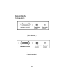
Appendix A
Connectors
SRP-250 Connector
( Serial Interface )
SRP-250P Connector
( Parallel Interface )
39
Interface Connector
Serial Interface
Pin No.
Signal name Direction
Function
1
FG
-
Frame Ground
2
TxD
Output
Transmit Data
3
RxD
Input
Receive Data
4
RTS
Output
Request To Send
6
DSR
Input
Data Set Ready
7
SG
-
Signal Ground
20
DTR
Output
Data Terminal Ready
Serial Interface Connection(Example)
Host(DTE ex 8251)
TXD
DSR
RXD
DTR
S.G
Printer
RXD
DTR
TXD
DSR
S.G
Parallel Interface Connector Pin Assignment
40
Pin No.
1
2
3
4
5
6
7
8
9
10
11
12
13
14
15
16
17
18
Signal Name
STB
DATA 1
DATA 2
DATA 3
DATA 4
DATA 5
DATA 6
DATA 7
DATA 8
ACK
BUSY
PE
SLCT
AUTO FEED
NC
SIGNAL GND
FRAME GND
NC
Pin No.
19
20
21
22
23
24
25
26
27
28
29
30
31
32
33
34
35
36
41
Signal Name
GND
"
"
"
"
"
"
"
"
"
"
"
INIT
FAULT
GND
NC
NC
SLCT
Drawer Connector
Pin No.
Signal name
Direction
1
Frame ground
-
2
Drawer kick-out drive signal 1
Output
3
Drawer open/close signal
Input
4
+24V
-
5
Drawer kick-out drive signal 2
Output
6
Signal ground
-
42
Appendix B
Specification
Printer
Ribbon
Paper
Adapter
Auto Cutter
ETC
Printing method
Number of head pin
Printing direction
Lines per second
Characters per line
Ribbon type
Color
Ribbon life
Paper type
Paper width
Roll diameter
Thickness
Overall dimensions
Weight
Types
Cutter type
Cutting width
Cutting thickness
Data buffer
Overall dimension
Weight
Rating
Power consumption
EMI
Safety standards
Reliability
Operation temperature
Operation humidity
Storage temperature
Storage humidity
Serial impact dot matrix
9 wires
Bi-directional
Approx. 3.5 LPS
40 (9*7), 32(9*9)
Cartridge type
Red & Black
Approx. Red (0.8 Million characters),
Black(1.5 Million characters)
Roll paper
W76mm ¡ ¾0.5mm (2.99” ¡ ¾0.22”)
Max. φ80mm (3.14”)
0.06mm ~ 0.085mm (0.002” ~ 0.003”)
115mm * 70mm * 58mm ( 4.53” * 2.77” * 2.29” )
1023gram ( 2.26lbs)
AD-1000A : U.S.A. ( 120 V / 60 Hz )
AD-1000B : Europe ( 230V/50Hz )
AD-1000C : UK ( 230V/50Hz)
AD-1000D : AUSTRALIA (230V/50Hz )
Gillotine type
Max. 85 mm
Max. 0.1mm
6k bytes
SRP-250A/AP, SRP-250C/CP:
177(W)*277(D)*141(H)mm(7.00”*10.9”*5.57”)
SRP-250B/BP:
177(W)*277(D)*186(H)mm(7.00”*10.9”*7.32”)
SRP-250D/DP:
177(W)*284(D)*183(H)mm(7.00”*11.2”*7.19”)
Weight(printer only) : Approx. 2.4kg (5.3lbs)
Weight(with box & accessories ) :
Approx. 4.5 kg (9.8lbs)
DC 27 V, 1.2 A
Standby : 16 W, Operation : 25 W
FCC class A, CE
UL/CSA, TUV,CE
MCBF : 5,000,000 lines (Except print head life )
Print head life : 150,000,000 Dots
0¡ É~ 40¡ É( 32¢ µ~ 104¢ µ)
30% ~ 80%
-10¡ É~ 50¡ É( 14¢ µ~ 122¢ µ)
10% ~ 95%
43
Appendix C
Removing Jammed Paper (A)
When the paper is jammed near the head carriage.
1) Open the front-cover and rear-cover.
2) Loosen the screw securing the head cover as shown the illustration.
CAUTION : The printer head becomes very hot during printing.
Allow it to be cool before you reach into the printer.
44
3)
4)
5)
6)
Remove the roll paper from the printer.
Remove the ribbon cassette.
Move the head carriage to the reverse direction of paper jammed by 1st gear
reduction as shown illustration.
Remove the jammed paper by rotating the paper-feed knob.
7) Replace the head cover and secure it with screw.
8) Replace the ribbon cassette and roll paper, then close the printer cover.
45
Removing Jammed Paper (B)
Paper is jammed when you insert the paper.
1) Open the front-cover and rear-cover.
2) Loosen the screw securing the guide-paper as shown the illustration.
CAUTION : The printer head becomes very hot during printing.
Allow it to be cool before you reach into the printer.
3)
4)
Remove the roll paper from the printer.
Remove the ribbon cassette.
46
5)
Remove the jammed paper by rotating the paper-feed knob.
6)
7)
Replace the head cover and secure it with screw.
Replace the ribbon cassette and roll paper, then close the printer cover.
47
CONTROL CODES
STAR mode
Control code
<ESC> "C" n
<ESC> "R" n
Hexadecimal code
1B 43 n
1B 52 n
<ESC> "M"
1B 4D
<ESC> "P"
<SO>
<SI>
<DC2>
<DC4>
1B 50
0E
0F
12
14
<ESC> "W" "1"
<ESC> "W" <1>
<ESC> "W" "0"
<ESC> "W" <0>
<ESC> "4"
<ESC> "5"
<ESC> "E"
<ESC> "F"
1B 57 31
1B 57 01
1B 57 30
1B 57 00
1B 34
1B 35
1B 45
1B 46
<ESC> "a" n
<ESC><BEL>n1 n2
1B 61 n
1B 07 n1 n2
<BEL>
07
<FS>
1C
<SUB>
1A
<EM>
19
<CAN>
<ESC> "@"
<ESC> "e" "0"
<ESC> "e" <0>
<DC3>
<DC4>
<ESC> U n
<ESC> - n
Control code
<ESC> "e" "1"
<ESC> "e" <1>
18
1B 40
1B 65 30
1B 65 00
13
14
1B 55 n
1B 2D n
Hexadecimal code
1B 65 31
1B 65 01
Function
Set page length at n lines
Select international character set.
Default is according to the dip switch
settings 3, 4 and 5.
Select 7 × 7(Half dots) character
size(Default setting)
Select 9×7(Half dots) character size
Select expanded character mode
Select inverted print mode
Cancel inverted print mode
Cancel expanded character
mode(Default setting)
Select expanded character mode
Cancel expanded character mode
(Default setting)
Red color print selection
Red color print deselection
Emphasized print mode selection
Emphasized print mode deselection
(Default setting)
Feed paper n lines
Adjust drive pulse width for peripheral
unit(Default setting)
Deferred drive command "A" for
peripheral unit 1
Immediate drive command "B" for
peripheral unit 1
Immediate drive command for
peripheral unit 2
Immediate drive command for
peripheral unit 2
Cancel print data in buffer
Initialize printer
FEED switch valid
(Default setting)
Set deselect mode
Set select mode
Set or Cancel uni-direction mode
Set or Cancel underline mode
Function
FEED switch invalid
<ESC> "z" "1"
<ESC> "z" <1>
<FF>
<ESC> d "0"
<ESC> d "1"
CITIZEN mode
Function code
<FF> "n"
<SO>
<SI>
<DC1>
<DC2>
<DC3>
<CAN>
<ESC> "P" "0"
<ESC> "P" "1"
<ESC> "-" "n"
<ESC> "1"
<ESC> "2"
<ESC> "C" "n"
<ESC> "f" "1"
<SUB>
<FS>
<ESC><BEL> n1 n2
<BEL>
<ESC> "U" "1"
<ESC> "U" <1>
<ESC> "@"
<ESC> "d" "0"
<ESC> "d" <0>
<ESC> "d" "1"
<ESC> "d" <1>
<ESC> "W" "1"
<ESC> "W" <1>
<ESC> "y" n
1B 7A 31
1B 7A 01
0C
1B 64 30
1B 64 31
Set 1/6 inch line feed
Hexadecimal code
0C + n
0E
0F
11
12
13
18
1B, 50, 00
1B, 50, 01
1B, 2D, n
1B, 31
1B, 32
1B, 43, n
1B, 66, 01
1A
1C
1B, 07, n1, n2
Function
"n" -lines paper feed command
Enlarged character command
Normal character command
Initial set command
Inverted character command
Red color print command
Clear command
Paper full cut command
Paper partial cut command
Underline command
1/9 inch paper feed preset command
2/9 inch paper feed preset command
Page length set command
Form feed command
Second drawer drive command
First drawer quick drive command
Drive pulse setting command for the
first drawer
First drawer drive command
Select uni-directional print mode on/off
07
1B 55 31
1B 55 01
1B 40
1B 64 30
1B 64 01
1B 64 31
1B 64 01
1B 57 31
1B 57 01
1B 79 n
Page feed (form feed)
Full cut
Partial cut
Initialize printer
Trigger auto-cutter drive (full cut)
Trigger auto-cutter drive (partial cut)
Select expanded character mode on/off
Set n/144 inch line feed