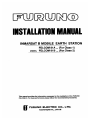
1
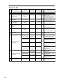
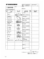
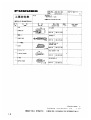
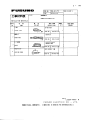
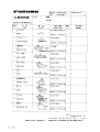
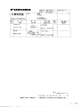
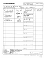
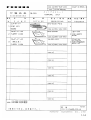
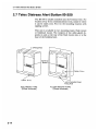
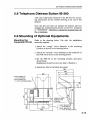
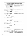
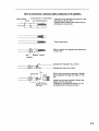
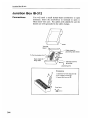
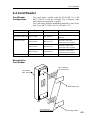
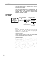
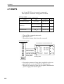
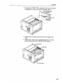
C
Yo u r L o c a l A g e n t / D e a l e r
9-52, Ashihara-cho,
Nishinomiya, Japan
Te l e p h o n e :
Te l e f a x :
0 7 9 8 - 6 5 - 2 111
0798-65-4200
All rights reserved.
Printed in Japan
PUB. No. IME-56090-N
(TENI)
FELCOM 81A/B
FIRST
EDITION
N
:
:
N O V. 1 9 9 6
S E P. 5 , 2 0 0 0
Table of Contents
SAFETY INSTRUCTIONS
i
1. System Configuration and Equipment Lists
1-1
2. Mounting of Units
2-1
2.1 Antenna Unit・・・・・・・・・・・・・・・・・・・・・・・・・・・・・・・・・・・・・・・・・・・・・・・・・2-1
2.2 Communication Unit ・・・・・・・・・・・・・・・・・・・・・・・・・・・・・・・・・・・・・・・2-9
2.3 Telephone・・・・・・・・・・・・・・・・・・・・・・・・・・・・・・・・・・・・・・・・・・・・・・・・・・・2-11
2.4 Terminal Unit (for class 1 only)・・・・・・・・・・・・・・・・・・・・・・・・2-12
2.5 Printer ・・・・・・・・・・・・・・・・・・・・・・・・・・・・・・・・・・・・・・・・・・・・・・・・・・・・・・・2-12
2.6 Junction Box IB-312 ・・・・・・・・・・・・・・・・・・・・・・・・・・・・・・・・・・・・・ 2-13
2.7 Telex Distress Alert Button IB-350・・・・・・・・・・・・・・・・・・・・2-14
2.8 Telephone Distress Button IB-360 ・・・・・・・・・・・・・・・・・・・・・2-15
2.9 Mounting of Optional Equipments・・・・・・・・・・・・・・・・・・・・・2-15
2.10 Checking the Installation ・・・・・・・・・・・・・・・・・・・・・・・・・・・・・・・2-17
3. Wiring of Standard Equipment
3-1
4. Connection of Optional Equipment
4-1
4.1 Facsimile PFX-50・・・・・・・・・・・・・・・・・・・・・・・・・・・・・・・・・・・・・・・・・・・4-1
4.2 Received Call Unit IC-301・・・・・・・・・・・・・・・・・・・・・・・・・・・・・・・・4-1
4.3 AC/DC Power Supply Unit PR-300・・・・・・・・・・・・・・・・・・・・・ 4-1
4.4 Card Reader・・・・・・・・・・・・・・・・・・・・・・・・・・・・・・・・・・・・・・・・・・・・・・・・・・4-3
4.5 DGPS・・・・・・・・・・・・・・・・・・・・・・・・・・・・・・・・・・・・・・・・・・・・・・・・・・・・・・・・・ 4-6
5. Initial Settings
5-1
5.1 Hatch Direction and Heading Adjustment・・・・・・・・・・・・・・5-1
5.2 Setting of Telephone ・・・・・・・・・・・・・・・・・・・・・・・・・・・・・・・・・・・・・・・5-2
5.3 Setting for Antenna Cable Length・・・・・・・・・・・・・・・・・・・・・・・ 5-3
5.4 Attaching the Compass Safe Distance and
Inmarsat B Seals ・・・・・・・・・・・・・・・・・・・・・・・・・・・・・・・・・・・・・・・・・・・・5-4
5.5 Facsimile PFX-50 Setting・・・・・・・・・・・・・・・・・・・・・・・・・・・・・・・・・5-5
5.6 Personal Computer Connection ・・・・・・・・・・・・・・・・・・・・・・・・・・ 5-6
6. System Setup
6-1
6.1 Setting Up ・・・・・・・・・・・・・・・・・・・・・・・・・・・・・・・・・・・・・・・・・・・・・・・・・・・ 6-1
6.2 Registering Answerback Code (Class 1 only) ・・・・・・・・・6-2
Outline Drawings・・・・・・・・・・・・・・・・・・・・・・・・・・・・・・・・・・・・・・・・・・・・・・・・・・・・D-1
Interconnection Diagrams・・・・・・・・・・・・・・・・・・・・・・・・・・・・・・・・・・・・・・S-1
Schematic Diagrams・・・・・・・・・・・・・・・・・・・・・・・・・・・・・・・・・・・・・・・・・・・・・・ S-2
Facsimile PFX-50
Received Call Unit IC-301
(Max. 3)
100VAC
100VAC
Facsimile PFX-50
Telephone FC755D1
Telephone FC755D1
Telephone FC755D1
Card Reader MCT-1540-55
PC
MJ-2S
MJ-2S
MJ-2S
MJ-2S
Rosette
MJ-2S
DGPS
Junction Box (1)
IB-312
(class 1 only)
Terminal
Unit
IB-581
Printer
PP-510
Navaid
AD-100
24V DC
24V DC
24V DC
100/220V AC
* : CIF & NMEA are available.
(No necessary to change any setting.)
Telephone Distress
Button
IB-360
Telex Distress Button
IB-350
(class 1 only)
(class 2 only)
AC/ DC Power
Supply Unit
PR-300
*
Optional Supply
Standard Supply
MJ-2S
MJ-2S
MJ-2S
MJ-2S
Rosette
MJ-2S
Telephone
FC755D1
Communication
Unit
IB-281
Antenna
Unit
IB-181
1. System Configuration and
Equipment Lists
1-1
Complete Set
No
Name
Type
Code No.
Mass (kg)
Qty
1
Antenna Unit
IB-181
---
95
1
2
Communication Unit
IB-281
---
15
1
3
Terminal Unit
IB-581
---
6
1
Class 1 only
w/Installation Materials
CP16-01140 (page 1-8)
4
Telephone
FC755D1
---
1.0
1
w/Installation Materials
CP16-00511(page 1-11)
5
Junction Box
IB-312
---
1.2
11
w/Installation Materials
CP16-01102 (page1-9)
IB-350
---
0.5
1
Class 1 only
w/Installation Materials
CP16-00700 (page 1-12)
IB-360
---
0.5
1
w/Installation Materials
CP16-00700 (page 1-12)
SP16-01000
004-441-460
CP16-01300
000-043-215
No antenna cable
w/Installation Materials
CP16-01101
CP16-01310
000-043-216
Antenna cable 30m
w/Installation Materials
CP16-01101
6
7
8
9
Telex Distress Alert
Button
Telephone Distress
Button
Spare Parts
10
1 set (page 1-16)
Installation Materials
(Selection)
1 set
000-043-217
Antenna cable 50m
w/Installation Materials
CP16-01101
CP16-01330
000-043-218
Antenna cable 100m
w/Installation Materials
CP16-01101
CP16-01111
004-441-420
For 8D cable
(page 1-6)
CP16-01121
004-441-430
CP16-01131
004-441-770
AD-100
---
CP16-01320
Installation Materials
(Selection)
11 AD Converter
1-2
Remarks
1 set
For 12D cable
(page 1-7)
No antenna cable
(page 1-7a)
1.5
1
Gyro Interface Optional Equipment
No
Name
Type
Code No.
Mass (kg)
Remarks
1
Facsimile
PFX-50
---
8.0
w/Inst. Materials
CP16-00590 (page 1-13)
2
Received Call Unit
IC-301
---
0.5
w/Inst. Materials
CP16-00700 (page 1-12)
3
Telephone
FC755D1
---
1.0
w/Inst. Materials
4
Modular Jack Box
OP16-10
000-043-278
0.2
5
Modular Jack Box
OP16-11
000-043-279
0.1
6
Modular Jack Box
OP16-13
000-043-228
0.1
7
AC/DC Power
Supply Unit
PR-300
---
14.5
For 100-230 V
8
Card Reader
MCT-1540-55
000-043-333
0.17
main body only
MCT-1540-81
000-043-335
with Inst. Material
9
5-pair cable 10m
CO-SPEVV-SB-C
0.2 × 5P
000-560-452
For junction box
10 5-pair cable 20m
000-103-868
11 5-pair cable 30m
000-103-869
12 5-pair cable 40m
000-132-829
13 5-pair cable 50m
000-132-828
14 1-pair cable 10m
15 1-pair cable 20m
CO-SPEVV-SB-C
0.2 × 1P
For junction box
000-110-681
000-138-789
16 1-pair cable 30m
000-138-790
17 1-pair cable 40m
000-138-791
18 1-pair cable 50m
000-138-792
19 Printer
PP-510
20 Ribbon Cartridge
SP-16051NB
000-133-029
For Printer
A2 1PLY W
000-134-903
12 total
A2 2PLY WW
000-134-780
12 total
K52 257 × 50M25TRU
000-806-564
12 total, B4 size
K52 216 × 50M25TRU
000-806-565
12 total, A4 size
23 Lifting Metal
OP16-15
004-442-460
Gyro Interface
24 Antenna Cover
QB05-1801-0
100-079-480
21 Printer Paper
22 Recordings Paper
25 Installation Materials OP16-01602
26 Transformer
27
Vibration Converter
Kit
28 HSD I/F
---
3.6
For FELCOM 81 B
For DGPS + HSD Modem
004-442-900
1
220VAC ⇒ 100VAC
FIT-100
000-139-903
OP16-22
004-438-700
KLASHOPPER
PCMCIA1400
000-142-952
For laptop computer
KLASHOPPER PCI-400
000-142-951
For desktop computer
1-3
2.3 Telephone
2.3 Telephone
General
The telephone can be installed on a tabletop or a bulkhead.
Select a location where the unit can easily be operated.
For installation on a wooden table, use the mounting
base and tapping screws (supplied).
For installation on a steel table, fix the telephone with
nuts and bolts.
For bulkhead mounting, use the bulkhead mounting
base (supplied with telephone accessories).
Mounting location
Select a location where temperature and humidity are
moderate and stable. Secure sufficient space around the
unit for ease of operation and maintenance.
Mounting
The mounting dimensions are given in the outline drawing
at the end of this manual. Determine the mounting location, leaving sufficient space around the unit, and then fix
the mounting base to the mounting location. The mounting
base is different for bulkhead and tabletop mounting,
however the mounting procedure is the same for all.
Mounting Base
Table top: Use installation
materials.
Bulkhead: Use telephone
accessories.
Secure
mounting
base with
tapping
screws.
Attach
handset
supporter
here.
Unfasten
this
screw.
1. Fix the mounting base to the mounting location with
four tapping screws (4 × 16).
2. On the underside of the telephone, unfasten the screw
shown in the figure at left. (The screw may be discarded.) Attach double-sided tape (supplied) to the handset
supporter. Fasten the handset supporter to the underside
of the telephone with a screw (supplied : 3 × 14).
3. The catch in the receiver cradle functions to hang up the
handset completely. Set the catch in the upward position
as shown below. (To detach the handset from the
hanger, slide the handset upward.)
Bottom View
Mounting Base Stopper
To remove the telephone from mounting
base, press the mounting base stopper,
and slide telephone forward.
Handset Supporter
Catch
4. Set the telephone to the four catches in the mounting
base and then slide it toward you until you hear a click.
5. Attach the "SLIDE" label (supplied) to the handset.
6. Attach English language label (supplied) to the telephone.
2-11
2.10 Checking the Installation
2.10 Checking the Installation
General
Before turning on the system, check for proper installation,
following the procedure shown below.
Standard Equipment
Communication
unit
Are all connectors firmly fastened?
Is the copper strap firmly fastened?
Junction boxes
IB-312
Are all connections on the terminal board correctly made?
Are all cables properly grounded by cable clamp?
Is the unit properly grounded?
Telex Distress
Alert
Button/Telephone
Distress Button
Are all connections on the terminal board correctly made?
Antenna unit
Is the unit properly grounded?
Printer
Is the unit firmly fastened by mounting fixtures?
Telephone
Is the mounting base firmly fastened?
Is the unit firmly fastened to the mounting location (bulkhead, tabletop)?
Optional Equipment
Facsimile
Is the unit firmly fastened?
Received call unit
Are all connections on the terminal board correctly made?
A-D Converter
AD-100 NAV. Data
Are all connections on the terminal board correctly made?
2-17
4.3 AC/DC Power Supply Unit PR-300
Changing the
power fuse
AC power
sourse switch
Change the power fuse according to input voltage as
follows.
Input
Output
100/110 VAC
10 A
200/220 VAC
5A
100V 10A
220V 5A
20A
ON
ON
OFF
AC IN
OFF
DC IN
FURUNO
PR-300
Fuse for ship's mains
DC power sourse
switch
DC OUT
Figure 8 AC-DC power supply unit PR-300, rear view
Ground
4-2
Connect a ground wire between ship's superstructure and a
ficing screw on the PR-300.
4.4 Card Reader
4.4 Card Reader
Card Reader
Configuration
The card reader useable with the FELCOM 81 is the
MCT-1540-81 (Code No. 000-043-335). Extension cable
and modem are optionally available.
The card reader without installation materials is also available (Type MCT-1540, Code No. 000-043-333).
Name
Main Unit
Type
Code no.
MCT-1540
000-043-332
004-435-030
Cable, Connector, Velcro
fastener
CP16-01010
004-434-970
No armor 50m cable
with connectors (option)
CP16-01020
004-434-980
No armor 100m cable
with connectors (option)
CP16-01030
004-434-990
No armor 150m cable
with connectors (option)
CP16-01040
004-435-000
option
Installation Materials CP16-01400
Extension Cable
Modem
Remarks
Mounting the
Card Reader
Velcro fasteners
for Card Reader
Card Reader
MCT-1540-55
To Mounting Surface
170g
Velcro fasteners
for mounting surface
To Mounting Surface
4-3
4.4 Card Reader
・ The card reader should be installed nearest the most
frequently used telephone.
・ The card reader connects to the communications unit
(IB-281) of the FELCOM 81 with two connection cables
(supplied) whose total length is 6.5 meters. Longer
lengths are optionally available.
Connection of
Card Reader
Connection cable ②
Connection cable ①
FELCOM81
IB-281
Communication
Unit
Card Reader
Converter Connector
AC adaptor
・ Power
Power the card reader with 100 VAC power. An AC
adaptor comes with the card reader for plugging the
equipment in an electrical outlet.
・ Connection cable 1
Connect the 8-pin connector to the card reader and the
25-pin connector to the converter connector.
・ Connection cable 2
Connect one end of the cable (type 16S0214, 5 m) to the
CARD READER connector on the communications unit
and the other end to the converter connector.
If the standard connection cables are not long enough,
longer cables are optionally available, or use the internal
modem (option). Install longer cable when the distance to
the communications unit is between 5 and 150 meters and
use the modem when the distance is between 150 and
1000 meters. See page S-2a for details.
4-4
4.4 Card Reader
Setting up Telephones/Facsimiles
Set up telephones and facsimiles according to call application desired.
Application
1. Non-credit card call only:
Only non-credit card call
can be made; credit card
call cannot be made.
2. Credit card call/non-credit card call:
Both credit card and noncredit card calls can be
made.
3. Credit card call:
Only credit card can be
used to make call.
Preset
1. Pick up receiver of No.1 telephone.
2. Dial setting desired.
No.1 telephone cannot be set for credit card only call.
Beep sounds for correct setting. Busy signal is emitted
for error.
*94
P1
P2
Code number
P1
0: All terminals
1: No.1 Telephone
2: No.2 Telephone
3: No.3 Telephone
4: No.4 Telephone
5: No.5 Telephone
6: No.6 Telephone
#
End code
P2
0: Non-credit card call only
1: Credit card call/non-credit
card call.
(This is the default setting.)
2: Credit card call/non-credit
card call
3: Credit card call only
4: Credit card call only
3. Hang up the receiver.
4-5
4.5 DGPS
4.5 DGPS
An L-band DGPS receiver may be connected.
This requires a connector fixing plate for DGPS.
CP16-01602 (Code No.: 004-442-900)
Name
Connector fixng plate
Type
Code No.
Qty
CP16-01606
004-442-910
1
PH5P-L200-SMP2P
000-141-558
1
PH2P-L300-SMR2P
000-141-559
1
M4 × 8
000-881-445
4
Cable assy
Pan head screw
1. Turn off the communication unit.
2. Detach the cover.
3. Detach the dummy plate from the rear panel.
Connector fixing plate
Rear panel of communication unit
Detach dummy
plate and fasten
connector fixing
plate with screws
used to fasten
dummy plate.
Dummy plate
4. Fasten the connector fixing plate (supplied) to the rear
panel with the screws used to fix the dummy plate.
5. Detach all connectors from the rear panel; dismount the
power supply unit and the panel.
4-6
5.2 Setting of Telephone
5.2 Setting of Telephone
Change dialing format from dial to pushbutton as follows.
(The handset should be hung in the hanger.)
FC622SLIWG
FC755D1
1. Press the
STO
key.
2. Press the
#
key.
3. Press the
*
key to display "Pb."
4. Press the
STO
key again.
1. Insert tip of a mechanical pencid under plastic cover
to remove cover, and then remove memo paper.
2. Use the tip of the mechanical pencil to set DIP Switch.
VOLUME
DIAL
PB
BELL OFF
S
ON
: Default
Setting
OFF
DP
L
DIAL : Selects dialing format; dial pulse (20PPS) or
push button. Select push button (PB).
3. Restore memo paper and plastic cover.
5-2
5.4 Attaching the Compass Safe Distance and Inmarsat B Seals
5.4 Attaching the Compass Safe Distance and
Inmarsat B Seals
Attach the compass safe distance seals (supplied with
installation materials) for the units shown below.
When the same units (for example: telephone, facsimile,
etc.) are used for other than FELCOM 81, attach ""seals b
to them to distinguish.
5-4
5.5 Facsimile PFX-50 Setting
5.5 Facsimile PFX-50 Setting
Turn on the power while dialing [*], [1], [3] to initialize
the PFX-50's memory. Change the dial mode to "push
button" with the MODE switch. (Choose position "T". )
Dial Mode
MODE Switch
Chosse "T".
5-5
5.6 Personal Computer Connection
5.6 Personal Computer Connection
You can use a personal computer as the terminal unit for
the FELCOM81, by installing the contents of a program
disk on the PC.
Note: Basic knowledge of DOS commands is required.
16-501-091
Requirement; Type :
Code No: 004-441-520
Booting up by
disk drive
1. Format a floppy disk (command "format / s " ).
Refer to PC operator's manual about formatting.
2. Copy the following three files from program disk to
formatted floppy disk :
B TERM.EXE
CONFIG.SYS
AUTOEXEC.BAT
3. Rewrite "AUTO EXEC .BAT" file.
b term / tb : \ telex / r → b term
Delete portion underlined above.
Turn off the power. Turn on the power. Confirm that the
software boots up by disk drive properly.
Booting up by
hard disk drive
1. Make the directory "F81" on the hard disk (drive C).
Refer to PC manual about how to make a directory.
2. Copy "B TERM. EXE"of program disk to "F81"
directory.
3. Turn off the power. Turn on the power.
Execute "b term" in the "F81" directory.
Note: You need about 500 kB of RAM to boot the
program. Therefere, when booting up by hard disk,
minimize the contents of "CONFIG.SYS " file.
5-6
6. System Setup
6.1 Setting Up
Overview
Set up the terminal unit, editor screen and communication
unit (Class 2).
When there is no navigation input or gyro input, enter
them manually referring to operator's manual.
Turn on the Main Unit and Terminal Unit. After a while,
the Main Menu, shown below, appears.
File Edit Telex Setup
BRK
(Nov-10-96 16:25)
Date
Standby Display
Setting up
Key Operation
1. Terminal Unit ・・・・・・・・・・・・・・・・・・
Entry of date,
answerback code, etc.
F4
⇒
3
See next page.
2. Editor Screen ・・・・・・・・・・・・・・・・・・
Line numbering ON/OFF,
Selection of cursor type, etc.)
F4
⇒
4
3. Communication Unit ・・・・・・・・・・・・
Selection of ocean region,
Telephone/Fax setting, etc.)
F4
⇒
6
6-1
6.2 Registering Answerback Code (Class 1 only)
6.2 Registering Answerback Code (Class 1 only)
Overview
Enter ship's answerback code at installation.
The answerback code cannot be changed once
registered. Confirm the code before pressing
the Enter key.
Procedure
Press F4 ,
display.
Cursor
3
and
in this order at standby-
8
!! ATTENTION: CAN NOT REENTER !!
Enter your ship's answerback code given by
Inmarsat, then press the Enter key.
[Normally, answerback code consists of telex IMN
(IMN: Inmarsat Mobile Number) given by Inmarsat
and four characters requested by applicant.]
How to enter
Telex IMN No.
(9 digits)
(Ex.) 343164830
6-2
4 characters
JFKS
X