1
&KDSWHU%
+DUGZDUH
,QVWDOODWLRQ
&KDSWHU%+DUGZDUH,QVWDOODWLRQ
%+DUGZDUH,QVWDOODWLRQ
%%HIRUH,QVWDOODWLRQ
The ICP Controller is designed for minimum power consumption and maximum operational
security. It therefore contains delicate electrical components (CMOS). In order to avoid
damages caused by electrostatic charges, the following warning must be observed during
installation:
Never take the ICP Controller out of the anti-static bag unless this is done at an antistatic work place and the person handling the ICP Controller is secured against electrostatic charge through wrist bands. If these instructions are not observed, the user
risks damage or destruction of the CMOS components of the ICP Controller !
%7RROV
Before installing, please switch off the complete computer system and remove all cables
including the power cable. Open the case of the host computer with an appropriate screwdriver (usually a medium sized Philips screwdriver).
%,QVWDOOLQJWKH&DFKH5$06,00
,WLVQRWSRVVLEOHWRRSHUDWHWKH,&3&RQWUROOHUZLWKRXW&DFKH5$0
7KH,&3&RQWUROOHULVGHOLYHUHGZLWKRXW5$00%
If the ICP Controller is not yet equipped with cache RAM, or if another SIMM is to be installed, we recommend adding it before you install the ICP Controller in your computer system. As mentioned before, the ICP Controller can be run with different cache RAM sizes.
The minimum cache RAM size is 4MB. The maximum cache RAM size is 64MB. The ICP
Controller provides one socket for a standard 72 PIN SIMM (Single Inline Memory Module).
The SIMM can either have parity (=36 Bit), or non-parity (=32 Bit). The ICP Controller's
memory controller can use a Fast Page Mode (FPM) SIMM with 60ns (or less) or an Extended Data Out (EDO) SIMM with 50ns. The use of an EDO SIMM increases the performance of the ICP Controller. The SIMM is correctly plugged into the SIMM socket if it is
engaged correctly into the socket's metal hooks and if all contacts of the SIMM are equally
contacting the corresponding pins of the socket.
Automatic Cache RAM Recognition
Each time you switch on the computer system, the ICP Controller automatically recognizes
how much cache RAM is available and configures itself accordingly.
&KDSWHU%*'78VHU
V0DQXDO
Recommended SIMM Manufacturers
SIMMs from Goldstar, Motorola, NEC, Samsung, Siemens, Texas Instruments, and Toshiba
have been successfully tested with the ICP Controllers. This recommendation does not imply an evaluation of quality. SIMMs from other manufacturers may be equally suitable. You
can use single- and double-sided SIMMs. When using double-sided SIMMs with high power
consumption special care should be taken that both, the ICP Controller and SIMM are
properly cooled.
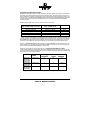
SIMM sizes and types which can be used on the ICP Controller :
Fast Page Mode (FPM) SIMM,
60ns (or less), Jumper S1 not set
1M*32 and 1M*36
2M*32 and 2M*36
4M*32 and 4M*36
8M*32 and 8M*36
16M*32 and 16M*36
Extended Data Out (EDO) SIMM,
(*)
50ns , Jumper S1 set
1M*32 and 1M*36
2M*32 and 2M*36
4M*32 and 4M*36
8M*32 and 8M*36
16M*32 and 16M*36
RAM Size
4MB
8MB
16MB
32MB
64MB
(*)
When using an EDO SIMM on the ICP Controller, jumper S1 has to be set (see next page).
For the operation of a Fast Page Mode SIMM S1 must remain open. We have tested several
EDO SIMMs with 60ns without any problems, but according to the specification of the ICP
Controller's Intel i960 CPU, 50ns are necessary to comply with the timing requirements.
There is a 16MB SIMM available which allows an online DRAM Error Correction (ECC). For
further details on this SIMM and the 50ns EDO SIMMs, contact your ICP vortex representative or check our Website (http://www.icp-vortex.com).
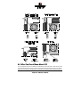
Obviously, the question arising at this point is: "How much cache RAM do I need ?"
In the following table, we made RAM equipment suggestions for the minimum, typical and
optimum RAM size (Note: Naturally, all ICP Controllers work flawless with the smallest RAM
size stated in column 2 of this table).
Controller Usable Sizes
in [MB]
GDT6111RP
GDT6121RP
GDT6117RP
GDT6127RP
GDT6511RP
GDT6521RP
GDT6517RP
GDT6527RP
GDT6537RP
GDT6557RP
Suggested RAM equipment
Minimum
Typical
Optimum
4,8,16,32,64
4
8
16
4,8,16,32,64
4
8
16,32
4,8,16,32,64
8
16
32
&KDSWHU%+DUGZDUH,QVWDOODWLRQ
%:KDW<RX6KRXOG.QRZ$ERXW6&6,
It is very important for you to observe the information and notes given in this section of the
User’s Manual because it helps to ensure that the SCSI devices that are used in connection
with the ICP Controllers are operated in a successful, long-lasting and trouble-free manner.
&KDSWHU%*'78VHU
V0DQXDO
In many cases, this information is not only applicable to ICP Controllers, but in general to
all those SCSI systems which, like the ICP Controllers, use Single Ended SCSI bus channels.
According to its definition, the SCSI bus provides access to several participants that are
physically connected through an appropriate SCSI bus cable. To achieve a sufficiently good
signal quality, it is not only recommended to use very good cables and connectors, but also
to terminate both ends of the cable properly. For an unambiguous identification on the bus,
all participants have a unique number – the so-called SCSI-ID. Further details on these
topics can be found on the following pages.
Please note that 98% of all SCSI-related problems are caused by bad SCSI cables,
wrong SCSI bus termination and duplicate SCSI-IDs.
Recently, strong efforts have been made to automate the setting of the SCSI bus termination and SCSI-ID on the SCSI bus. An appendix to the SCSI-3 specification with the title
SCAM (SCSI Configured AutoMatically) has been created. It includes a description of all the
functions necessary for building a SCAM compatible SCSI device or controller. Unfortunately, in real life SCAM is rather a definition than a useful help. Even worse, SCAM has
added other problems and more confusion to the already difficult SCSI topic. As long as it
is possible to buy and operate SCSI devices without the SCAM feature (99.9% of all currently available devices do not support SCAM), massive problems are very likely to occur.
Therefore, the ICP Controllers only rely on the well proven and standard method of setting
SCSI-IDs and SCSI bus terminations and do not expect any further capabilities of the SCSI
devices.
%
66&6,
,&&DEOHV
The quality and overall length of the cable, as well as the number and quality of the SCSI
connectors is very important for both internal and external SCSI cables. Generally, internal
SCSI cables are 50 or 68 conductor flat ribbon cables. To connect external SCSI devices,
round and shielded cables with appropriate connectors are typically used. The minimum
cross section per line has been defined in the SCSI-3 specification as follows:
50 conductor cables: minimum 28 AWG conductors
68 conductor cables: minimum 30 AWG conductors.
and with
The typical impedance of a SCSI cable is 84 Ohm +/- 12 Ohms. The maximum difference in
impedance between two conductors of a SCSI cable must not exceed 12 Ohms. External
round cables should have a SCSI-compliant placement of the inside conductors. Besides
the cables, the right connectors for a cable are also very important. It is highly recommend
to use highest quality connectors, only. The following table shows the maximum cable
lengths allowed for a given transfer rate. Based on many years of SCSI experience, the
lengths we recommend are in some cases shorter than theoretically possible. The information in the table refers to one SCSI channel and represent the overall length of the cable,
including internal and external parts.
SCSI Bus Width
SCSI Mode
8 Bit, narrow
8 Bit, narrow
16 Bit, narrow
16 Bit, wide
16 Bit, wide
Fast
Fast-20, Ultra
Fast
Fast
Fast-20, Ultra
Synchronous Data
transfer Rate
10 MB/sec.
20 MB/sec.
10 MB/sec.
20 MB/sec.
40 MB/sec.
Number of
Participants
8
4
8
8
4
&KDSWHU%+DUGZDUH,QVWDOODWLRQ
Maximum
Length
2.0 m
1.5 m
2.0 m
2.0 m
1.5 m
With regard to Fast-20 devices, the maximum number of participants and the maximum cable length have to be strictly observed when a Fast-20 device (even if it is only one) is running in Fast-20 mode. In each case , the minimum cable length is 0.5 m. In addition to
specifications mentioned above, the following should be kept in mind when selecting and
installing SCSI cables:
Always install SCSI cables that are as short as possible. The lengths in the table above
are absolute maximum lengths. (Total length of internal and external cables per channel).
Avoid using SCSI cables with more connectors than actually needed. Never select a SCSI
mode or operate a SCSI device with a cable that is not appropriate for this mode.
The minimum distance between two connectors of a SCSI cable is 20 cm.
Avoid cable stubs. If this is not possible, keep the stub length below 10 cm.
“Star cablings” are not allowed.
Keep the number of transitions from flat to round cables and vice versa as small as possible. It is usually best is to use flat or round cables, only.
Check these points when routing SCSI cables:
- Avoid kinks in the SCSI cable
- Do not roll the SCSI cable up on itself
- Avoid routing the cable next to other cables
- Avoid routing the cable in the vicinity of noise sources such as power supplies
- Avoid routing the cable over sharp edges and in areas where it could get caught up
- Avoid routing/sticking the cable directly onto metal surfaces
Below is a list of some manufacturers of high quality SCSI connectors and cables: 3M, AMP,
Amphenol, Fujitsu, Harting, Honda, Methode, Molex, Robinson Nugent, Yamaichi.
When making home-made SCSI cables, make sure that the insulation displacement connectors are properly aligned and firmly pressed into the flat ribbon cable. Otherwise, the whole
cable might turn out to be a big short-circuit. Furthermore, check carefully that PIN 1 of the
cable connects to PIN 1 of the connectors. A simple short-circuit and continuity test before
running the devices helps you to save time and money.
The same warnings as for home-made cables apply when you buy non-brand cables. If you
plan to run Fast-20 devices, you should explicitly ask your dealer if these cables are appropriate for the Fast-20 mode. (Note: The ICP product range also includes some high quality
SCSI accessories. Along with external SCSI brackets, there is a special FAST-20 Wide SCSI
cable. Please see section B.4.4 of this User's Manual or check our Website: http://www.icpvortex.com, for further details).
&KDSWHU%*'78VHU
V0DQXDO
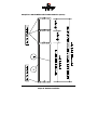
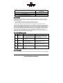
([DPSOHIRUD6&6,)ODW5LEERQ&DEOHIRU%LW6&6,'HYLFHVQDUURZ
&KDSWHU%+DUGZDUH,QVWDOODWLRQ
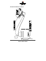
([DPSOHIRUD6&6,)ODW5LEERQ&DEOHIRU%LW6&6,'HYLFHVZLGH
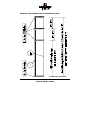
&KDSWHU%*'78VHU
V0DQXDO
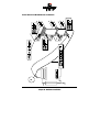
([DPSOHIRUD6&6,5RXQG&DEOHIRU%LW6&6,'HYLFHVZLGH
&KDSWHU%+DUGZDUH,QVWDOODWLRQ
%
66&6,
,77HUPLQDWLRQ
In order to ensure a flawless and interference-free signal transmission on the SCSI bus and
to minimize the detrimental effects of external noise generators, both ends of the SCSI cable have to be terminated. The SCSI specification prescribes two alternative termination
modes for Single-Ended SCSI bus systems: the passive termination and the active termination, also known as Alternative-2 termination. The passive termination consists of a 220
Ohm pull-up and a 330 Ohm pull-down resistor for each signal. Today, the passive termination is mostly used in systems with synchronous data transfer rates not exceeding 5 MB/sec,
which is rather slow. The active termination circuit consists of a 110 Ohm precision-resistor
per signal and a common 2.85Volt voltage regulator. Thus, all signals are actively pulled up
to a certain level. The active termination provides much better signal quality and significantly reduced liability to noise. All ICP Controllers are equipped with an active SCSI bus
termination. The voltage for the termination circuitry (passive and active) is supplied either
by the SCSI device itself, or by the TERMPWR line of the SCSI bus. Every SCSI device, regardless of whether it is a hard disk, a printer, or a ICP Controller, must have a SCSI bus
termination. In addition, it must be possible to enable and disable the SCSI bus termination (on some devices, resistor array packs or a jumper have to be removed, on others, like
the ICP Controllers, soft-switches allow a very comfortable setting of the SCSI bus termination). Furthermore, on each SCSI device it must be possible (for example through a jumper)
to switch the voltage on the terminator power line (TERMPWR) of the SCSI cable on or off.
For all configurations with ICP Controllers, we recommend that you use exclusively SCSI
devices with an active SCSI bus termination:
Always use active SCSI bus termination.
Do not use SCSI devices with passive SCSI bus termination (e.g., CD-ROMs) for the termination of the SCSI cable.
Always terminate only the two ends of a SCSI cable.
The TERMPWR jumpers on the ICP Controller PCB (per channel, one) should always be set.
In this way, it is the ICP Controller which supplies the termination power on the SCSI cable
and no other SCSI device may supply termination power on the cable.
With regard to a proper termination in SCSI configurations comprising of ICP Controllers,
SCSI devices, and SCSI cables, it is appropriate to go into further detail.
This already difficult topic is further complicated by the fact that for each SCSI channel, the
1, 2, and 3 channel Wide SCSI or Wide & Ultra SCGDTICP Controllers have a dual connector
system. ICP provides both a standard 50 pin header and a 68 pin receptacle. This is an
enormous advantage of ICP products; firstly, because you do not have to spend your money
on expensive adapters, second, because it offers you more connections. To make things
even more sophisticated, there is an external 68 pin connector for channel A (in fact, there
are three connectors for channel A on the controller !). The only secure way of finding out
which particular connector to use and which terminator to enable is by analyzing the table
below.
Note: To enable the option Auto (available for channel A only), or toggle between the ON
and OFF termination settings for a ICP Controller SCSI channel, use the Configure Controller
menu in GDTSETUP.
The connections listed in the table below are the only valid connections allowed. Any other
connection setup, even if physically possible, is not allowed as it will cause serious malfunctions or even the destruction of the SCSI devices and/or the ICP Controller.
&KDSWHU%*'78VHU
V0DQXDO
GDT6111RP, GDT6121RP, GDT6511RP, GDT6521RP
Valid connections and required GDTSETUP settings for channel A
External female
connector, 50 pin
Internal male connector channel A,
50 pin
Occupied and end terminated
Not occupied
Occupied and end terminated
Occupied and end terminated
Not occupied
Occupied and end terminated
Not occupied
Occupied and both ends terminated, i.e.,
channel A connector is located between
the two ends.
Not occupied
Not occupied
Channel A
termination
On or Auto
Off or Auto
On or Auto
Off
On or Auto
Valid connections and required GDTSETUP settings for channel B (not channel A)
Internal female connectors channel B, 50 pin
Channel B termination
Occupied and end terminated
Not occupied
Occupied and both ends terminated, i.e., channel B connector is
located between both ends
On
On
Off
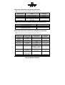
GDT6117RP, GDT6127RP, GDT6517RP, GDT6527RP, GDT6537RP
Valid connections and required GDTSETUP settings for channel A
External female
connector, 68 pin
Internal female
connector, 68 pin
Internal male connector
channel A, 50 pin
Channel A
termination
Occupied and end
terminated
Occupied and end
terminated
Occupied and end
terminated
Not occupied
Occupied and end terminated
Not occupied
Not occupied
Off or Auto
Not occupied
On or Auto
Not occupied
Occupied and end terminated
Occupied and end terminated
Occupied and end terminated
Occupied and both ends
terminated, i.e., channel A
connector is located between the two ends.
Not occupied
Off or Auto
Not occupied
Off
Not occupied
On or Auto
Not occupied
Occupied and end terminated
Not occupied
Not occupied
Not occupied
Not occupied
Occupied and end terminated
Occupied and both ends
terminated. Channel A
connector is located
between the two ends.
Not occupied
Not occupied
Not occupied
&KDSWHU%+DUGZDUH,QVWDOODWLRQ
Off or Auto
On or Auto
Off
On or Auto
Valid connections and required GDTSETUP settings for channels B and C (not channel A)
Internal female connectors
channels B and C, 68 pin
Internal male connectors channels B and C, 50 pin
Channels B and C
termination
Occupied and end terminated
Not occupied
Not occupied
Occupied and end terminated
Not occupied
Not occupied
Not occupied
Occupied and end terminated
Occupied and end terminated
Occupied and both ends terminated,
i.e., channel B,C connectors are located
between the both ends
Not occupied
On
On
On
Off
Off
Occupied and both ends terminated, i.e., channel B,C connectors are
located between both ends
Off
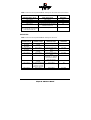
GDT6557RP
Valid connections and required GDTSETUP settings for channel A
External female
connector, 68 pin
Internal female
connector, 68 pin
Internal male connector
channel A, 50 pin
Channel A
termination
Occupied and end
terminated
Occupied and end
terminated
Occupied and end
terminated
Not occupied
Occupied and end terminated
Not occupied
Not occupied
Off or Auto
Not occupied
On or Auto
Not occupied
Occupied and end terminated
Occupied and end terminated
Occupied and end terminated
Occupied and both ends
terminated, i.e., channel A
connector is located between the two ends.
Not occupied
Off or Auto
Not occupied
Off
Not occupied
On or Auto
Not occupied
Occupied and end terminated
Not occupied
Not occupied
Not occupied
Not occupied
Occupied and end terminated
Occupied and both ends
terminated. Channel A
connector is located
between the two ends.
Not occupied
Not occupied
Not occupied
&KDSWHU%*'78VHU
V0DQXDO
Off or Auto
On or Auto
Off
On or Auto
Valid connections and required GDTSETUP settings for channels B to E (not channel A)
Internal female connectors channels B, C, D, E, 68 pin
Channels B, C, D and E
termination
Occupied and end terminated
Not occupied
Occupied and both ends terminated, i.e., channel B, C, D, E connectors are located between both ends
On
On
Off
%
66&6,,
,,'
'
All participants on the SCSI bus must have a unique identification number, that is, each
number can only be used once on a given cable. Each SCSI device is uniquely addressed
through its SCSI ID.
All participants of a SCSI bus must have a different SCSI ID.
The factory set SCSI ID of the ICP Controller SCSI channel is 7.
Up to 7 SCSI devices can be connected to a single SCSI bus. SCSI IDs are 0 to 6.
On hard disks, CD-ROMs, tape streamers, etc., the SCSI ID is normally set through jumpers
or small GDT switches. The ICP Controllers offer a far more comfortable method: software
switches in the GDTSETUP program allow you to easily set the SCSI ID of a GDT SCSI channel. It is recommended to leave the default ID value at 7. Some operating systems require
that the SCSI ID of certain SCSI device (e.g., tape streamer, CD-ROM) is set to a particular
value (for more information, please refer to the appropriate chapter in this manual).
(Note: More than 7 SCSI devices on a 16 Bit cable represent a performance bottle-neck for
disk arrays. The SCSI bus utilization is too high).
%
,,&3
366&6,$FF
FFHHVV
VVRRULHV
Order # Part Name
8840
Fast-SCSI
Bracket
8841
Wide-SCSI
Adapter
8842
Wide-SCSI
Bracket
8843
Wide/Ultra
Flat Ribbon
Cable
Narrow-Wide
Bracket
8846
Description
External SCSI connector with an internal 50 pin header and an external
50 pin HD SCSI connector (female)
16 Bit to 8 Bit SCSI adapter with a 50
pin header and a 68 pin HD SCSI
connector (male)
External SCSI connector with an internal and an external 68 pin HD
SCSI connector (female)
80 cm Wide/Ultra SCSI cable with
four 68 pin HD SCSI connectors
(male)
External SCSI connector with an internal 68 pin connector (female) and
an external 50 pin HD SCSI connector (female)
Application
Connection of an external Narrow/Ultra
SCSI subsystem with an internal Narrow/Ultra channel
Connection of Wide/Ultra SCSI devices
with an 8 Bit 50 pin flat ribbon cable
Connection of an external Wide/Ultra
SCSI subsystem with an internal
Wide/Ultra channel
Connection of up to 3 internal Wide/Ultra
SCSI devices per SCSI channel
Connection of an external Narrow/Ultra
SCSI subsystem with an internal
Wide/Ultra channel
%
(([DPSOHV
Below are some examples of correct SCSI cablings, SCSI terminations and SCSI-ID settings.
&KDSWHU%+DUGZDUH,QVWDOODWLRQ
2QH,QWHUQDO%LW6&6,'HYLFHRQ&KDQQHO$
&KDSWHU%*'78VHU
V0DQXDO
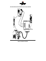
6HYHUDO,QWHUQDO%LW6&6,'HYLFHVRQ&KDQQHO$
&KDSWHU%+DUGZDUH,QVWDOODWLRQ
7ZR,QWHUQDO6&6,'HYLFHV%LWDQG%LWRQ&KDQQHO$
&KDSWHU%*'78VHU
V0DQXDO
2QH,QWHUQDO$QG2QH([WHUQDO6&6,'HYLFHERWK%LWRQ&KDQQHO$
&KDSWHU%+DUGZDUH,QVWDOODWLRQ
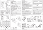
%,QVWDOOLQJWKH,&3&RQWUROOHU
Make sure that the ICP Controller is equipped with an appropriate SIMM. As already mentioned in section B.3 of this User's Manual it is not possible to operate the ICP Controller
without a SIMM.
Step 1
Switch off the PCI computer system and remove all cables (first of all the power supply).
Step 2
Following the instructions in the computer manual, open the case of the PCI computer, so
that you have easy access to the PCI expansion slots.
Step 3
Select a free PCI bus-master slot and remove the metal bracket, following the instructions
in your PCI computer manual. It is essential that the ICP Controller is plugged into a busmaster slot (it will NOT work in a slave or non-bus-master slot). Some motherboards have
only 1 bus-master slot.
Make sure that the selected slot has a sufficiently cooling airflow. Permanent overheating of
electronic devices decreases their life time drastically.
Step 4
Channel A of the ICP Controller has an internal and an external SCSI connector. If you wish
to connect SCSI devices to the internal as well as to the external SCSI connector of channel
A, disable the SCSI-bus termination of channel A by means of the GDTSETUP program (see
later on in this chapter). The SCSI-bus termination of the different SCSI channels of your
ICP Controller can be enabled or disabled through software-switches within the central
setup utility program GDTSETUP. When changing the SCSI-bus termination, the ICP Controller can remain in the computer.
Step 5
Push the ICP Controller firmly into the correct PCI bus-master slot. Make sure that the controller fits tightly into it, and that the external SCSI connector sticks out of the computer
case. Now, fix the ICP Controller by tightening the screw of its bracket.
Step 6
To connect internal SCSI devices, use the internal SCSI connectors of the ICP Controller (2,
or 3). You need 50-pin or 68-pin SCSI flat ribbon cables with appropriate connectors. Please
verify that the colored core of the SCSI flat ribbon cable connects PIN1 of the GDT SCSI
connector to PIN1 of the SCSI device. To connect an external SCSI device, an external round
cable is needed. Please make sure that the total length does not exceed the limits which are
determined by mode and transfer rate. Regardless of whether the SCSI devices are connected to the internal or the external SCSI connectors of the ICP Controller, you should only
use cables of highest quality in order to ensure an interference-free data transfer. Doublecheck that no other SCSI device has its SCSI-ID set to 7, as this is the SCSI-ID of the ICP
Controller (= SCSI IDentification number, assuming values between 0 and 7). If necessary, the ID of the GDT SCSI channels can be changed with the GDTSETUP program (see
later in this chapter). The SCSI-ID can be chosen directly on the SCSI device by setting DIP
switches or jumpers (please refer to the manual of the SCSI device). Furthermore, all SCSI
devices connected to a given SCSI channel must have different SCSI-IDs. Additionally, it is
important that the SCSI terminators are removed or switched off when more than one SCSI
device is operated together with the ICP Controller. Only the last and the first participant of
a SCSI channel (i.e., the two ends) may have SCSI terminators whereas all other participants
on the SCSI bus must have their terminators removed or - if possible - switched off. The
&KDSWHU%*'78VHU
V0DQXDO
jumpers TPA, TPB or TPC (= terminator power) on the ICP Controller are usually set. This
setting may only be modified if the terminator power on the SCSI cable is supplied by another SCSI device. The terminator power line on the SCSI cable may be used by SCSI devices which do not supply DC power to their own SCSI termination circuitry (e.g., external
SCSI terminator packs.).
Step 7
When installing internal SCSI devices, make sure that the slots of the SCSI devices have
sufficient air flow, and that the power consumption of all SCSI devices does not exceed the
capacity of the computer's power supply. An overloaded DC power supply has a poor DC
voltage quality (noise, ripple) and causes problems for all connected consuming devices.
Step 8
If required, you can connect the HDD-front-LEDs of the PCI computer system to the LED
connectors of the ICP Controller (for the pin assignment of these connector, see the appendix).
Step 9
Before the PCI computer system is switched on, you should check the following points over
again:
9
Is the SIMM plugged firmly into the SIMM socket ?
9
Is the ICP Controller plugged firmly into one of the PCI bus-master slots ?
9
Are the SCSI-IDs set correctly ?
(with no other device currently set to ID 7 ?)
9
Are the SCSI-bus terminators plugged/set correctly ?
(with currently terminated GDT SCSI channels ?)
9
Are the SCSI flat ribbon cables connected correctly ?
9
Are all SCSI devices installed properly and connected to the power supply
of the PCI computer system ?
Step 10
After having checked all the points in "Step 9", reconnect the PCI computer system to the
power supply. Do not close the computer case yet.
%,&3&RQWUROOHU)XQFWLRQ&KHFN
Before we put the ICP Controller into operation for the first time, we would like to spend a
few words on the PCI 2.x compatibility requirements a PCI computer system (especially the
motherboard and the motherboard's BIOS) should meet.
%
3
3&,
,[
[&&RPSDWLELOL
LOLWW\
\5
5HTXLUHPHQWV
A pre-condition for a flawless installation of PCI bus-master expansion cards (the ICP Controllers belong to this group of expansion cards) in a PCI motherboard is a 100% PCI 2.x
compatible System-BIOS.
&KDSWHU%+DUGZDUH,QVWDOODWLRQ
We have observed more than once that a motherboard declared fully PCI 2.x compatible
was equipped with a System-BIOS (located in an EPROM or FLASH-RAM) which was not
PCI 2.x compatible at all. To make up for this, many manufacturers of PCI motherboards or
PCI computer systems offer their customers a BBS mailbox system from where the latest
PCI-system-BIOS version can be downloaded by modem.
As PCI is a rapidly growing market and more and more bus-master expansion cards (high
performance disk and LAN controllers) are becoming available, we have no doubt that such
problems will be resolved very quickly by the respective system-BIOS manufacturer.
The System is fully PCI compatible.
If your PCI motherboard/computer is 100% PCI compatible, its PCI system-BIOS will, to a
large extent automatically (plug & play), carry out the configuration (e.g., mapping of the ICP
Controller's BIOS and DPMEM, assignment of a proper system IRQ to a PCI interrupt). This
means that the PCI computer system (with its motherboard and PCI system-BIOS) must
meet the following requirements:
1. The PCI computer system must automatically assign (map) the ICP Controller BIOS to
an adequate address in the lower, 1MB area of the computer system’s main memory.
2. The PCI computer system must map the ICP Controller’s Dual Ported Memory (needed
for high performance operation) to an adequate address in the lower, 1MB area of the
computer system’s main memory. In addition, it has to disable the shadowing of this
address <SPACE>.
3. Assigning a system IRQ to a PCI interrupt.
The PCI 2.x specification prescribes 4 PCI interrupts, called INT A, INT B, INT C and
INT D. A PCI interrupt must be assigned to a free (unused) IRQ of the PCI motherboard or computer. The ICP Controller is shipped with PCI INT A.
Depending on the manufacturer of the PCI computer system, there are several ways to
carry out this task:
automatically (automatic IRQ routing)
with the PCI System-BIOS setup program
with the PCI System-BIOS setup program and
jumper settings on the system motherboard
Depending on the BIOS manufacturer (e.g., Award, Phoenix, AMI etc.), the setup program is activated by pressing a certain key-combination shortly after the reset (cold
boot or warm boot). For detailed information on the key-combination and the jumpers’ locations and settings, please refer to the system manual of your PCI motherboard or computer.
The System is not fully PCI compatible.
Problems may occur if the motherboard and/or System-BIOS are not fully PCI 2.x compatible. The best remedy is to update the PCI system-BIOS to the latest version.
Furthermore, we have integrated into our GDT BIOS various routines (tricks) which remedy
the incompatibilities of some PCI system-BIOSes, at least with regard to the ICP Controller.
%
66ZLWFKLQJ
J2
2Q
QWWKH
H3
3&,
,&&RPSXWHU
U66\VWHP
Now, after having installed the ICP Controller and the SCSI devices, check whether the controller is working correctly. If the ICP Controller is the only controller in the computer system, set hard disks C: and D: to not available in the System-BIOS setup program of the
&KDSWHU%*'78VHU
V0DQXDO
computer. Normally, you can start the BIOS setup program by pressing a certain keycombination after switching on the computer. After switching on the PCI computer system,
pay attention to the LEDs of the ICP Controller.
9
If everything is installed correctly, the green LED "S" will light up when
switching on the PCI computer system. The green LED "S" (S for status) shows
that the ICP Controller is online. If this green LED does not react as described
above, switch off the PCI computer and double-check the correct installation
of the ICP Controller.
9
The electronic loudspeaker of the ICP Controller gives forth a series of 4 signals with a pause between the first two).
9
The other green LED "T" may flicker sometimes (it always lights up during
BUS-Master DMA transfers; the brighter it lights, the more DMAs).
9
The yellow LEDs indicate accesses to the SCSI devices. They also may flicker
occasionally as GDT scans the SCSI channels for existing SCSI devices. The
yellow LED "SCSI" flickers whenever a SCSI device on any of the ICP Controller's SCSI channels is accessed.
The GDT boot message appears. In the following example, a GDT6527RP Controller has
been detected in PCI slot 3, and it has 16MB of RAM ("16 MB RAM detected..".). On SCSI
channel A, a Quantum drive has been recognized, and, on channel B, a DLT2000XT
streamer.
*'73&,'LVN$UUD\&RQWUROOHU%,269HUVLRQ D
&RS\ULJKW&E\,&3YRUWH[&RPSXWHUV\VWHPH*PE+0DU
$OOULJKWVUHVHUYHG
%,26ORFDWHGDW[([()))
&RQWUROOHUVIRXQG6HOIWHVWV2.VFDQQLQJ6&6,%XV
>3&,@'30(0DW['['))),17$ ,54
>3&,@*'753+:/0%5$0N%N%)ODVK5$0
>3&,@6HULDO1R5$,'<1():9HUVLRQ 50DU
>3&,@&+1$,'/8148$1780;3:
>3&,@&+1%,'/81'/7;7
3UHVV&75/!*!WRHQWHU*'76(783
The single messages have the following meaning:
%,26ORFDWHGDW[([()))
Unlike ISA or EISA computers where the BIOS address of a peripheral expansion card is set
manually (ISA, jumpers) or with the help of a configuration file (EISA, cfg file) and the address space is determined by the user, the PCI system-BIOS automatically maps the BIOS of
a PCI compatible peripheral expansion card to a memory address. At each cold or warm
boot, it determines which address space to assign to the BIOS of an expansion card. The
message shown above reports the physical address occupied by the GDT BIOS. In our example, it is E000:0000 to E000:1FFF (E000 is the segment address). The GDT BIOS’ size is
always 8KB. This information is essential when installing Expanded Memory Managers under DOS and Windows. If the ICP Controller is run without its driver GDTX000.EXE, the GDT
&KDSWHU%+DUGZDUH,QVWDOODWLRQ
BIOS address space has to be excluded from the control of such a manager (for more details, see chapter C of this manual).
>3&,@
3&, device, bus system , slot. The PCI 2.x specification allows several PCI bus systems to
be present in one PCI computer. All ICP Controllers have been designed to support multiple
PCI bus system computers. The slot number indicated in the message above does not refer
to the 3rd PCI slot, but indicates that the ICP Controller is plugged into a slot which is the
third one the PCI chipset of the PCI computer can access. To determine which physical PCI
slot this corresponds to, consult the system manual of your PCI computer.
'30(0DW['['))),17$ ,54
'30(0stands for 'ual 3orted 0(0ory. The ICP Controller needs this 16KB address space of
the PCI Computer for the command communication. In our example, the address space begins at D000:0000 and ends at D000:3FFF (D000 is the segment address). As with the ICP
Controller BIOS, this mapping, is also automatically carried out by the PCI system-BIOS.
This information is essential when installing Expanded Memory Managers under DOS and
Windows. The GDT DPMEM address space has to be excluded from the control of such a
manager. (For more details, see chapter C of this manual). Furthermore, this messages tells
us that the PCI ,17$ of the ICP Controller has been assigned to the system,54. This assignment, is also carried out automatically if the PCI system-BIOS is 100% PCI 2.X compatible.
*'753+:/0%5$0N%N%)ODVK5$0
*'753+:/ stands for the type of ICP Controller found by the GDT BIOS. HWL
means Hardware level. 0%5$0indicates that the installed SIMM is a 16MB, non-parity
Fast Page Mode (FPM) SIMM. Depending on the type and size of the installed SIMM the
following messages are possible (xx = 4, 8, 16, 32, 64):
[[0%5$0
[[0%5$03
[[0%('25$0
[[0%('25$03
xx MB Fast Page Mode (FPM) SIMM without parity (i.e. 32 bit)
xx MB Fast Page Mode (FPM) SIMM with parity (i.e. 36 bit)
xx MB Extended Data Out (EDO) SIMM without parity (i.e. 32 bit)
xx MB Extended Data Out (EDO) SIMM with parity (i.e. 36 bit)
When a parity SIMM is installed this message is followed by: (&&3DULW\VXSSRUWHQDEOHG.
N%N%)ODVK5$0indicates the size of the installed Flash-RAM. "512kB" refers to the onboard Flash-RAM size. The "/0kB" stands for an empty Flash-RAM expansion socket (Feature
Socket A).
3UHVV&75/!*!WRHQWHU*'76(783
After pressing this hot-key, the message (QWHULQJ*'76(7833OHDVHZDLWappears. The SCSI
bus scan is completed and the built-in GDTSETUP configuration program is loaded. It allows you to configure RAID Array Drives.
%
77URXEOH
H66KRR
RRWWLQJ
If these messages do not appear on the screen, or if other problems occur after switching on
the computer system (screen remains dark etc.), you should check the entire installation
over again:
Are you using the correct SIM-module ?
(Minimum 4MB, 60ns or faster for FPM and 50ns for EDO)
Try another one.
&KDSWHU%*'78VHU
V0DQXDO
SIMM plugged firmly into the socket ?
Unplug it and plug it in again.
Is the ICP Controller plugged into a PCI bus-master Slot ?
Check this. If necessary, try another slot.
Is the SCSI flat ribbon cable OK ?
Check length, orientation and connectors. Try another cable.
Are the IDs of the SCSI devices adjusted correctly ?
Check the SCSI-IDs.
Have the terminators (SCSI terminators) of the SCSI devices, where requested, been removed ?
Check the SCSI termination.
Does the power supply of the SCSI devices work ?
Check the voltage (+5V, +12V).
If the PCI System-BIOS is not PCI 2.x compatible (see above), the ICP Controller BIOS
may display one or more of the following messages:
(i) The DPMEM has not been installed correctly.
(UURU
6\VWHP%,26QRW3&,FRPSOLDQWFRQWDFW\RXUPDLQERDUGVXSSOLHU
&RQWUROOHUDW[\KDVLQYDOLG'30(0DGGUHVV
7U\LQJWRDOORFDWHDIUHHDGGUHVV
)RXQGIUHHDGGUHVVDWDFFHSW"<HV1R$ERUW<
&DXWLRQWKLVDGGUHVVPXVWQRWEHXVHGE\DQRWKHUH[SDQVLRQFDUG
In this case, the system-BIOS has not installed the Dual Ported Memory of the ICP Controller correctly. Therefore, the ICP Controller will search for an adequate address. If you accept
the suggested address (<), the ICP Controller will install its DPMEM starting at this address.
Since this 16KB address space which starts at IUHHDGGUHVV must not be shadowed, you
might have to disable the shadowing manually in the system-BIOS setup program. In addition, make sure that this address space is not used by another expansion card. (This is a
work-around, not a solution. PCI 2.x is a well defined specification, and a fully compatible
system-BIOS should have assigned the DPMEM automatically.)
If the GDT BIOS could not find an appropriate address, the following message is displayed:
&DQQRWVHW'30(0DGGUHVVDERUWLQJ
In this event, you can try to select a new address after resetting the computer. If this fails,
too, there is no other way but to update the PCI system-BIOS.
(ii) The IRQ to PCI INT assignment doesn’t work properly.
:DUQLQJ
FRQWUROOHUDW[\6\VWHP%,26FRQILJXUHG,54=EXWXVHV8
This warning indicates a bug in the PCI System-BIOS, too: It did not succeed in correctly
assigning an IRQ to a PCI INT. The ICP Controller will function, but the GDT BIOS must not
be disabled whatsoever.
&KDSWHU%+DUGZDUH,QVWDOODWLRQ
(iii) The IRQ to PCI INT assignment doesn’t work at all.
(UURU
FRQWUROOHUDW[\FRXOGQRWUHDG,54VHWWLQJ
If this error message is displayed, the ICP Controller will not work.
In all these cases you should - in case (iii) you have to - update your PCI system-BIOS as
soon as possible.
%&KHFNLQJWKH,&3&RQWUROOHU&RQILJXUDWLRQ
As mentioned before, these settings can be changed through soft-switches in the ICP Controller setup program GDTSETUP. All settings are permanently stored on the ICP Controller.
The following table shows the various options and the possible settings.
Function
(*)
Cache On
(*)
Delayed Write On
BIOS
BIOS Warning Level
Memory Test
SCSI-ID
SCSI Termination
(*)
Possible Settings
On, Off
On, Off
Enabled, Disabled
All messages, Fatal errors
No Test, Standard, Double Scan, Intensive
0,1,2,3,4,5,6,7
On, Off, Auto
Factory Setting
On
On
Enabled
Fatal errors
Standard
7
On
Can also be changed with the GDTMON online utility.
%
//RDGLQJ*'76(783
As already mentioned before, there are two different possibilities to load GDTSETUP. Basically, these two possibilities are based on two different variants of the same program: One
which is integrated into the FLASH-RAM of the ICP Controller and another with is simply an
EXE program loadable under MS-DOS.
Loading GDTSETUP from the FLASH-RAM is very comfortable, since it requires nothing
else, but pressing the <CTRL><G> key combination after switching on the PC.
Loading GDTSETUP under MS-DOS becomes necessary, when you want to use GDTSETUP's
integrated partitioning functions, or when you have totally disabled the GDT's BIOS (which
includes the GDTSETUP variant loadable from FLASH-RAM).
If you want to load GDTSETUP under MS-DOS you have to load the device driver GDTX000
first. This can be done in two ways:
1. Starting the device driver from the DOS-command level by typing GDTX000<ENTER>
2. Starting the device driver automatically by means of the CONFIG.SYS
(DEVICE=GDTX000.EXE)
Note: GDTSETUP as well as GDTX000 are on the System Disk - DOS.
The header of the GDTSETUP program indicates with a letter after the version number,
whether GDTSETUP was loaded from disk or from Flash-RAM:
"R" for GDTSETUP loaded from the Flash-RAM after switching on the computer
"D" for GDTSETUP loaded from Disk, i.e., under MS-DOS.
&KDSWHU%*'78VHU
V0DQXDO
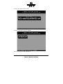
The main menu appears. Select Controller.
Select the ICP Controller and press <ENTER>.
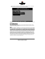
Press the <F2>-key for the Advanced Setup.
&KDSWHU%+DUGZDUH,QVWDOODWLRQ
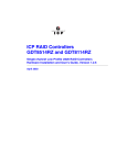
Select Configure Controller and press <ENTER>.
The fields can be selected by moving the cursor keys Ç and È . The values can be changed
by pressing <ENTER> and selecting a new setting. Leave this menu by pressing the <ESC>key.
In order obtain optimum performance from your ICP Controller, it is essential that the Cache
and the Delayed Write options of the ICP Controller are set 21, too. If you should find different settings here, we recommend that they be changed now.
&KDSWHU%*'78VHU
V0DQXDO
%
8
8SG
SGD
DWLQJ
JWWKH
H,,&3&RQWUROO
OOHHU
U:
:LWK
K1
1HZ
Z))LUPZDUH
HD
DQG
G%
%,26
69
9HUVLRQV
The firmware, the BIOS and the GDTSETUP program of the ICP Controller are stored in a
Flash-RAM which is part of the ICP Controller hardware. In contrast to EPROMs, FlashRAMs can be re-programmed many times and without the complicated UV-light erasing
procedure. Thus, both software modules can be easily updated without having to remove
the controller from its PCI slot. Firmware and BIOS are part of the *'7B53): file. The file
has an extension (e.g., GDT_RPFW.009) which indicates the version stepping. The latest version of the this file can be downloaded either from our 24h BBS (+49-(0)-7131-5972-15) or
from our Website http://www.icp-vortex.com. We recommend that you also download the
packed files which contain the latest programs/drivers for the operating system used on
your system. Observe the following order when carrying out the updating procedure:
1. Get the latest GDT_RPFW file for the ICP Controller (download it from our BBS, or our
Website, or ask for an upgrade disk if you do not have a modem). The file does NOT
need to be expanded !
2. Format a 3.5" HD disk (1.44MB) and copy the GDT_RPFW file on this disk.
3. After loading GDTSETUP (from Flash-RAM or from disk under MS-DOS) select the desired ICP Controller for the firmware update and press the <F2>-key to enter the Advanced Setup.
4. Select Configure Controller and thereafter Firmware Update. Insert the disk with the firmware
file into drive A. GDTSETUP loaded from the Flash-RAM will display a list of the valid
files found on the disk. If you have loaded GDTSETUP from disk you have to enter the
path "A:", first.
5. The update process starts as soon as the desired GDT_RPFW file has been selected.
Strictly observe the messages and instructions of GDTSETUP. It is extremely important
&KDSWHU%+DUGZDUH,QVWDOODWLRQ
that the system is not switched off or reset during the update process. It is very likely
that this would cause the ICP Controller to become inoperable.
The new versions of the GDT Firmware, the BIOS and GDTSETUP are available after the next
cold-boot.
%
$
$GG
GGLLWLRQDO
O1
1RWHV
After having completed the installation, you can close the computer case again. The following chapters explain how to configure the SCSI devices and how to use the ICP Controller with various operating systems.
1RWH
Before the computer is switched off or a hard reset is carried out, the ICP Controller
first has to write the current contents of its cache RAM back to the hard disk(s) (flush).
The computer may only be switched off or reset after all hard disk accesses have been
completed. If this is not observed there is a high risk of data corruption and data loss !
A good indication for hard disk activity is the front HDD-LED of your computer system (presuming it is connected with the corresponding pin grid header of the GDT PCB). In addition,
all GDT drivers (i.e. for all supported operating systems) are designed to perform a cache
flush when a regular system shutdown is initiated (e.g., Under NetWare: Down and Exit; Under DOS: CTRL-ALT-DEL; Under UNIX: Shutdown). They will show a message similar to the
following "Flushing Controller Cache". As long as this message is displayed you must not switch
off or reset your PCI computer. For Windows 95, Windows NT and OS/2 you may switch off
or reset the computer as soon as the operating system message is displayed, which indicates that it is safe, to turn off the computer now.
&KDSWHU%*'78VHU
V0DQXDO
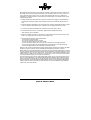
1RWH
The RISC CPU of the ICP Controller is equipped with a cooler consisting of a heat sink and a
ball-beared DC micro fan. The cooler keeps the operating temperature of the CPU within the
specified limits. The air intake is on the top of the fan. The air flows through the fins of the
heat sink and leaves it on the left and right side.
In addition, it is necessary that the whole ICP Controller is positioned in a constant airflow.
Normally, good server enclosures have extra fans for the motherboard expansion slot area.
Under normal conditions, the DC micro fan has a calculated life-time of more than 5 years
(24 h operation per day and 365 days per year). In case of a fan failure, the temperature increases. Once it passes a certain threshold value, the ICP Controller sends a message to the
operator. Exchanging the DC micro fan is simple: The fan and the heat sink are mounted
with two M3 screws which can be easily removed. The fan is supplied with DC voltage
through a small connector on the GDT printed circuit board.
The cooler on your ICP Controller may look different from the one on pages of this manual.
Depending on the type of i960 Rx CPU installed on the ICP Controller, with some models, the
cooler is completely missing. This is intended !
All variants fully comply to the specifications laid down in this User's Manual.
&KDSWHU%+DUGZDUH,QVWDOODWLRQ
This page is intentionally left blank.
&KDSWHU%*'78VHU
V0DQXDO