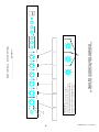
1
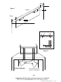
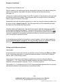
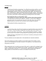
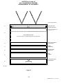
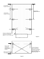
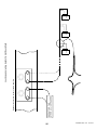
Connevans
Solutions to improve the quality of life
This product may be purchased from Connevans Limited secure online store
at www.DeafEquipment.co.uk
DeafEquipment.co.uk
Solutions to improve the quality of life
40SFSYS 24, 26 and 28
USER GUIDANCE NOTES AND
ASSEMBLY INSTRUCTIONS
V 2.1 (new cabinet)
B40SFSYS2K Hall Soundfield Installation v 2.1 23.05.08
CONNEVANS LIMITED
HALL SOUNDFIELD SYSTEM
40SFSYS 24, 26, 28
ASSEMBLY INSTRUCTIONS AND
USER GUIDANCE NOTES
Upon receipt check all the packages for damage and check the contents,
You should receive the following:
Main Equipment and Accessories.
1 x 12, 15 or 18U Wall mounting cabinet (Z19??UWALL)
1 x 1U Shelf with holes for Radio Receivers (48S4.16RK)
1 x 1U Shelf with back (Z191USHELZ)
1 x Microphone Line Mixer (+MMX-602)
1 x Stereo Power Amplifier (.INR300)
4, 6 or 8 x Loudspeakers (40SFJBLC1P or C1W)
Drum of Speaker Cable (100m) (*E627)
1 x Handheld Radio mic’ Transmitter and Receiver
1 x Beltpack Radio mic’ Transmitter and Receiver
1 x Boom mic’ stand (40SF*M07)
1 x 2U Lockable drawer unit – with hook. (Z192UDRAWH)
1 x 8-way Power Distribution Unit (Z198WAYPDU)
1 x Front Patch Panel (A40SFPP01)
1 x Collar worn mic’ for belt pack unit
Marker Cable Ties (Packet of 100) and Marker Pen (*F054BLPEN)
4, 6 or 8 x Speaker Safety Wire and screw eye
4 x XLR Plug to XLR Socket lead. 700mm (XLRE.7MBK)
1 x Stereo lead. 2x Phono plugs to 2x stackable Phono sockets (*A114F*)
3 x Stereo lead. 2x Phono plugs to 2x Phono sockets (*A114*)
1 x fmGenie neck harness and pouch (FMG621)
1 x Soundfield to fmGenie Tx lead (XSIBFMG2)
1 x Quad battery charger (22684)
4 x Rechargeable batteries (2267NMH)
4 x M6 x 10 Rawlbolts (ZFRB0810)
19” Panel captive nuts and screws (M6 x 25mm) 7 Pks of 4 (Z19FIX1)
1 x Antenna mounting plate assembly (A0SF4AK)
-2CONNEVANS LIMITED 54 Albert Road North, Reigate, Surrey RH2 9YR
Tel 01737 247571 Minicom/Textphone 01737 243134 Fax 01737 223475
B40SFSYS2K Hall Soundfield Installation v 2.1 23.05.08
USER GUIDELINES
Front Panel Controls and Setting-up the system.
The radio microphone receiver output is connected to the Mixer.
(You may also add a CD or Cassette player or your existing ‘Coomber’ unit or the input from a TV or other existing AV equipment).
The output from the Mixer is fed into the amplifier.
The output from the amplifier drives the loudspeakers.
Because the outputs going into the Mixer from different microphones, and any other
equipment connected as part of the system, are different - and because no two Halls
are the same - all of these levels are adjustable (see below).
Each input to the Mixer needs to be adjusted so that the level of the input going into the
amplifier is ‘balanced’. i.e. So that all the microphones sound the same and that any other
input - Eg. Music from a CD player – does not drown out someone using a microphone.
The overall Mixer output level may then be adjusted before it goes into the Amplifier.
The amplifier output to the loudspeakers may then, also, be adjusted using the two volume
controls.
In addition, there are (three) controls that may be used to set ‘Tone’ adjusting Low, Midrange and High frequency sounds;
Set all three of these controls to the mid-way position (12:00 o’clock) to start
with, and then adjust (only slightly) forwards or backwards to suit individual
voice characteristics or Hall acoustics.
These controls will have been set up correctly by the installers and they should seldom
need adjusting. At the back of this guide you will find a sheet on which you can make a
record of the preferred settings, for future use.
If for any reason the controls have been altered from their original settings the following
instructions allow you to change any of the user adjustable controls in order to obtain the best
results for YOUR hall.
-3CONNEVANS LIMITED 54 Albert Road North, Reigate, Surrey RH2 9YR
Tel 01737 247571 Minicom/Textphone 01737 243134 Fax 01737 223475
B40SFSYS2K Hall Soundfield Installation v 2.1 23.05.08
Because no two Halls are the same this is intended as a guide only. You will need to set
the controls, using these instructions, in order to obtain the best results for your Hall.
It will prove very useful if you can carry out the setting up with a colleague or, better still, with a group - so that you
can all get a ‘feel’ for how the system works and how it should sound.
1.
Set the two volume controls on the Amplifier low, or to the 9 o’clock position.
2.
Set the output ( L and R ) from the Mixer to the Amplifier to 3 o’clock.
(Numbered 14 in the Manufacturers Handbook)
3.
Set the Mixer control for the collar worn microphone (Channel 1) to 12 o’clock.
4.
Set the Mixer control for the Handheld microphone (Channel 2) to 12 o’clock.
DO NOT ACCEPT THESE AS ‘DEFAULT’ SETTINGS THIS IS SIMPLY A ‘STARTING-POINT’ FROM
WHICH TO ADJUST THE CONTROLS TO SUIT YOUR HALL.
Make a note of the settings for your system on the sheet provided on Page 9.
Switch-on the system at the mains, and make sure that the radio microphone receivers are on
and that both the Mixer and the Amplifier are also switched on.
Although the amplifier and the mixer have their own on/off switches the two Radio Receivers and the
battery charger do not. So, it is quite in order, and much easier, to use the switch on the mains socket as
a ‘master’ on/off switch - for the whole system.
However, you will need to plug the battery charger in to a separate switched socket so that you
may still charge the rechargeable batteries even when the system is not in use.
Collar worn microphone
5.
Plug the collar worn microphone into the beltpack transmitter unit, fit the microphone
around your neck and adjust it so that it is comfortable to wear with the mic’ capsule in
front of you, approximately 80mm to 100mm ( 3” to 4” ) from you mouth.
If you have the microphone too close to your mouth there will be a marked reduction in
the amount of speech that gets into the microphone as you turn you head sideways. If
you have the microphone too far away you will need to increase the level (using the
control on the front of the Mixer) to a point where you are almost guaranteed to get
‘feedback’ wherever you are standing in the Hall.
6.
Switch on the beltpack transmitter.
Note that the green LED display (next to the green ‘Power On’ LED on the appropriate,
matching, Receiver unit will light - This indicates that the receiver is successfully getting
a radio signal from the transmitter. Also note that the two yellow LED’s to the right of
the display will blink alternately, indicating that the signal is switching between the two
channels – see the note on page 11.
-4CONNEVANS LIMITED 54 Albert Road North, Reigate, Surrey RH2 9YR
Tel 01737 247571 Minicom/Textphone 01737 243134 Fax 01737 223475
B40SFSYS2K Hall Soundfield Installation v 2.1 23.05.08
7.
Without raising your voice speak into the microphone – as if you were talking to
someone at about arms length from you.
You should be only just aware that there is sound coming out of the loudspeakers.*
Check that your voice does not trail away too markedly when you move your head from
side to side - away from the microphone. If you find that this happens i) move the
microphone slightly further away and ii) adjust the input control for Channel 1 up
(clockwise) slightly. If you find that you get ‘feedback’ then adjust the Mixer Output
down (anti-clockwise).
*If you can hear yourself clearly then the system is too loud – turn the volume (on the
Amplifier) down a little. Remember this is a ‘Soundfield System’ not a Public Address
System.
Handheld microphone
8.
Switch on the handheld microphone and hold the microphone approximately
30cm to 35cm ( 12” to 14” ) from you mouth then, without raising your voice – as if
talking to someone at about arms length away, speak into the microphone.
Once again, you should only just be aware that there is sound coming out of the
loudspeakers.*
The sound from the handheld microphone should be about the same as from the collar
worn mic’. If it is markedly quieter or louder then adjust the input control for Channel 2
up or down as appropriate.
Again, if you can hear yourself clearly then the system is too loud – turn the volume (on
the Amplifier) down a little. Remember this is a ‘Soundfield System’ not a Public
Address System.
* The whole idea of a Soundfield System is to provide a comfortable level of sound for
everyone within the space to hear the person speaking clearly.
When setting up the radio microphones, and generally when familiarising yourselves with this
equipment try and make sure that there is a group of you (or at least two!).
People are often surprised at how different they sound when they listen to themselves through
loudspeakers, try and share this experience with others and have fun whilst you get to know
your way around the various different controls and switches. Pass the microphones around
the group, try turning the volume up and down, play some music through the system, but
always remember when your are using this system for speech, for teaching, that if you can
clearly hear your own voice then the volume setting is a little too loud and you should turn it
down (see notes above).
DO NOT ACCEPT THESE AS ‘DEFAULT’ SETTINGS THIS IS SIMPLY A ‘STARTING-POINT’ FROM
WHICH TO ADJUST THE CONTROLS TO SUIT YOUR HALL.
Make a note of the settings for your system on the sheet provided at the back of this guide
-5CONNEVANS LIMITED 54 Albert Road North, Reigate, Surrey RH2 9YR
Tel 01737 247571 Minicom/Textphone 01737 243134 Fax 01737 223475
B40SFSYS2K Hall Soundfield Installation v 2.1 23.05.08
Auxiliary equipment (Eg. CD or Cassette payer, AV presentation unit, ‘Coomber’ unit)
9.
Depending on how many Radio Microphones you have in your system any auxiliary
equipment will be connected using the next vacant channel on the Mixer. With a tape or
CD playing in your machine the sound volume from the additional equipment should
match the microphones – as set up above. If necessary, use the Mixer control for the
appropriate Channel to adjust the input to the mixer ‘up’ or ‘down’ as necessary.
This control may be used like a volume control to ‘fade’ music in/out during productions/presentations.
10.
Once you have matched the input from the microphones, and any additional equipment,
and the output from the Mixer to the Amplifier is set so that ‘feedback’ is not a problem
the overall loudness of the whole system may be adjusted using the volume controls on
the Amplifier – so that there is an even spread of sound throughout the hall, and the
person speaking is only barely aware of their own voice. See notes above).
As a general rule these controls should be adjusted together so that they are both set to
the same position. If necessary (because, for example, of the unusual shape or layout
of your hall) it is quite acceptable to have them set at different values.
If you want to use the system, and find that there are no charged batteries available for the
radio microphones, it is quite in order to use Alkaline batteries as an alternative – and we
would recommend keeping a stock of Alkaline batteries for just such an eventuality!
As a guide, you should find that you get approximately 8 to 10 hours use from a set of Alkaline
batteries. A set of rechargeable batteries should last approximately 3 to 4 hours.
Re-broadcasting the System output from a Radio Aid Transmitter:
For fmGenie Radio Aids we have supplied a Soundfield to fmGenie connecting lead
(XSIBFMG2).
-
Locate the Phono sockets on the front panel marked ‘Radio Aid Out’.
-
Connect the Phono Plugs into the sockets on the front panel.
-
Plug the 2.5mm Jack into the Ext Mic socket on the fmGenie Transmitter.
Place the Transmitter into its pouch and hang the pouch from the hook provided on the front of
the drawer unit.
For other Radio Aids, including the Connevans CRM220, please contact Customer Services
(01737 247571) for details of the appropriate lead(s).
-6CONNEVANS LIMITED 54 Albert Road North, Reigate, Surrey RH2 9YR
Tel 01737 247571 Minicom/Textphone 01737 243134 Fax 01737 223475
B40SFSYS2K Hall Soundfield Installation v 2.1 23.05.08
For those who might wish to record the output from their Soundfield system we can
supply an adaptor lead (E.g. *A114AA*)
Connect the Phono plugs to the sockets marked ‘Record Out’ on the front panel.
-7CONNEVANS LIMITED 54 Albert Road North, Reigate, Surrey RH2 9YR
Tel 01737 247571 Minicom/Textphone 01737 243134 Fax 01737 223475
B40SFSYS2K Hall Soundfield Installation v 2.1 23.05.08
-8CONNEVANS LIMITED 54 Albert Road North, Reigate, Surrey RH2 9YR
Tel 01737 247571 Minicom/Textphone 01737 243134 Fax 01737 223475
B40SFSYS2K Hall Soundfield Installation v 2.1 23.05.08
9
B40SFSYS2C v.01
1 12.03.07
IN / OUT
2
IN / OUT
3
IN / OUT
4
IN / OUT
5
IN / OUT
6
11
IN / OUT
PLEASE REFER TO THE MANUFACTURERS HANDBOOK FOR
MORE DETAILS ON USER SELECTABLE FRONT PANEL CONTROLS.
and needs to be 'OUT' when a Cassette player, CD player or a
'Coomber' unit is connected - using the RCA Phono sockets.
be 'IN' when using the XLR Mic' input (on the rear of the Mixer)
( marked 11 in the Mixer Instructions Book - page 3 ), needs to
The input selector button on the front panel of the Mixer
IMPORTANT NOTE:
IN / OUT
IN / OUT
1
………………………….……. DD/MM/YY ...
MIXER CONTROLS - 'DEFAULT' SETTINGS
IN / OUT
8
- 10 CONNEVANS LIMITED 54 Albert Road
R
North, Reigate, Surrey RH2 9YR
Tel 01737 247571 Minicom/Textphone 01737 243134 Fax 01737 223475
INSTALLATION.
Fixing the wall cabinet.
Decide on best position for the cabinet:
•
Things to consider.
•
•
•
•
•
•
•
•
At the front or the back of the Hall, but with a clear view of the Hall – for the Aerials.
Leave enough clear space so that the door can be opened freely.
Away from large metal objects (E.g. Steel beams and column supports Etc.).
Not immediately above or too near to a radiator or room heater.
Near to an existing 13A Mains Power socket (or you could have a new spur fitted).
Low enough so that you can get to the equipment controls and the drawer unit.
Not so low that it becomes a hazard (with or without the door open).
Please consider all of the uses for the Hall, and consult with other members of staff.
Unlock and remove the door and both the side panels from the wall cabinet (take great care not to
lose the small spacer that you will find under the lower hinge pin!). Unscrew the two retaining screws and
remove the hanging bracket at the rear of the cabinet.
Taking account of the overall height of the cabinet being installed (12U = 640mm. 15U = 770mm)
use a spirit level and the wall bracket, as a template, to mark the top pair of holes for fixing the
cabinet to the wall. See figure 1, page 12.
Using a 12mm masonry bit drill a 12mm x 50mm hole at each of the marked positions and fit
the bracket to the wall with two of the Rawlbolts supplied. Hang the cabinet on the wall
bracket and mark the position of the two lower fixing holes. Remove the cabinet, to drill and
insert the Rawlbolts, then replace the cabinet and secure to the wall.
Fit the antenna mounting plate assembly (as shown in figure 2, page 12) and making sure
that it is fixed securely. Attach the four antennae to the sockets on the mounting plate, note
that the two pairs are staggered - front to back - and arrange them so that they are angled
approx 60º from horizontal – as shown in figure 2.
Having the antennae not touching and not vertical is essential, because these
transmitters and receivers are both ‘diversity’ and each operates on two channels (so
as to avoid creating radio reception ‘dead spots’ around the Hall). Whichever of the two
channels operating at any given moment is indicated by the two yellow LED’s on the front
panel of the receiver – see also page 4.
- 11 CONNEVANS LIMITED 54 Albert Road North, Reigate, Surrey RH2 9YR
Tel 01737 247571 Minicom/Textphone 01737 243134 Fax 01737 223475
B40SFSYS2K Hall Soundfield Installation v 2.1 23.05.08
35mm
Figure 1
530mm
35mm
35mm
Figure 2
Front left and rear right
Front
left
rear right
connect
to and
Transmitter
1
connect to Transmitter 1
Rear left and front right
connect to Transmitter 2
- 12 CONNEVANS LIMITED 54 Albert Road North, Reigate, Surrey RH2 9YR
Tel 01737 247571 Minicom/Textphone 01737 243134 Fax 01737 223475
B40SFSYS2K Hall Soundfield Installation v 2.1 23.05.08
Fixing the loudspeakers.
Decide on the location for the loudspeakers (see below and figure 3, Page 23) and fix them to
the wall using the brackets supplied and, at the same time, attach the safety eye to the wall
and secure to the speaker using the safety cable supplied.
Remember, when installing speakers for a Hall Soundfield System,
try not to “think sound”, but try to “think light”.
Imagine that your intention is to give an even spread of light throughout the Hall, and
place the loudspeakers accordingly.
Typically, for a 6-speaker system in a rectangular Hall, locate a speaker on to the longest wall
half way between the two end walls and then two more on the same wall at a distance
approximately 1/3 the total length of the hall away from the centre speaker, one to the left and
one to the right hand-side. Repeat for the opposite wall.
Speakers should be fixed at between 3m and 4m from the floor.
Once you have attached the speaker to the bracket and connected the wires ‘aim’ the speaker
at a point roughly equivalent to a point just in-board from the angle where the floor and the wall
opposite meet. Using the tool supplied, tighten the locking ring to fix the speaker in place.
See figure 3 Page 23
Using the drum of speaker cable supplied connect up the loudspeakers, as per the notes and
drawing (see page 25) supplied. Bring the wires back to the wall cabinet for connection to the
output terminals on the rear of the amplifier, passing through the cable entry point in antenna
mounting plate.
- 13 CONNEVANS LIMITED 54 Albert Road North, Reigate, Surrey RH2 9YR
Tel 01737 247571 Minicom/Textphone 01737 243134 Fax 01737 223475
B40SFSYS2K Hall Soundfield Installation v 2.1 23.05.08
BEFORE
AFT
AFTER
- 14 CONNEVANS LIMITED 54 Albert Road North, Reigate, Surrey RH2 9YR
Tel 01737 247571 Minicom/Textphone 01737 243134 Fax 01737 223475
B40SFSYS2K Hall Soundfield Installation v 2.1 23.05.08
Equipment installation.
Fitting the Power Distribution unit:
With the cabinet on the wall remove the two vertical rails at the rear of the cabinet, leaving the
captive nuts in position, and replace the rails so that they are the other way around
(see page 14).
Using a set of captive nuts and screws fix the PDU in position 1U below the top of the rails with
the sockets facing into the cabinet. Bring the mains lead out through the floor of the cabinet
ready to plug into the nearby 13A socket
Assemble the two radio microphone receivers on to their tray, using the screws provided in the
kit, and as shown in figure 4, page 19. Take this opportunity to set the channels and adjust
the ‘Mute’ and ‘Gain’ levels (see notes below).
Using the captive nuts and screws, from the accessory pack, install the equipment as shown
by the drawing on figure 5 on, page 17. Remember that the Patch Panel (A40SFPP01 must
be fitted above the amplifier (this location provides a void above the amplifier that assists with
convection ventilation for the amplifier) and below the Mixer (so that the accessories sockets
are in line with their respective controls).
As the equipment is installed into the cabinet connect it together, with the cables supplied as
per the illustration Figure 6 on page 21, and using the cable marker ties (supplied) to identify
each lead. See, also, the important notes on setting-up radio receivers, below.
Setting up the Radio microphones:
RECEIVERS
On the rear panel of each radio receiver you will find a control for setting the ‘Mute’ and ‘Gain’
levels. Using finger and thumb, or a small flat bladed screwdriver, set the Gain to Minimum
and the ‘Mute’ to the mid-way position.
Next to the dc Power input socket there is a small rotary control for setting the different
CHANNELS (1 – 16). Using a small flat bladed screwdriver set these controls to two different
channels for the two receivers (Typically 1 and 2 - as shown in figure 6).
The numbers 1 to 16 correspond to the 16 UHF frequencies pre-programmed into the receiver
and these are detailed in the manufacturer’s instructions booklet.
- 15 CONNEVANS LIMITED 54 Albert Road North, Reigate, Surrey RH2 9YR
Tel 01737 247571 Minicom/Textphone 01737 243134 Fax 01737 223475
B40SFSYS2K Hall Soundfield Installation v 2.1 23.05.08
TRANSMITTERS:
Beltpack
Carefully open the battery compartment – by sliding the cover down and then, once it is
clear of the catch, hinge it upwards. Above the space for the battery there are three
user adjustable controls; On the left is a small slide switch (‘INST’ for instrument and
‘MIC’ for Microphone). Make sure that this switch is in the ‘MIC’ position. Next to this is
the control for selecting the channel. Using a small flat bladed screwdriver carefully turn
this control to the number corresponding with the matching receiver in the cabinet.
On the right-hand side is a control marked ‘GAIN’.
This will have been pre-set at the factory and should be at the mid-way position.
It is unlikely that you should need to adjust it. However, if you do need to adjust the
gain please refer to the manufacturer’s instruction book and, using a very small flat
bladed screwdriver move the control clockwise or anti-clockwise as required.
Finally replace the battery compartment cover.
Handheld
Turn the locking collar to the left (anti-clockwise) and carefully slide the outer shell of the
body down, to reveal the battery compartment and small rotary control (similar to the
one on the rear panel of the receiver). Using a small flat bladed screwdriver, carefully
turn this control to the number corresponding with the matching receiver in the cabinet.
Replace the battery compartment cover, and secure it in place by returning the collar to
the ’locked’ position.
For more detailed instructions please refer to the manufacturer’s instruction handbook.
Once all the equipment has been installed and connected inside the wall cabinet, and the
wires from the loudspeakers have been connected to the amplifier, you can replace the two
side panels and the door.
When replacing the door it may be hung to open ‘left-to-right’ or ‘right-to-left’ as dictated by the
location. Simply insert the lower hinge pin into its socket – remembering to replace the small
spacer removed earlier (see page 11) – and then pull the upper hinge pin back against its
spring, position over the socket in the chassis, and release to secure the door.
- 16 CONNEVANS LIMITED 54 Albert Road North, Reigate, Surrey RH2 9YR
Tel 01737 247571 Minicom/Textphone 01737 243134 Fax 01737 223475
B40SFSYS2K Hall Soundfield Installation v 2.1 23.05.08
40SFSYS24, 26 and 28
HALL SOUNDFIELD SYSTEMS
ARRANGEMENT OF EQUIPMENT
Antenna plate assembly
1U
48S4.16RK with
2x Radio Receivers
8-Way Power Distribution,
at rear of cabinet. (1U)
4U
VOID ABOVE SHELF
(Provides the space for additional equipment to be added later).
1U
SHELF WITH BACK
Z191USHELZ
1U
MIXER
+MMMX602
1U
PATCH PANEL
A40SFPP01
AMP
.INR300
2U
2U DRAWER UNIT
Z192UDRAW
2U
12U Total
Figure 5
17
B40SFSYS2K v1.0 12.11.07
- 18 CONNEVANS LIMITED 54 Albert Road North, Reigate, Surrey RH2 9YR
Tel 01737 247571 Minicom/Textphone 01737 243134 Fax 01737 223475
B40SFSYS2K Hall
19
9
B40SFSYS2K v1.0 12.11.0
1U Shelf with holes.
48S4.18RK
Two Trantec Receiver Units.
Built-in spacers
figure 4
M3 x 10 Cheesehead screws x 8
GUIDE FOR FITTING THE TWO TRANTEC RECEIVERS TO THEIR SHELF.
Assembly guide.
07
- 20 CONNEVANS LIMITED 54 Albert Ro
oad North, Reigate, Surrey RH2 9YR
Tel 01737 247571 Minicom/Textphon
ne 01737 243134 Fax 01737 223475
40SFSYS24, 26, 28 - HALL SOUNDFIELD SYSTEMS
INTERCONNECTION OF EQUIPMENT
MUTE SETTING
(MID WAY)
GAIN SETTING
(MIN)
CHANNEL SELECTOR
dc POWER INPUT
ANTENNA CONNECTIONS
OUTPUT TO MIXER
2
1
2x XLRE.7MBK
XLR Plug to XLR Socket
Lead - 700mm
2x *A114*
Phono plug to
Phono plug lead.
2x XLRE.7MBK
XLR Plug to XLR Socket
Lead - 700mm
Shelf with back.
6
5
3
4
2
1
Patch panel
A40SFPP01
6
5
3
4
1x *A114F* Phono Plug to Stackable Phono Plug lead
and 1x *A114* Phono plug to Phono plug lead.
STEREO
BRIDGED
'Stereo' or 'Bridged Mono' selector
switch. Set to 'Stereo'
Please refer to manufacturers
instructions for more detailed
information, if reequired.
SPEAKER WIRES.
White with black tracer to Black.
White (only) to Red.
Z192UDRAW - 2U Drawer Unit
Figure 6
Page 21
B40SFSYS2K v1.0 12.11.07
- 22 CONNEVANS LIMITED 54 Albert Road North, Reigate, Surrey RH2 9YR
Tel 01737 247571 Minicom/Textphone 01737 243134 Fax 01737 223475
B40SFSYS2K Hall Soundfield Installation v 2.0
One sixth the
length of the Hall
One half the
length of the Hall
One third the
length of the Hall
If there is a Stage Area then
angle the front speakers
approx 5° to 10° in to the Hall.
Figure 3
Not less than
3m and not
more than 4m
from the floor of
the Hall.
Point the Speakers
down, into the Hall,
aiming for an imaginary
point just inside from
where the opposite wall
N.B. No two Halls are the same and it is not alwa
ays possible to locate the speakers
thefloor
idealmeet.
location.
andinthe
The diagrams above are given as a guide as to the result that you are aiming to achieve.
Page 23
- 24 CONNEVANS LIMITED 54 Albert Road North, Reigate, Surrey RH2 9YR
hone 01737 243134 Fax 01737 223475
Tel 01737 247571 Minicom/Textph
25
B40SFSYS2C v.01 12.03.07
REPEAT FOR THE
OTHER 2, 3 or 4 SPEAKERS
Speaker connections at rear of audio amplifier
RED
BLACK
RED
BLACK
Loundspeaker wiring details for Hall Soundfield
BLACK
RED
- 26
2 CONNEVANS LIMITED 54 Albert Ro
oad North, Reigate, Surrey RH2 9YR
Tel 01737 247571 Minicom/Textpho
one 01737 243134 Fax 01737 223475
NOTES
Settings. ………………………….. (DD/MM/YY)
Mic’ ONE
Style* …………………………. Frequency ………………….
Mic’ TWO
Style* ………………...………. Frequency ………………….
Mic’ THREE Style* …………………………. Frequency ………………….
Mic FOUR
Style* …………………………. Frequency ………………….
* Headband / Handheld / Collar / Lapel-Tie clip / Handheld(wired)
- 27 -
CONNEVANS LIMITED 54 Albert Road North, Reigate, Surrey RH2 9YR
Tel 01737 247571 Minicom/Textphone 01737 243134 Fax 01737 223475
B40SFSYS2K Hall Soundfield Installation v 2.1 23.05.08
- 28 CONNEVANS LIMITED 54 Albert Road North, Reigate, Surrey RH2 9YR
Tel 01737 247571 Minicom/Textphone 01737 243134 Fax 01737 223475
B40SFSYS2K Hall Soundfield Installation v 2.1 23.05.08