1
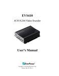
EVS200A/AW User’s Manual Copyright © EverFocus Electronics Corp, Release: Nov. 2009 Rev.A EVS200A/AW Product Name: EVS200A/AW EverFocus IP Video Encoder Model Number(s): EVS200A/AW FCC Notice "Declaration of Conformity Information" RF Declaration should be added. Please check Safety team. This equipment has been tested and found to comply with the limits for a Class A digital device, pursuant to part 15 of the FCC Rules. These limits are designed to provide reasonable protection against harmful interference in a residential Installation. This equipment generates, uses and can radiate radio frequency energy and, if not installed and used in accordance with the instructions, may cause harmful interference to radio communications. However, there is no guarantee that interference will not occur in a particular installation. If this equipment does cause harmful interference to radio or television reception, which can be determined by turning the equipment off and on, the user is encouraged to try to correct the interference by one or more of the following measures: - Reorient or relocate the receiving antenna. - Increase the separation between the equipment and receiver. - Connect the equipment into an outlet on a circuit different from that to which the receiver is connected. - Consult the dealer or an experienced radio/TV technician for help. Warning: Changes or modifications made to this equipment, not expressly approved by EverFocus or parties authorized by EverFocus could void the user's authority to operate the equipment. This device complies with part 15 of the FCC Rules. Operation is subject to the following two conditions: (1) This device may not cause harmful interference, and (2) This device must accept any interference received, including interference that may cause undesired operation. This device and its antenna(s) must not be co-located or operating in conjunction with any other antenna or transmitter. FCC Radiation Exposure Statement: This equipment complies with FCC radiation exposure limits set forth for an uncontrolled environment. This equipment should be installed and operated with minimum distance 20cm between the radiator & your body. EverFocus Electronics Corp. 12F, No. 79, Sec. 1, Shin-Tai Wu Rd., His-Chi, Taipei Hsien, Taiwan, R.O.C. 2 EVS200A/AW EVS200A/AW complies with CE and FCC. About this document All the safety and operating instructions should be read and followed before the unit is operated. This manual should be retained for future reference. The information in this manual was current when published. The manufacturer reserves the right to revise and improve its products. All specifications are therefore subject to change without notice. Safety Notice -These limits are designed to provide reasonable protection. This equipment generates, uses and can radiated radio frequency energy and, if not installed and used in accordance with the instructions, may cause harmful interference to radio communications. However, there is no guarantee that interference will not occur in a particular installation. If this equipment does cause harmful interference to radio or television reception, which can be determined by turning the equipment off and on, the user is encouraged to try to correct the interference by one or more of the following measures: -Reorient or relocate the receiving antenna. -Increase these separations between the equipment and receiver. -Connect the equipment into an outlet on a circuit different from that to which the receiver is connected. -Consult the dealer or an experienced radio/TV technician for help. The changes or modifications not expressly approved by the party responsible for compliance could void the user's authority to operate the equipment. To reduce risk of fire or electric shock, do not expose this appliance to rain or moisture. Do not attempt to disassemble the appliance. To prevent electric shock, do not remove screws or covers. There are no user-serviceable parts inside. Contact qualified service personnel for maintenance. Handle the appliance with care. Do not strike or shake, as this may damage the appliance. Do not use strong or abrasive detergents when cleaning the appliance body. Use a dry cloth to clean the appliance when it is dirty. When the dirt is hard to 3 EVS200A/AW remove, use a mild detergent and wipe gently. Do not operate the appliance beyond its specified temperature, humidity or power source ratings. Do not use the appliance in an extreme environment where high temperature or high humidity exists. Use the appliance at temperature within 0℃ ~ +40℃ / 32 ~ 104 and a humidity below 90%. The input power source for this appliance is 12 VDC & PoE. Use only the recommended power supplies. Power supplies must comply with the requirement of the latest version of IEC60950-1. Substitutions may damage the unit or cause a fire or shock hazard. Electrostatic-sensitive device. Use proper CMOS/MOSFET handing precautions to avoid electrostatic discharge. Installation should be performed by qualified service personnel only in accordance with the National Electrical Code or applicable local codes. Terms and Trademark Ethernet, Internet Explorer, Linux, Microsoft, Windows, WWW are registered trademarks of the respective holders. Other product names appearing in this User's Guide may be trademarks or registered trademarks of their respective holders. Java™ and all Java-related logos and trademarks are trademarks or registered trademarks of Sun Microsystems, Inc. in the United States and other countries. Support If the unit ever needs repair service, the customer should contact the nearest EverFocus Electronics Corp. Service Center for return authorization and shipping instruction. About AC Adaptor Specifications for AC adaptor Power Supply: 12VDC, 1 A Power Output: 12VDC, 1 A Operating Temperature: 0 ~ 40 / 32 ~ 104 External Dimensions: 56 mm x 68 mm x 101 mm / 2.24” x 2.72” x 4.04” 4 EVS200A/AW TABLE OF CONTENTS 1. INTRODUCTION....................................................................................................6 2. FEATURES ..............................................................................................................6 3. ACCESSING THE CAMERA MENU ...................................................................7 4. SETTING................................................................................................................14 4.1 SYSTEM INFO ......................................................................................................14 4.1.1 Information .................................................................................................14 4.1.2 Log ..............................................................................................................15 4.2 USER CONFIG ......................................................................................................16 4.3 NETWORK ...........................................................................................................18 4.3.1 Network.......................................................................................................18 4.3.2 DDNS..........................................................................................................20 4.3.3 Bandwidth ...................................................................................................21 4.3.4 SMTP/FTP ..................................................................................................22 4.3.5 Network Alarm (reserved for PowerCon)...................................................24 4.3.6 Wireless (For EVS200AW only).................................................................24 4.4 VIDEO .................................................................................................................26 4.4.1 Multi Streaming ..........................................................................................26 4.4.2 Video - Camera ...........................................................................................28 4.5 AUDIO .................................................................................................................29 4.6 USER .................................................................................................................30 4.7 EVENT...............................................................................................................32 4.7.1 Event ...........................................................................................................32 4.7.2 Motion.........................................................................................................35 4.7.3 Alarm...........................................................................................................36 4.7.4 Time Mask ..................................................................................................37 4.8 SYSTEM ............................................................................................................38 4.8.1 Date/Time....................................................................................................38 4.8.2 Daylight Saving ..........................................................................................40 4.8.3 SD Card.......................................................................................................41 4.8.4 Serial Communication ................................................................................43 4.8.5 Maintenance................................................................................................44 4.9 EKB200..............................................................................................................45 4.9.1 Action List...................................................................................................45 5 EVS200A/AW 1. INTRODUCTION The EVS200A/EVS200AW is a high performance, two channel solution that integrates analog cameras into an IP-based video surveillance system. The unit supports NTSC/PAL sources at up to 30fps, per channel, over IP networks and provides bidirectional audio communication in parallel with video. The EVS200A/EVS200AW also features a Dual Streaming function allows it to generate 4 independently configurable H.264, MPEG4 or MJPEG video streams (2 per input). These video signals can be received and displayed with a standard web browser or Nevio Express management software. The EVS200AW wireless model also has full support for both Wired Equivalent Privacy (WEP) and Wi-FI Protected Access (WPA/WPA2), making it one of the most secure wireless network devices on the market. The EVS200A/EVS200AW is ultra-compact, perfect for any application that depends on space-saving solutions. 2. FEATURES z High quality H.264, MPEG-4 and MJPEG multi stream output at 4CIF resolution @ 60fps z H.264/MPEG4/MJPEG dual stream output per channel for simultaneous live monitoring and high resolution recording z Smart Wizard settings for varied Event and schedule recording z z Support PTZ control Built-in SD memory card slot for local storage and support SDHC z Two-way Audio z Power over Ethernet (PoE) IEEE 802.3af. z Ultra-compact size for space-saving applications 6 EVS200A/AW 3. ACCESSING THE CAMERA MENU Step 1.Start an Internet Explorer browser. Step 2. Enter the IP address or host name of the camera in the Location/Address field of your Internet Explorer browser. (Please refer to EVS200A/AW Installation Guide for how to find the IP address) Step 3. Input “Username” and “Password”. Default Username is “user1” and default password is “11111111”. Step 4. Click “Login” button. Step 5. You might be required to download Active X, which is required to view camera video. Please click "Yes". Step 6. Congratulation!! You should be able to see the live image now. 15 ○3 7 EVS200A/AW 1. Press button to enter Nevio Express system. For more details, please refer to Nevio Express user manual. 2. Press button to display the "Live" page. Double click on the image to show a full screen display, double click again or press ESC to return normal display. 3. Press button to enter Setting page. In Setting page, there are 8 sections: [System Info], [User Config], [Network], [Video], [Audio], [User], [Event] and [System]. Please refer to “4. SETTING” for further information. 4. Press button to close the network page. 5. Video Stream Select Video Stream from CH1 Stream 1, CH2 Stream 2 and Dual CH. Please refer to “4.4.1 Multi Streaming” for further information. Note: 1. Live View in Dual CH mode, it only displays stream 1 for each channel. 2. View Size in Dual CH mode: view size is 704x480 and it is not changeable. 3. Once Dual CH is selected, the active channel will be highlighted with a red frame. Digital Zoom function is workable for both channels. However only the active channel that has a red frame highlighted can be moved to different directions through the control of arrow buttons. Highlighted red frame 8 EVS200A/AW 6. View Size You can select View size to either reduce or enlarge the image to the appropriate view size. Select the view size for live images from: NTSC: 704*480/640*480/352*240/320*240/176*120 PAL: 704*576/640*480/352*288/320*240/176*144 7. Record The record button is used to record the current video stream. The location where the image file is saved can be specified in Setting -> User’s Config. Please refer to “4.2 User Config” for further information. Note: Record segment is limited to5 min. If you need to do long time recording, please set schedule recording. For more details about schedule recording, please see “4.7 Event”. 8. Snapshot The Snapshot button saves a snapshot of the video image currently being displayed. The location where the snapshot data is saved can be specified in Setting -> User’s Config. Please refer to “4.2 User Config” for further information. 9~10. Play Audio/Transmit Audio Click the “Play Audio” and “Transmit Audio” buttons to switch the sound off and on for the speaker and microphone, respectively. 11. PTZ Control Press button to open PTZ control window. Note: When PTZ function is ON, digital zoom function will be disabled. Press button to close PTZ control window. 9 EVS200A/AW 12. PTZ Control – Navigation Mode Select this to browse in direction user pointing at. 13. PTZ Control – Click-n-Go Mode Select this and system will center the pointing location for browsing. Before Click-n-Go mode After Click-n-Go mode EVS200A/AW provides 3 methods to control PTZ: 1. Control panel 2. On Screen Control 3. PTZ Control Shortcuts. 10 EVS200A/AW ○1 Control Panel : Zoom in Focus near : Zoom out : Focus far : Iris + : Iris – Arrow buttons: Click on an arrow button to navigate in that direction. : stop current action. : User can select PTZ speed from High, Standard, Low and Minimum. Preset button: Click this button first, and input a preset position number by clicking number key and then click “Go” button to move the camera to a preset location. Note: To use this function, user need to set preset location in advance. Auto Pan button: Click this button first and input a preset auto pan No. by clicking number key (1 for AB Pan, 2 for Endless Pan) and then click “Go” button to run a preset auto pan. Note: To use this function, user need to set Auto Pan in advance. Pattern button: Click this button first and input a preset pattern No. by clicking number key (1 ~4) and then click “Go” button to run a preset Pattern. Note: 1. Click on live screen once to stop running pattern. 2. To use this function, user need to set Pattern in advance. Tour button: Click this button first and input a preset Tour No. by clicking number key and then click “Go” button to run a preset tour. Note: To use this function, user need to set tour in advance. 11 EVS200A/AW Number button, Go button and Clear button: - Click desire number button and it will show in the gray text area at lower-left corner. - Click “Clear” button to clear the text area. - Click “Go” button to run a selected function. Clear button: Click this button to clear the digit selection indicator. Menu button: Click this button to enter to OSD menu. Set button: Click this button to set preset point. Delete button: Click this button to delete preset point. ○2 On Screen Control: The whole screen is divided into 16 areas. Every area corresponds to a PTZ function, click on an area to execute the specific function of PTZ. Please see the table of the PTZ function with its mapping area number below. (Please refer to the above screenshot for the area number). 1. PTZ pan and tilt to left and up directions 2. PTZ tilt up 3. PTZ tilt up 4. PTZ pan and tilt to right and up directions 5. PTZ pan left 6. Focus Closer 7. Zoom In 8. PTZ pan right 9. PTZ pan left 10. Focus Further 11. Zoom Out 12. PTZ pan right 13. PTZ pan and tilt to left and 14. PTZ tilt down 15. PTZ tilt down down directions 16. PTZ pan and tilt to right and down directions 12 EVS200A/AW ○3 PTZ Control Shortcuts Right click the mouse to get a PTZ Control Shortcuts panel. User can control the PTZ through a PC’s keyboard. The keys in red color correspond to the same keys of keyboard. 14. Manual Control – Trigger Event Press “Trigger Event” button to trigger an event directly from live view page, and event actions will be effective if they have been set in “Event” menu. (Please refer to “4.7.1 Event”) 15. Manual Control – Reset Alarm 1 Press “Reset Alarm 1” button to reset alarm output 1 remotely. 16. Manual Control – Reset Alarm 2 Press “Reset Alarm 1” button to reset alarm output 2 remotely. 17. Status Display The name of the camera whose settings currently being configured, current date/time and current frame rate will be displayed. 18. Event signals Alarm 1 Alarm 2 Motion When an alarm or motion event is triggered, a signal icon will flash to alert user. The first icon is for alarm event and rest of the 5 icons are for motion event. The motion event icons which differed by colors correspond to the motion trigger areas you have set in Motion menu. Please refer to “4.7.2 Motion” for detailed information about Motion setup. 13 EVS200A/AW 4. SETTING Click “Setting” button to enter the setting menu. There are 9 sections in setup menu: [System Info], [User Config], [Network], [Video], [Audio], [User], [Event], [System] and [EKB200]. 4.1 System Info System information and system log check of the setup menu can be performed on this page. The “System Info” page has 2 tabs: [Information] tab and the [Log] tab. 4.1.1 Information System Information: Firmware version, MAC address, Video Type, Model number. (unchangeable, for reference only) 14 EVS200A/AW 4.1.2 Log System Log: Date/Time: displaying date and time of the log. Log message: all information and event message, including login, user’s IP, reboot, firmware upgrade, load factory default, configuration reset and event detected. System will keep the newest 256 records. 15 EVS200A/AW Press button to export system log into “.txt” file and select the location where the exported log file will be saved to. 4.2 User Config Live view configuration is to be set by user. Each login user can make his/her own settings for the following items: Text Setting Check the box for text of Machine name, Date/Time or Frame Rate to be displayed on the screen. Foreground Color: Select the foreground color of text to be displayed by moving the slide bar between Red, Green and Blue until your desire color is obtained. Position: Select the position where the text will be displaying from Upper Left / Lower Right / Lower Left. Press Apply to apply the setting changes or Reset to reset without saving the change. 16 EVS200A/AW Date/Time Format Used in Text Date Format: Select Date/Time Format from the following options: Time Format: 24 Hours or 12 Hours. Press Apply to apply the setting changes or Reset to reset without saving the change. Recording/Snapshot Export Setting Enable Event Recording to PC: Allow event video recorded to users' PC if any events have been set to record to PC. Export folder: Select Export folder by clicking on folder to be exported. button, then direct to the File size: Able to limit the size of the single recording file in minutes. When the single recording file size exceeds the time you set, system will create a new file to continue recording. Overwrite: Select “ON” for overwriting recording/snapshot file when the disk storage capacity is full. If the remaining hard disk capacity is less than ____ MB (enter the value you wish to set between 50~2000), system will stop recording or start overwriting. Press Apply to apply the setting changes or Reset to reset without saving the change. Language Setting Language: Select the language to be displayed in web page. Default language is English. To remove a language, press Remove button. To add a new language which is not listed in the original configuration, press the Browse button to locate 17 EVS200A/AW the new language file (.evb) and then click the Upload button. Note: Upload a new language file will reboot system automatically. Please reconnect video encoder after reboot. Press Apply to apply the setting changes or Reset to reset without saving the change. 4.3 Network The network settings and the settings relating to Network, DDNS, Bandwidth, SMTP/FTP and Network Alarm can be configured on this page. The "Network setup" page has 5 tabs of the [Network] tab, the [DDNS] tab, the [SMTP/FTP] tab and the [Network Alarm] tab. 4.3.1 Network The following information is required to configure the network settings. Contact the network administrator or your Internet service provider. • IP Type • IP address • Subnet mask • Gateway (when using the gateway server/router) 18 EVS200A/AW • Primary DNS, Secondary DNS (when using DNS) IP Setting IP Type: DHCP: Configure the DHCP server not to assign the same IP addresses used for the other network cameras and PCs whose IP address is unique. Refer to the network administrator for the settings of the server. Default: DHCP. Static IP: User can manually set the static IP for network connection. PPPoE: This is a DSL connection application, ISP will ask user to input user name and password. Note: If PPPoE is used as IP type, IP Utility software will not be able to detect the device. IP address: When not using DHCP, enter the IP address of the camera. Do not enter the IP address already used for PC or other network cameras. Subnet Mask: This field is to set the netmask for your network so as the IP camera will be recognized within the network. Example: 255.255.255.000. When DHCP is selected, the DHCP server will assign this value automatically. Gateway: This field is to set the gateway for your network so the IP camera will be recognized within the network. When DHCP is selected, the DHCP server will assign this value automatically. Primary DNS: An IP address of DNS server that is provided by ISP. Secondary DNS: If your ISP provides you an IP address secondary DNS, please set it here. 19 EVS200A/AW Username: Enter User name of the account (used only for PPPoE). Password: Enter Password of the account (used only for PPPoE). Press Apply to apply the setting changes or Reset to reset without saving the change. Port Setting HTTP Port: Port number for HTTP/WEB communication. Press Apply to apply the setting changes or Reset to reset without saving the change. 4.3.2 DDNS DDNS setting When accessing the camera via the Internet from the network environment of which the global IP address is obtained using DHCP, the DDNS function is 20 EVS200A/AW necessary. To use the DDNS function, it is necessary to connect to the dedicated DDNS server. We offer 4 DDNS server providers as follow: ○ ○ ○ ○ www.everfocusddns.com www.sitelutions.com www.dyndns.com www.no-ip.com Enable: Check the box to enable DDNS setting. Service ISP: If you choose EverFocus DDNS server, you can obtain a free account name from EverFocus ”www.everfocusddns.com”. .everfocusddns.com Enter an IP Cam Account Name: Press button to register or update DDNS account. If you wish to get a domain name from other DDNS provider, it is necessary to configure Record ID, FQDN, Username and password and register in DDNS server. Refer to the web site for further information about the DDNS. Press Apply to apply the setting changes or Reset to reset without saving the change. 4.3.3 Bandwidth 21 EVS200A/AW Bandwidth Setting Max. Bandwidth: Specify, Unlimited / 64 K/ 128 K/ 256 K / 512 K / 1M / 2M / 4M / 8M bps. the maximum bandwidth that the camera is allowed to use on the network. This is a useful function when connecting the camera to busy or heavily loaded networks. The default setting is Unlimited. Max. Client Limit: enter a value here to restrict the number of clients accessing the camera. This is useful if you need to save on bandwidth. Up to 32 clients is allowed to see live video simultaneously. Subsequent viewers will see a blank image. Press Apply to apply the setting changes or Reset to reset without saving the change. Note: Due to the dual channel configuration, access of one user will occupy capacity of 2 clients. 4.3.4 SMTP/FTP Set SMTP The settings relating to the mail server used to send the e-mail notification from the camera to predefined addresses via SMTP can be configured. SMTP Server: Enter the IP address or the host name of the SMTP server used to 22 EVS200A/AW send e-mails. SMTP Port: Enter the port number for SMTP. Default is 25. Authentication: Check the box, if the SMTP server requires Authentication (user/ password). User name: Input the login user ID if the SMTP server requires Authentication. Password: Input the password if the SMTP server requires authentication. Receiver Address: Input the e-mail address for receiving e-mail message when the EVENT is enabled and triggered. Please use “;” to separate address. Sender Address: Input sender’s e-mail address, so that receiver can recognize the sender when an event message is sent out. Send Test Mail: Press address. button to send a testing mail to the assigned Set FTP The settings relating to the FTP server used to transmit the alarm images can be configured. FTP Server: Enter the IP address or the host name of the FTP server. FTP Port: Enter the port number for FTP server. Default is 21. Recording Path: Assign the recording path. User Name: Set FTP User’s name. Password: Set FTP password. PASV mode: Check to enable Passive mode, normally enable Passive mode. When failed to establish the connection, uncheck "PASV" mode. Test FTP Server: Press FTP server. button to send a testing file to the assigned Press Apply to apply the setting changes or Reset to reset without saving the change. 23 EVS200A/AW 4.3.5 Network Alarm (reserved for PowerCon) Set Network Alarm This function is reserved for PowerCon software, for the detail setting please refer to PowerCon network alarm protocol. 4.3.6 Wireless (For EVS200AW only) 24 EVS200A/AW Wireless Setting Enable Wireless (Default: disable) SSID: Name of the wireless network the camera is configured for. The field accepts up to 32 alphanumeric characters. The name must be exactly the same as the one used in the wireless access point or the connection will not be established. Network Type: Infrastructure or Ad-Hoc (Default: Infrastructure) -“Infrastructure” makes the Network Camera connect to the WLAN via an Access Point. -“Ad-Hoc” makes the Network Camera connect directly to a host equipped with a wireless adapter in a peer-to-peer environment. Channel: Shows the wireless channel currently in use. (Default: 1) Disable Security: Check the box to disable Security When selecting WEP: WEP (Wired Equivalent Protection) key should follow either one of the following rules: - As 5 characters for 64-bit WEP and 13 characters for 128-bit WEP. - As 10 hexadecimal (0-9, A-F) characters for 64-bit WEP and 26 hexadecimal (0-9, A-F) characters for 128-bit WEP. ) Authentication: Open or Shared (Default: Open) “Open” – communicates the key across the network. “Shared” – allows communication only with other devices with identical WEP settings. Key Length: 64 or 128 bits (Default: 64 bits) Key Format: HEX or ASCII (Default: HEX) Network Key: Entering a key in either hexadecimal or ASCII format. Confirm Key: Double confirm network key. When selecting WPA-PSK/WPA2-PSK: WPA (Wi-Fi Protected Access) key should follow either one of the following rules: - As 64 hexadecimal (0-9, A-F) characters. - As 8 to 63 ASCII characters. Authentication: AES or TKIP (Default: AES) Network Key: Entering a key in either hexadecimal or ASCII format. 25 EVS200A/AW Confirm Key: Double confirm network key. IP Status: Show IP status when wireless connection, including IP Type, IP Address, Subnet mask, Gateway, Primary DNS, Secondary DNS. Press Apply to apply the setting changes or Reset to reset without saving the change. 4.4 Video The settings relating video such as streaming, camera OSD can be configured on this page. The "Video" page has 2 tabs: the [Multi-streaming] tab and the [Camera] tab. 4.4.1 Multi Streaming Channel 1/2 Stream Setting The system can output 4 video streams simultaneously. For each of them, user can set compression format, resolution, quality and frame rate individually. Stream 1 is always enabled for live view. Check “Enable” box to enable other streams. Format: Select encode format from H.264, MPEG4 and MJPEG. 26 EVS200A/AW Resolution: NTSC: 4CIF (704*480) / VGA (640*480) / CIF (352*240) PAL: 4CIF (704*576) / VGA (640*480) / CIF (352*288) Quality: there are 8 types of quality, please choose from Highest / Higher / High / Middle / Normal / Low / Lower / Lowest. Frame Rate: select from NTSC: 1 / 3 / 5 / 15 / 30 fps, PAL: 1/ 2.5/5/12.5/25 fps Note: 1. The stream 1 for each channel allows D1, Half-D1, and CIF. The stream 2 of each channel allows CIF and QCIF resolution. Basically stream 1 is for storing and stream 2 requires smaller bandwidth which is good for transmission. 2. Total frame rate cannot exceed 60 fps. 3. System performance may be influenced if user enables 4 video streams simultaneously. Press Apply to apply the setting changes or Reset to reset without saving the change. Video Recording Setting User can set video recording by selecting one of the enabled video streamings. This will allow user to view live images as well as to record video of the other video streaming. Channel 1/2: Select video recording stream from any enabled stream. Video File format: Recording file will be saved as AVI or ARV, select which file format to be used. Press Apply to apply the setting changes or Reset to reset without saving the change. 27 EVS200A/AW 4.4.2 Video - Camera Channel: add channel selection. Camera Settings Channel title: add channel title. PTZ function: select PTZ function ON or OFF ID: This entry is used to assign the own ID code of channel 1 camera. Protocol: Select protocol from Everfocus, Pelco-D, Pelco-P, Samsung and Panasonic. (Default: Pelco-D) Press Apply to apply the setting changes or Reset to reset without saving the change. Image Settings Brightness: to increase or decrease object brightness of images. It is adjustable from 0~100. Contrast: to increase or decrease object contrast of images. It is adjustable from 0~100. Hue: to increase or decrease hue of video images. It is adjustable from 0~100. 28 EVS200A/AW Whenever the above three picture parameters are adjusted, the values will be set to the channel automatically. Press Apply to apply the setting changes or Reset to reset without saving the change. 4.5 Audio The EVS200A/AW video encoder can transmit audio to other clients using a built-in microphone or connecting to external microphone to play audio received from other clients via connected speakers. This section describes how to configure the basic audio settings. Audio Check Enable Audio box to enable audio function. Audio Input: Audio from an internal microphone or a line source can be connected to the Audio connector of EVS200A/AW. The audio source can be selected from Internal Microphone, External Audio Input L and External Audio Input R. 29 EVS200A/AW Audio Input volume: Adjust the Audio Input Volume for the audio input devices connected to the camera if there are problems with the sound input being too low or high. Press Apply to apply the setting changes or Reset to reset without saving the change. 4.6 USER User Information Maximum 10 users can be set for using the IP camera. The user information displays the authorized users and access levels: • Supervisor/Administrator –a supervisor/administrator has unrestricted access to the Setting menu and can determine the registration of all other users. However, administrator is not allowed to change supervisor’s account and password. • User- a user can view the Live View page, system info, network, video, audio, and adjust user config settings. The user does not have access to the “user”, “event” and “system pages”. 30 EVS200A/AW • Guest- the lowest level of access, which only allows the user access to the Live View page. Note: Please select Active in Status section to activate user account. Press Apply to apply the setting changes or Reset to reset without saving the change. Please see below the table of user’s right: User Admin User Guest Nevio Express x x Live x x Setting x x (limited) Exit x x x Video Stream x x x View Size x x x Digital Zoom x x Record x x Snapshot x x Audio In x x Audio Out x x PTZ control x x Manual control x Right 31 x EVS200A/AW 4.7 EVENT An event in the camera is when an Event Type is activated and causes certain actions to be performed. The event type is the set of conditions that specifies how and when which actions will be performed. This table describes how to setup action types and event type. Event Action Alarm Motion Input Manual Detection 1&2 Trigger 1&2 Schedule Pre/Post Video Loss Recording -Alarm Action Settings Trigger Contact Type: N.O./N.C. Alarm Duration Time: output 1&2 x x x 5sec~5min x Attached I-frame.jpg or Send Mail notification x x x Upload to FTP x x x x (pre-alarm) Record to PC* x -- x -- x x x x (pre-alarm) Network Alarm attach Video file's. x x Video File Format: x x x x I-frame.jpg Re-trigger Alarm -- x Note: 1. * Record to PC only works when PC and IP camera are connected. 2. **Either Upload to FTP or Record to Network Storage can be selected to record event video to remote site. 3. Up to 10 event types can be configured in the camera, and up to 3 of these can be configured to upload images. 4.7.1 Event The settings relating to event occurrences such as settings for the event occurrence, motion, alarm and time mask can be configured on this page. The "Event" page has 4 tabs: [Event] tab, the [Motion] tab, the [Alarm] tab and the [Time Mask] tab. 32 EVS200A/AW button to add an event condition. Press To modify the event list, click on the event and it will be highlighted. Press button to modify the setting. To remove an event from event list, click on the event and it will be highlighted. Press button to remove the event. Check Enable checkbox to activate event actions when the event occurs in the specified time zone. To change the priority of events, click on the event and it will be highlighted. Press or button to move between events. The event that has highest priority will be activated first. Press Apply to apply the setting changes or Reset to reset without saving the change. The following example describes how to set the camera to upload images to FTP when someone presses Manual trigger button: 33 EVS200A/AW 1. Click button in Event page. 2. Enter an event name for the event, e.g. Event 1 3. Select “Manual Trigger” as event type. 4. Select “Upload to FTP” as action type. 5. Check “Enable Pre-alarm Buffer” and “Enable Post-alarm Buffer”. For pre-and post alarm buffer setting, please refer to “4.7.3 Alarm”. 6. Check “Enable This Event”. 7. Select “Always” for time mask. For detail about Time Mask, please refer to “4.7.4 Time Mask”. 8. Record Channel: Select which channel to be recorded when event occurs. It is selectable from Channel 1 and Channel 2. 9. Click settings. to save this event in event list, or 34 to cancel the EVS200A/AW 4.7.2 Motion Motion Detection First, select the channel for motion detection setting. User can define the motion area to be detected by left clicking the mouse to draw lines. Every click is an end point of the line. When the detection area is formed, double click the mouse to have all the lines connected. To remove the selection, simply right click the mouse, the selected polygon will be deleted. Press to update the current image. Press to have the entire screen selected for motion detection. Press to clear all selections. Press and click on the polygon, to erase that polygon. There are 5 motion trigger areas, which can be distinguished by 5 different colors. Check Enable checkbox to enable event action. For each of them, you can set the event action to be activated. Event action can be set in “Event” section. Moreover, you can set the Sensitivity level for motion triggered by selecting from 1 (low), 2, 3, 4, 5, 6, 7, 8, 9 to 10 (high). 35 EVS200A/AW 4.7.3 Alarm Alarm Output Setting Contact Type: Normal Close, Normal Open Duration Time: Select duration time of alarm output from 5 sec, 10 sec, 20 sec, 30 sec, 60 sec, 2 min, 3 min and 5 min. Press Apply to apply the setting changes or Reset to reset without saving the change. Pre/Post Alarm Setting This function is used to check what happened immediately before and after a trigger, e.g. 5 seconds before or after a motion has been detected. Pre-Alarm Buffer: Image saved internally in the server from the time immediately preceding the trigger. Input the desired length of pre-trigger buffer time. It can be set up to 120 seconds. Post-Alarm Buffer: Image saved internally in the server from the time immediately after the trigger. Input the desired length of post-trigger buffer time. It can be set up to 120 seconds. Press Apply to apply the setting changes or Reset to reset without saving the change. 36 EVS200A/AW Re-trigger Filter Setting Re-trigger Filter: Set a re-trigger filter time, if another event is triggered during this time, this triggered event will be ignored. Press Apply to apply the setting changes or Reset to reset without saving the change. 4.7.4 Time Mask Time Mask Setting Time mask setting allows you to schedule event actions. Select Always for event action to be taken continuously. Press button to add new time period. Mask Name: Input a mask name for the new time period. Tick the checkbox for the day to be scheduled: Sun, Mon, Tue, Wed, Thu, Fri & Sat. Set the Start Time and End Time for time mask by clicking Up arrow or Down arrow. Or simply press Press for a full day of event action. button to remove a scheduled time period. 37 EVS200A/AW An example on how to set weekend as time mask: 1. 2. Click from time mask setting. Enter Mask name, e.g. Weekend. 3. 4. Check “Sun” & “Sat” boxes. Select “Start time” and “End time” or “Full day”. Press Apply to apply the setting changes or Reset to reset without saving the change. 4.8 SYSTEM Date/Time, Daylight Saving, SD card and Maintenance settings can be performed on this page. The "System" page has 4 tabs of the [Date/Time] tab, the [Daylight Saving] tab, the [SD card] tab and the [Maintenance] tab. 4.8.1 Date/Time Machine Name Setting Machine Name: Enter the name of the camera. The entered name will be displayed in the status display area. 38 EVS200A/AW Press Apply to apply the setting changes or Reset to reset without saving the change. Set Time Zone Time Zone: Select a time zone according to the location where the camera is in use. Press Apply to apply the setting changes or Reset to reset without saving the change. Set Date/Time Manually Date: Click the calendar and pick the date. Press << to go previous year, < to go previous month, > to go next month and >> to go next year. Time: Click on Hour, Minute, Seconds, am/pm; then use up arrow to increase value and down arrow to decrease value. Press Apply to apply the setting changes or Reset to reset without saving the change. Set Date/Time Sync. Tick Enable NTP checkbox to enable NTP server. NTP server: Time automatically adjusted by synchronizing with NTP server will be used as the standard time of the camera. Sync. Internal: Select an interval (1 - 24 hours: in 1 hour intervals) of synchronization with the NTP server. 39 EVS200A/AW Press Apply to apply the setting changes or Reset to reset without saving the change. 4.8.2 Daylight Saving Set Daylight Saving Tick Enable Daylight Saving checkbox to enable daylight saving. Set the start time to daylight saving time. Set the start week of daylight saving time: 1st / 2nd / 3rd / 4th / Last Set the start date of daylight saving time: Sunday / Monday / Tuesday / Wednesday / Thursday / Friday / Saturday Set the start month of daylight saving time: January / February / March / April / May / June / July / August / September / October / November / December. Set the starting time change of daylight saving time: Choose the “From” time and “End” time when daylight saving starts. Set the end time of daylight saving time. Set the end week of daylight saving time: 1st / 2nd / 3rd / 4th / Last Set the end date of daylight saving time: Sunday / Monday / Tuesday / Wednesday / Thursday / Friday / Saturday Set the end month of daylight saving time: January / February / March / April / 40 EVS200A/AW May / June / July / August / September / October / November / December. Set the ending time change of daylight saving time: Choose the “From” time and “End” time when daylight saving ends. Press Apply to apply the setting changes or Reset to reset without saving the change. 4.8.3 SD Card Setup SD Card Notification: Notification will be made via e-mail when the remaining space of the SD memory card reached the value selected from the following. 50%, 20%, 10%, 5%, 2%, 0% Notes: 1. When "50%" is selected, e-mail notification will be made each time the remaining space reaches 50%, 20%, 10%, 5%, 2% and 0%. 2. E-mail notification may not always be made at a very moment when the remaining space of the SD memory card reached the selected value. Event Recording: FTP backup only: Event video will record to SD card when network is 41 EVS200A/AW disconnected. Normal: Follow the event actions settings you have made in “Event” menu to record event video to SD card. Overwrite: Select ON for overwriting data when SD card memory is full. Select OFF for not overwriting SD card data. Press Apply to apply the setting changes or Reset to reset without saving the change. SD Card Utility Before formatting the SD memory card, it is necessary to press Once button is pressed, button. button will be shown for user to insert the SD card back. Press button to format SD card. Obtain images on the SD memory card 1. Access the camera using the Windows command prompt or FTP client software. → The window with the user name and password entry fields will be displayed. 2. Enter the user name whose access level is "1. Administrator" and its password. → Log in the camera. 3. A directory of all saved data will be displayed. You are now ready to obtain images from SD card. Note: 1. It is impossible to access the SD memory card in the process of formatting. 2. All data saved on the SD memory card will be deleted when the SD memory card is formatted. 3. Do not turn the power of the camera off in the process of formatting. 42 EVS200A/AW 4.8.4 Serial Communication RS485 Setting Baud Rate: This field is to set the speed at which is used to transmit instruction or information through the RS485 port on the camera. There are six different speeds, 2400/4800/9600/19200/38400/57600. (Default: 9600) Data Bit: This field is the data bit at which you will be transferring. There are two settings for this option: 8 or 7. (Default: 8) Stop Bit: This field is to set the stop bit for the RS485 connection. There are two different stop bits, 1 or 2. (Default: 1) Parity: This field is to select the parity level at which you will be connected. You can choose between None, Odd, or Even parity levels. (Default: none) Press Apply to apply the setting changes or Reset to reset without saving the change. 43 EVS200A/AW 4.8.5 Maintenance Maintenance Server Reboot: The unit is rebooted without changing any of the settings. Use this method by pressing Reboot button if the unit is not behaving as expected. Restore: The unit is restarted and most current settings are reset to the factory default values by pressing Restore button. The only settings saved are: • • IP setting DDNS setting Default: The Default button should be used with caution. Pressing this button will return all of the camera's settings, including the IP address, to the factory default values. The camera will then have to be re-installed. Save/Load Configuration Server To take a backup of all of the configurations, press Save to save all configurations to a config. file. If necessary, it is then possible to return to the previous settings if the settings are changed and there is unexpected behavior. Press Browse button to locate the saved config. file (see above) and then click Load button. The settings will be restored to the previous configuration. 44 EVS200A/AW Upgrade Firmware Upgrade the EVS200A/AW with the latest firmware. Press Browse button to search firmware file. Press Upgrade button to upgrade the firmware. Note: 1. Do not disconnect power to the unit during the upgrade. The unit reboots automatically after the upgrade has completed. (1-5 minutes.) 2. During upgrading process, all event recording actions will be stopped. It will continue to record after the camera is rebooted. 4.9 EKB200 4.9.1 Action List EKB200 Button Mapping EKB-200 is an IP surveillance keyboard controller powered by USB port. User needs to set related control for each EKB-200 key in this window. In Action list window, there are 12 EKB-200 button mapping options (From Key No.1 45 EVS200A/AW to Key No.12) can be set. User can choose action and set value for each Key No. If the command requires a value, such as GoTo Preset [x] or Tour [x], user needs to enter the number [x] in the field "Value". Otherwise, the value option will be disabled. After completing setting, press “Apply” to save the changes. Then user can use these keys and joystick on EKB200 to control these actions. Key No. 13 to Key No. 16 are system preset buttons also allowing user to do operations, such as IRIS+, IRIS-, Focus Near and Focus Far. Press Apply to apply the setting changes or Reset to reset without saving the change. 46 EVS200A/AW Joystick IRIS- FOCUS NEAR IRIS+ FOCUS FAR ○3 ○4 EKB200 Panel There are 20 available Action options, including: 1. Set Preset: When the action of a key is set “Set Preset”, use joystick to select a position and press this key on KEB200 to save the position as Preset Point. 2. Goto Preset: When the action of a key is set “Goto Preset”, press this key on KEB200 and the system will go the Preset Point. 3. Goto Home: When the action of a key is set “Goto Home”, press this key on KEB200 and the system will go the Preset position. 4. Clear Preset: When the action of a key is set “Clear Preset”, press this key on KEB200 to clear the Preset Point. 5. Focus Near: When the action of a key is set “Focus Near”, press this key on KEB200 to do focus near. 6. Focus Far: When the action of a key is set “Focus Far”, press this key on KEB200 to do focus far. 7. Iris Open: When the action of a key is set “Iris Open”, press this key on KEB200 to do Iris open. 8. Iris Close: When the action of a key is set “Iris Close”, press this key on KEB200 to do Iris close. 9. Run Autopan: When the action of a key is set “Autopan”, press this key on 47 EVS200A/AW KEB200 to start autopan. 10. Stop Autopan: When the action of a key is set “Stop Autopan”, press this key on KEB200 to stop autopan. 11. OSD Menu On: When the action of a key is set “OSD Menu On”, press this key on KEB200 to display OSD Menu on the screen. 12. OSD Menu Cancel: When the action of a key is set “OSD Menu Cancel”, press this key on KEB200 to hide OSD Menu on the screen. 13. OSD Menu Enter: When the action of a key is set “OSD Menu Enter”, press this key to enter the submenu of an option of OSD menu, only if this option has a <┘ mark right next to it. 14. Tour Run: When the action of a key is set “Tour Run” and the value of the key is set to a preset tour number, press this key on KEB200 to run this preset tour. 15. Tour Stop: When the action of a key is set “Tour Stop”, press this key on KEB200 to stop running a tour. 16. Pattern Run: When the action of a key is set “Tour Run” and the value of the key is set to a preset pattern number, press this key on KEB200 to run this preset pattern. 17. Pattern Stop: When the action of a key is set “Pattern Stop”, press this key on KEB200 to stop running a pattern. 18. Set Auto Tracking: When the action of a key is set “Auto Tracking”, press this key on KEB200 to switch auto-tracking on/off. 19. Toggle Fullscreen: When the action of a key is set “Toggle Fullscreen”, press this key on KEB200 to switch screen to current size/fullscreen. 20. Select Tracking Object: When the action of a key is set “Select Tracking Object”, user can set select tracking object firstly press this key on KEB200. An icon will display on the screen. Use joystick to select desired object and press this key again save the selected object. 48 EVS200A/AW 5. SPECIFICATIONS VIDEO STREAMING Video Compression Video Resolution Video Quality Frame Rate Video Source AUDIO Compression Method Operation Mode H.264/MPEG-4/M-JPEG 4CIF, VGA, CIF, QVGA, QCIF 8 levels adjustable Up to 30fps 2 BNC composite, 1 V p-p / 75Ω NTSC/PAL auto-sense IMA ADPCM (Pulse Code Modulation) 2 way audio NETWORK Interface Supported Protocols Bandwidth Control Max. Client Limit 10Base-T/100Base-TX auto-negotiation, RJ-45 socket Support MDI/MDI-X auto crossover function HTTP, TCP / IP, UDP, RTP, RTSP, FTP, SMTP, DHCP, DNS, DDNS, NTP Min. 64 kbps adjustable 32 simultaneous clients WIRELESS (EVS200AW) Standard IEEE 802.11b/g Antenna gain 2 dBi ALARM Alarm Input/Output 2/2 EVENT MANAGEMENT Event Triggered Notification Pre- and Post- Alarm Buffer Alarm input, Manual trigger, Motion detection and Schedule recording Trigger alarm output, Send mail notification, Upload video to FTP, Record video to SD card, Record video to PC and Network alarm 48MB RAM reserved for pre-alarm record up to 120 sec LOCAL STORAGE SD Card POWER Power Supply Power over Ethernet Power Consumption PHYSICAL Weight Dimensions Secure Disk physical layer specification version 2.0 Supports SDHC Host Specification 12 VDC Yes (PoE 802.3af) EVS200A: 4.5W max. (12VDC) EVS200AW: 6W max. (12VDC) 300g / 0.66lbs 77 (W) x 38 (H) x 117 (D) mm / 3” (W) x 1.5” (H) x 4.6” (D) With Antenna: 77 (W) x 102 (H) x 153 (D) mm / 3” (W) x 4” (H) x 6” (D) 49 EVS200A/AW ENVIRONMENTAL Operating Temp. 0°C ~40°C / 32°F~104°F Humidity (20%~80% Humidity) 50 EVS200A/AW EverFocus Electronics Corp. Head Office: 12F, No.79 Sec. 1 Shin-Tai Wu Road, China Office: Room B-05D-1, KESHI PLAZA, Shangdi Hsi-Chi, Taipei, Taiwan TEL: 886-2-26982334 FAX: 886-2-26982380 www.everfocus.com.tw Information Industry Base,Haidian District, Beijing China 100085 TEL: +86-10-62973336/37/38/39 FAX: +86-10-62971423 www.everfocus.com.cn USA Office: 1801 Highland Ave. Unit A Duarte, CA 91010, U.S.A. Europe Office: Albert-Einstein-Strasse 1 D-46446 Emmerich, Germany TEL: 49-2822-9394-0 FAX: 49-2822-939495 TEL: +1-626-844-8888 FAX: +1-626-844-8838 www.everfocus.com USA N.Y. Office: 415 Oser Avenue Unit S Hauppauge, NY 11788 Tel: 631-436-5070 www.everfocus.de FAX: 631-436-5027 www.everfocus.com 2-6 Nakase.Mihama-ku. Chiba city 261-7118, Japan TEL: 81-43-212-8188 FAX: 81-43-297-0081 www.everfocus.co.jp Your EverFocus product is designed and manufactured with high quality materials and components which can be recycled and reused. This symbol means that electrical and electronic equipment, at their end-of-life, should be disposed of separately from your household waste. Please, dispose of this equipment at your local community waste collection/recycling centre. In the European Union there are separate collection systems for used electrical and electronic product. Please, help us to conserve the environment we live in! Japan Office: 1809 WBG Maribu East 18F, Ihr EverFocus Produkt wurde entwickelt und hergestellt mit qualitativ hochwertigen Materialien und Komponenten, die recycelt und wieder verwendet werden können. Dieses Symbol bedeutet, dass elektrische und elektronische Geräte am Ende ihrer Nutzungsdauer vom Hausmüll getrennt entsorgt werden sollen. Bitte entsorgen Sie dieses Gerät bei Ihrer örtlichen kommunalen Sammelstelle oder im Recycling Centre. Helfen Sie uns bitte, die Umwelt zu erhalten, in der wir leben! 51 ® EverFocus