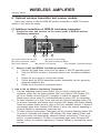
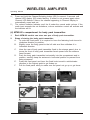
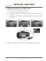
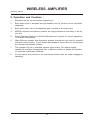
1
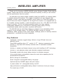
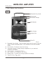
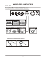
MA-808
Electronics Co., Ltd.
Head office: 814, Pei-Kang Road, Chiayi, 60096, Taiwan.
Taipei office: 5, Lane 118, Sung-teh Road, 10075, Taipei, Taiwan.
Web-http: //www.mipro.com.tw
E-mail: [email protected]
2 CE2 7 0
C
IMPORTANT SAFETY INSTRUCTION
1.
2.
3.
4.
5.
6.
7.
8.
9.
10.
11.
12.
13.
14.
15.
16.
17.
18.
Read these instructions.
Keep these instructions.
Heed all warnings.
Follow all instructions.
Do not use this apparatus near water.
Clean only with a dry cloth.
Do not block any ventilation openings. Install in accordance with the manufacturer's instructions.
Do not install near any heat sources such as radiators, heat registers, stoves, or other apparatus
(including amplifiers) that produce heat.
Do not defeat the safety purpose of the polarized or ground plug: A polarized plug has two blades with
one wider than the other. The wide blade is provided for your safety. When the provided plug does
not fit into your outlet, consult an electrician for replacement of the obsolete outlet.
Protect the power cord from being walked on or pinched particularly at plug, convenience receptacles,
and the point where they exit from the apparatus.
Only use attachments/accessories specified by the manufacturer.
Use only with a cart, stand, tripod, bracket, or table specified by the
manufacturer, or sold with the apparatus. When a cart is used, use
caution when moving the cart/apparatus combination to avoid injury
from tip-over.
Unplug this apparatus during lighting storms or when unused for long
periods of time.
Refer all servicing to qualified service personnel. Servicing is required
when the apparatus has been damaged in any way, such as power-supply
cord or plug is damaged, liquid has been spilled or objects have fallen into
the apparatus, the apparatus has been exposed to rain or moisture, does not
operate normally, or has been dropped.
To Reduce The Risk Of Fire Or Electric Shock, Do Not Expose This Apparatus To Rain Or Moisture.
Apparatus shall not be exposed to dripping or splashing and no objects filled with liquids, shall not be
placed on the apparatus.
Only used with the battery which specified by manufacturer.
The power supply cord set is to be the mains disconnected device.
WARNING
1.
2.
3.
FOR OUTDOOR USE:
TO REDUCE THE RISK OF FIRE OR ELECTRIC SHOCK, DO NOT EXPOSE THIS APPARATUS TO
RAIN OR MOISTURE.
UNDER WET LOCATION:
Apparatus shall not be exposed to dripping or splashing and no objects filled with liquids, such as
vases, shall not be placed on the apparatus.
SERVICE INSTRUCTIONS:
CAUTION - These servicing instructions are for use by qualified service personnel only. To reduce the
risk of electric shock, do not perform any servicing other than that contained in the operating
instructions unless you are qualified to do so.
This symbol indicates that dangerous voltage constituting a risk of electric shock is present
within this unit.
This symbol indicates that there are important operating and maintenance instructions in the
literature accompanying this unit.
Disposal
Dispose the unusable device according to valid regulations.
Disposal of spent batteries/accumulators
You are required by law to return all spent batteries. Disposing of used batteries
with domestic waste is prohibited!
Batteries / NiCad cells containing toxins are marked by accompanying
symbols that refer to the prohibition of disposal with domestic waste.
The designations for the decisive heavy metals are: Cd=cadmium,
Hg=mercury, Pb=lead. You may return spent batteries/accumulators
free of charge to the recycling centres, our outlets or anywhere else
where batteries/accumulators are sold.
2005-08-13
By doing so, you fulfil the legal requirements and contribute to the conservation of
our environment!
The term "IC:" before the radio certification number only signifies that Industry
Canada Technical specifications were met.
Operation is subject to the following two conditions: (1) this device may not cause
interference, and (2) this device must accept any interference, including interference
that may cause undesired operation of the device.
Contents
Operating Manual
Operation of Wireless Amplifier System
1. Parts Names And Functions
2-3
2. Control Panel
4
3. Operation of Transmitters Storage
6
4. Replacing Batteries
7
5. Selection and installation of wireless receiver modules:
9
6. Optional wireless transmitter and receiver module:
12
7. Additional Installation of CDM-3 Player:
15
8. Operation and Cautions :
16
9. Specifications :
16
Accessories for Hand Held Microphone
1. Parts Names And Functions
17
2. Battery Insertion
18
3. Operating Instructions
18
4. Cautions
18
Accessories for Body Pack Transmitter
1. Parts Names And Functions
2. Operating Instructions
19-20
3. AF 4-pin Input Connection Method
21
4. Battery Installation
22
5. Cautions
23
20
-0-
WIRELESS AMPLIFIER
Operating Manual
Thank you for choosing a MIPRO MA-808 series Wireless Portable Public Address
System. Please take time to read these instructions carefully so that you can achieve
the best performance from the system.
The MA-808 is the latest wireless amplifier model from MIPRO, an industry leader
in portable wireless PA systems. This rugged, bi-amplified unit was designed with
versatility in mind. It has clear and powerful sound, thanks to a Class AB amplifier for
the HF driver and Class D amplifier for the large10-inch woofer. It is equipped with up
to 2 wireless receiver modules, 1 wired microphone and a 3-in-1 CD, MP3 and FLASH
player & recorder. This AC and battery-powered system has large capacity
rechargeable batteries and a universal AC switching power supply, ensuring
uninterrupted quality audio any place, anywhere and anytime.
The MA-808 can be used either indoors or outdoors at any demanding venue,
making it a truly portable system. The MIPRO MA-808 is perfect for schools,
institutions, rallies, sporting events, trade shows, weddings, places of worship, business
presentations - practically any event imaginable.
Key Features:
!
!
!
!
!
!
!
!
!
!
!
!
!
Lightweight, extremely rugged design delivers a huge 250-watt clear and
powerful sound.
Class-D/AB amplifiers drive 10
woofer & 1.5
titanium compression driver.
Industry s only dual UHF diversity receivers with 16 automatic scanable
frequencies.
Industry
s easiest and fastest channel set-up with AutoScan & ACT technology.
Industry
s only adjustors detect and eliminate unwanted interference.
Retractable handle with sturdy bottom wheels for effortless transport.
Voice priority feature automatically lowers the music when speaking into the
wireless/wired microphone.
Built-in storage for transmitters.
Smart 4-segment rechargeable battery fuel gauge.
Optional skip-free CD/MP3 player with pitch control.
3 power modes: AC, rechargeable battery and DC.
High performance rechargeable battery allows 8 continuous hours per charge.
For crowds up to 2,000.
-1-
WIRELESS AMPLIFIER
Operating Manual
1. Parts Names And Functions
Front
1
Retractable Carry Handle
2
3
Fixed Handle
Transmitters Storage
4
reble Speaker
5
Bass Speaker
6
Speaker Grille
7
Tripod Pit
(Fig.1)
(1)
Retractable Carry Handle
push the handle upward from the space on the rear
center to retrieve retractable handle. Push downward to store the retractable
handle.
(2)
Fixed Handle
(3)
Transmitters Storage A handy storage compartment for your hand held
microphone transmitters.
(4)
Treble Speaker 1"Compression Driver
(5)
Bass Speaker
(6)
Speaker Grille : To protect the full-range speaker from damage.
(7)
Tripod Pit: Suits a 35
For balanced, easy hand carrying.
10" Neodymium Cone Driver
tripod.
-2-
WIRELESS AMPLIFIER
Operating Manual
Back
(Optional)
MTM-90 Wireless transmitter
MRM-72 Wireless receiver modules
CDM-3 Player (Optional)
Receiver Modules
8 DC Power Switch
9 Battery Meter Indicators
(8)
(9)
(10)
(11)
(12)
(13)
(14)
(15)
(16)
10
Control Panel
11
Passive Extension
Speaker Scoket
12
Heat Sink
13
AC Input Socket
14
15
DC Input Jack
Battery holder
16
Trolley Wheels
(Fig.2)
DC Power Switch: Turns DC power on/off of the unit. The indicator glows when you turn the
power on. Please note that to avoid over-discharging or stressing built-in batteries, it is
recommended that you charge the unit immediately the LED indicator flashes (indicating a low
battery warning status). Otherwise, the unit will turn off automatically at a preset, low DC power
limit. Normal charging time is approximately six hours and a built in protection circuit will prevent
over-charging.
Battery Meter Indicator: Providing the indication of charging and displaying the battery volume.
When AC power is input (no matter the power switch is switched on or off), the indicator will
flash to show the battery is charged. When 4 LED indicators all light, it means the batteries are
fully charged. When AC power is not connected, the battery meter indicators won't light if the
power switch is not switched on. When switching on power switch, 4 lighting LED indicators
means 100% battery volume, 3 lighting LED indicators mean 75% battery volume, and so forth.
The battery volume is reduced below 25% when the red LED indicator lights, please charge the
battery as soon as possible.
Control Panel
Passive Extension Speaker Scoket : Connects to Passive Extension Speakers.
Heat Sink: Built in the heat sink for amplifier. Keep the unit ventilation and please do not touch
the heat sink by hand when operation.
AC Power Input Socket: Input socket for AC Power (100~240V)
(Various outlets fitting the standards of various countries are available for this unit)
DC Input jackt:
Battery holder: Battery holder is to protect rechargeable batteries. To install batteries, please
follow wiring diagram carefully and make sure each terminal is in connect with correct polarity.
Please make batteries are fully charged at all time. Change or remove of battery is not
necessary unless faulty.
Maintains parallel the battery outward extracts
Depends on the battery wiring diagram the new battery,PIN insertion then After battery stop plate
again loaded properly,Lock screw
Trolley Wheels Heavy duty and a truly user friendly feature.
-3-
WIRELESS AMPLIFIER
Operating Manual
Control Panel
MASTER
A9
LINE
MIC
ON
A10
OFF
VOICE PRIORITY
OFF
MAX
ECHO
ON
LOW
HIGH
OFF
TONE
A1
VOLUME
A2
A3
LINE OUT
LINE IN
A5
A6
A4
MIC IN
EXT.SP. SW.
A7
A8
(Fig.3)
(A1) Tone Control : Turn counterclockwise to increase bass or turn clockwise to
increase treble. Set at 12 o'clock for a flat response.
(A2) Master Volume Control : Simultaneously adjusts the volume of all mixed audio
inputs.
(A3) LINE IN Volume Control: Controls the volume of the Line Socket (A6).
(A4) Mic In Volume Control : Control the volume of the wired microphone (A7).
(A5) Line Out Socket : Stereo line level audio output.
(A6) Line In Socket : Allows you use an external device with an unbalanced audio
output as an input to the MA-808.
(A7) Wired Microphone Input Socket (XLR Balanced/Phone Jack Unbalanced) : Allows
you to connect a wired microphone with either a balanced XLR or unbalanced
phone jack connector.
(A8) Passive Extension Speaker Switch: Push On or Off for sound output of passive
extension speaker.
(A9) VOICE PRIORITY Switch: Voice over music Priority Function.
(A10)ECHO Control: Adjust for desired ECHO effects .
-4-
WIRELESS AMPLIFIER
Operating Manual
Connection For External Audio Sources :
MASTER
LINE
MIC
ON
OFF
VOICE PRIORITY
OFF
MAX
ECHO
ON
LOW
HIGH
OFF
TONE
VOLUME
LINE OUT
Mixer
Amplifier
Cassette Recorder
MP3 PLAYER
CD PLAYER
I-POD
LINE IN
MIC IN
Cable Mic. (XLR Connector)
Cable no: 2FA030
AVAILABLE CABLE FROM MIPRO:
MIPRO NO: 2FA072
MIPRO NO: 2FA070
3.5
6.3
RCA
3.5
-5-
EXT.SP. SW.
WIRELESS AMPLIFIER
Operating Manual
3. Operation of Transmitters Storage
1. Two handheld transmitters, or two bodypack transmitters, or one handheld
transmitter and one bodypack transmitter can be stored at MA-808.
2. Steps of storing transmitters.
A. Open the lid.
B. Put the transmitters downward to position.
C. Return the lid back by hand.
A
B
C
D
E
F
-6-
WIRELESS AMPLIFIER
Operating Manual
4. Replacing Batteries
A.
Dismount the screws to remove battery holder. (see fig. 2-1)
B.
To remove batteries, batteries have to maintain parallel level. (see fig. 2-2)
C.
Re-connect the wires to new batteries according to wiring diagram below. (see fig.
2-3)
D.
After putting battery holder in place, tighten up the screws. (see fig. 2-4)
(fig. 2-1)
(fig. 2-2)
(fig. 2-3)
(Battery wiring
diagram)
black wire
red wire
red wire
black wire
(fig. 2-4)
-7-
WIRELESS AMPLIFIER
Operating Manual
Power Usage Instruction:
General Summary
1.
2.
3.
How to use AC power input.
1.
2.
3.
How to use DC power input.
1.
2.
3.
4.
5.
Two built-in series connection lead-acid batteries with model models WP 4.5-12 are used. When
the batteries are fully charged, the unit can operated continuously for approximate 7~8 hours in
standby mode (CD player and two receivers are turned on); 6~7 hours for audio and 5~6 hours
for music. (The above figures are references for fresh, new batteries only)
The built-in rechargeable batteries can be recharged when the unit is plugged into an AC or DC
power outlet.
In the case of no AC power connection, if the power switch is not turned on, the battery meter
indicators will not be shining. When the power switch is turned on, the red LED on it will be
shining; meanwhile, if 2 to 4 battery meter indicators are shining, it means the battery power is
enough for normal operation. The number of the shining indicators is in direct proportion of the
battery power. If only 1 battery meter indicator is shining or the red LED on the power switch is
sparking, it means the battery power is insufficient and immediate charge is necessary. If no
battery meter indicators are shining after the power switch is turned on, it means the batteries are
over discharged or broken.
Always store MA-808 system with the batteries fully charged if needing to store the system for
more than 3 months. Leave the system plugged into an AC power outlet when not in use.
The rechargeable batteries will not function properly if not recharged for an extended period of
time. It is therefore, recommended to recharge after every use regardless of the usage time to
preserve battery life.
Fully discharged (completely drained) lead-acid rechargeable battery can be possibly "rescued" by
the following method (Please proceed with extreme caution). Charging with DC power supply at
18V/2A for at least 30 minutes and ascertain battery surface temperature do not exceed 50 .
Then unplug and insert the charged batteries into the unit and power on. If more than one battery
LED indicators is lit, that means the batteries can be charged normally by connecting into an AC
power outlet. On the contrary, if zero (0) battery LED indicator is lit, that means the batteries can't
be "rescued" and therefore, a new, fresh replacement battery is needed.
PS. AC power and DC power can not be used at the same time.
A connector is included which allows users to make DC wiring.
See diagram below for illustration:
DC JACK Diagram
(Connector )
2 3
C
After putting the power plug into the AC input socket of the device, the 4 battery meter indicators
will be shining immediately, no matter the power switch is on or off. This means the built-in
switching power supply is working normally and the built-in rechargeable batteries are full of power.
If the battery meter indicators are sparking, meaning the built-in switching power supply is working
normally and the built-in rechargeable batteries are under charging status. After a couple of
minutes, the battery meter indicators will stop sparking and continue shining, meaning the
batteries are full of power now.
AC power provides power to both the unit itself and the built-in lead-acid rechargeable batteries.
When using the AC power, you can remove or plug the power cord freely, no need to turn off the
power switch first. When a power cut is happened during usage, the device will activate the DC
power automatically to maintain continuous operation.
4
B
A built-in switching power supply allows for AC power inputs ranging from 90 ~ 260volt and an
external 24~32volt DC power supply, if required.
A built-in AC power supply powers the unit itself and provides recharging to the built-in lead-acid
rechargeable batteries, too.
The built-in lead-acid batteries provide enough power to be operated alone without plug into an
AC power supply.
_
DC V
+
1
A.
DC V: 24~32V/10A
-8-
WIRELESS AMPLIFIER
Operating Manual
5. Selection and installation of wireless receiver modules:
1.
Each MA-708 can be installed 2 wireless receiver modules, they can be
optionally selected according to different applications.
2.
Steps of installation or replacement of wireless receiver modules:
A.
Unscrew the screws from the filter panel.
B.
To withdraw the old receiver module by using the screw driver with flat
head.
C.
Inter the receiver module into the empty slot.
D.
Push it carefully into its matching connector.
E.
Use the screws removed previously to secure the receiver module into
position.
A
B
C
D
E
F
-9-
WIRELESS AMPLIFIER
Operating Manual
(1) Operating a Wireless Microphone Receiver Module
A5
A6
A7
A8
RF
CHANNEL NOISE
SCAN
-
+
ACT
SENSITIVITY
AF
VOLUME
A4
A3
A2
A1
(A1) Receiver Power Switch/Volume Control : Turns on/off of receiver module. After
power on, AF LED will flash. Turns knob clockwise to turn up volume.
(A2) Audio Signal Level Indicator: Indicate the audio signal level.
(A3) Sensitivity Adjuster: To adjust receiver sensitivity that ensures no noise output if
receiver is not receiving signals from transmitters.
(A4) ACT Button: To setup microphone frequency to match receiver frequency.
(A5) Scan Button: Press once to select receiving channel and autoscan the whole
bandwidth to avoid interference channel.
(A6) Channel Indicator: To display system's receiving channel.
(A7) Noise Indicator: To display if the system is under interference.
(A8) RF Signal Level Indicator: Indicate the RF signal strength received.
(2) Switchable Channels Functions
1. Functions:
(a) This system incorporates advanced PLL synthesized oscillator design.
Preprogrammed with 16 switchable frequencies. Allow the user to freely select
any of the preprogrammed frequencies.
2. How To Select a Frequency:
(a) Auto Scanning Frequency Set-up: Holding down the SCAN button (B5) for 1
second. Release the button when numeric LED (B6) flashes. It will flash a total
of 6 times. To activate the AutoScan function, press the SCAN button once
within these 6 times. An open frequency will automatically be scanned and
saved/locked. *Note AutoScan function works only during numeric LED
flashing and within 6 times.
a)
Press and hold "SCAN" button
for 1 second.
c) Press "SCAN" button again and release d) When done it will auto saved/locked.
will auto scan for an open frequency.
LED display flashes.
RF
CHANNEL NOISE
SCAN
AF
VOLUME
ACT
SCAN
-
+
SENSITIVITY
AF
VOLUME
ACT
- 10 -
RF
CHANNEL NOISE
SCAN
-
+
SENSITIVITY
RF
CHANNEL NOISE
SCAN
ACT
b)
RF
CHANNEL NOISE
-
+
SENSITIVITY
AF
VOLUME
ACT
+
SENSITIVITY
AF
VOLUME
WIRELESS AMPLIFIER
Operating Manual
(b) Manual Frequency Set-up: Holding down the SCAN button (B5) for 1 second.
Release the button when numeric LED (B6) flashes. It will flash a total of 6
times. To select any of the 16 frequencies in orderly format, press the SCAN
button and hold until the desired frequency is selected. This frequency will
automatically be saved/locked.
a)
Press and hold "SCAN" button
for 1 second.
frequency will change every two flashes.
RF
CHANNEL NOISE
SCAN
c) Press "SCAN" button and hold,
LED display flashes.
RF
CHANNEL NOISE
AF
VOLUME
ACT
SCAN
-
+
SENSITIVITY
AF
VOLUME
ACT
RF
CHANNEL NOISE
SCAN
-
+
SENSITIVITY
d) When done it will auto saved/locked.
RF
CHANNEL NOISE
SCAN
ACT
b)
-
+
SENSITIVITY
AF
VOLUME
ACT
+
SENSITIVITY
AF
VOLUME
3. Change channel when:
(a) Existing channel is being interfered or channel is malfunction.
(b) Select channel for multiple non-interference usage.
4. Caution while changing channels:
(a) When multiple channels are utilized do not change channel to avoid exiting
channel interference.
(b) When numeric knob reaches "_" it indicates an empty channel. Proceed until
a numeric number appears.
(3) ACT button operation of wireless receiver module:
1. Press "ACT" button (A4) on the front panel of the receiver once and the channel
indicator will start sparking which means it is in "ACT" mode.
2. While holding the transmitter about 30 cm away from the receiver, point the
"ACT" marking on the transmitter at the "ACT" button (A4) on the receiver, as
illustrated in diagram below.
3. Once the frequencies are synchronized and locked, the "ACT" function will
disengage.
ACT
- 11 -
WIRELESS AMPLIFIER
Operating Manual
6. Optional wireless transmitter and receiver module:
Users have options to add the MTM-90 wireless transmitter or MRM-72 receiver
module if they have the needs.
(1) Additional installation of MTM-90 interlinking transmitter:
1.
Respective name and function on the control panel of MTM-90 wireless
interlinking transmitter:
D5
D6
D7
D1
D2
D4
D3
(D1) Power Switch/Volume Knob
(D2) Channel LED Display
(D3) MT-90 transmitter module
(D4) Channel-Selecting Button
(D5) Power Indicatorr
(D6) Volume Limit Indicator
(D7) Bodypack Transmitter Storage
2.
Ways to install the MTM-90 interlinking transmitter:
1.
Remove the fixed spare cover from the above of MA-708 operation panel.
2.
Push the MTM-90 module in horizontal direction into the spare installation
slot.
3.
Fasten the front panel of module with screws.
4.
Further push the MT-90 transmitter module horizontally into the previously
designed installation slot.
5.
Fasten the front panel as mentioned above.
3. How to Set up Wireless Interlinking Transmitter.
1
2
3
Turn the transmitter power/volume switch (D1) to ON by rotating the knob
clockwise. When ON, the power indicator (D4) and Channel LED Display (D2)
will be lit. Rotate volume knob (D1) clockwise to adjust the desired volume.
Rotate same volume knob (D1) counterclockwise to power OFF the transmitter.
To select channel one a time: Press and hold the Channel-Selecting button (D3)
for around 2 seconds and release when channel LED display (D2) starts flashing.
Press and release button once to move to the next available channel. If button is
not pressed again when Channel LED flashes 6 times, the channel appearing in
Channel Display is automatically saved and set.
To select channel continuously: Press and hold the Channel-Selecting button (D3)
for around 2 seconds until channel LED display (D2) starts flashing. Press and
hold same button will automatically advance channel continuously. There are a
total of 16 preset channels. If button is not pressed again when Channel LED
flashes 6 times, the channel appearing in Channel Display is automatically saved
and set.
- 12 -
WIRELESS AMPLIFIER
Operating Manual
4
5
Press and hold the Channel-Selecting button (D3) for around 2 seconds until
channel LED display (D2) starts flashing. If button is not pressed again when
Channel LED flashes 6 times, the channel appearing in Channel Display is
automatically saved and set.
The volume limitation Indicator won't be lit under the normal audio volume. If the
audio input exceeds the set limitations, volume restriction control will activate and
the indicator will lit.
(4) MTM-90's compartment for body pack transmitter:
1.
Each MTM-90 module can store one pcs of body pack transmitter.
2.
Steps of storing the body pack transmitter:
A.
B.
C.
D.
E.
F.
To undo the fixed panel, it is required to have the fastening knob turned in
clockwise direction to position.
Slightly move the fixing panel to the left side and then withdraw it in
horizontal direction.
Have the rear of body pack transmitter fixed to the storage panel, plus to
insure the front of body pack transmitter faced upward and the antenna
faced forward.
Push the body pack transmitter horizontally into the compartment and to
position, carefully keep the antenna in horizontal position to prevent from
being squeezed.
Press the fixed panel and have the fixed knob turned in anticlockwise
direction to the highest point to get fasten up.
Pull the fixed panel mildly to make sure the panel not go up or get loose.
A
B
C
D
E
F
G
- 13 -
WIRELESS AMPLIFIER
Operating Manual
(2) Additional installation of MRM-72 receiver module:
1.
Steps of MRM-70 installation as following:
1.
Remove the fixed spare cover from the above of MA-708 operation panel.
2.
Push the MRM-72 module in horizontal direction into the spare installation
slot.
3.
Fasten the front panel of module with screws.
4.
Furthermore to have the optional MRM-70 wireless receiver module installed
into the slot of MRM-72.
5.
Steps of installation or changing MRM-70 receiver module, details as below:
A.
B.
C.
Have the fastening screws removed from the original module.
To withdraw the old receiver module by using the screw driver with flat
head.
Then install the new module and fasten it by tightening the screws.
MRM-72
MRM-70
- 14 -
WIRELESS AMPLIFIER
Operating Manual
7. Additional Installation of CDM-3 Player:
1.
Steps of CDM-3 Player Installation as Following:
A.
Remove the cover plate (as shown in fig. 3-1)
B.
Connect the linking wire to the CD player's connecting socket (as shown in
fig. 3-2)
C.
Gently push the CD player in to position and tighten accordingly (as shown
in fig. 3-3)
(fig. 3-1)
2.
(fig. 3-2)
(fig. 3-3)
Operations of CDM-3 Player: Please refer to enclosed manual in the carton.
- 15 -
WIRELESS AMPLIFIER
Operating Manual
8. Operation and Cautions :
1.
Minimized all the volumes before powering on.
2.
Each audio input is accepted through amplifier and its volume can be controlled
separately.
3.
Each audio input can be broadcasted and recorded at the same time.
4.
MIPRO's wireless microphone systems are high-performance and easy to set-up
and use.
5.
Read "Operation Method of Wireless Microphones" manual for correct operations
of wireless microphones.
6.
High-efficiency speaker and directional wireless microphone are used for powerful
and clear sound quality. Avoid undesirable feedback sound effect by not pointing
the microphone towards speaker.
7.
This speaker fits into a standard speaker tripod stand. For optimal usage,
operate the wireless microphones from a distance behind or beside the speaker
to avoid the undesirable feedback.
8.
Do not expose this product to an environment where there are water dropping or
splashing.
- 16 -
WIRELESS AMPLIFIER
Operating Manual
9. Specifications :
Specifications
Item
1. Power Output
250-watt
2. T. H. D.
< 0.1 %
3. Frequency Response
50Hz ~ 18 KHz
4.
3 dB
Treble Speaker
1.5" titanium compression driver
Bass Speaker
10" Neodymium cone driver
5. Receiver Module
Up to 2 optional UHF receiver modules may be fitted to a
MA-808. Please consult with your local supplier for
frequencies
6. Wireless Microphone
Suitable to use with MIPRO's hand held transmitter, or bodypack
transmitter fitting with lavaliere or headworn microphones
7. Antenna
Integrated
8. CD Player
Optional
9. Audio Input
Balanced/Unbalanced Mic In Jacks and Line In Jacks.
10. Audio Output
Unbalanced REC signal output.
11. Power Supply
Built-in two 12 Volt 4.5 A Rechargeable Batteries and
90V ~ 264V Switching Power Supply.
12. Charging Time
Six Hours (Automatic Charging Management)
13. Dimension
360(W) 560(H) 350(D) mm
14. Weight
18.5 Kg
15. Exterior Color
Black
16. Remarks:
1. All above specifications should based on actual product.
2. Specification of wireless transmission will based on
regulation of each individual country.
Please Note:
Not all models are available in all markets and specific
model configurations may vary from market to market. Please
consult with your local supplier for detail of the various
models/configurations available in your market.
The suitability of wireless microphone frequencies may
vary from location to location. Please consult with your
supplier for advice about frequencies suitable in your area. No
responsibility is taken by Mipro for interference caused to/by
any wireless microphone frequency transmission/reception
under any circumstance.
Caution: Danger of explosion if battery is incorrectly replaced.
Replace only with the same or equivalent type.
- 17 -
HANDHELD WIRELESS MICROPHONE
Operating Manual
1. Parts Names And Functions
ACT-707HE
1
2
3
4
5
6
7
8
ACT-3H
ACT-3H UHF
1
2 3
4
5
6
7
8
(Fig.1)
1. Capsule module: Consists of capsule unit and grille which protects capsule units,
eliminates "POP" noise, and prevents microphone from rolling on the table top.
2. Battery Status Indicator: Indicates power on / off and the battery status. When the
power switch is turned ON, the red LEDs indicator flashes briefly, indicating normal
battery status. If no flash occurs, it has either no battery or the battery is discharged
or installed incorrectly. If after power on the indicator stays lighted, it warns that the
battery is weak and should be replaced.
PUSH KNOB UPWARD TO TURN ON AND DOWNWARD TO TURN OFF
TRANSMITTER.
3. Power On-off Switch: Slide the switch for power " ON " or " OFF ".
4. Housing: Upper portion to be connected to capsule module and battery. Internally, it
holds transmitter PCB.
5. Battery Compartment: Designed to accommodate one 9 Volt battery(ACT-707HE).
Battery Compartment: Designed to accommodate two 1.5V(AA) batteries(ACT-3H).
6. Battery Cap: Protects the battery from falling out.
7. Color ring: for channel identification.
8. ACT Signal Receptor: Receiving ACT signal and adjusting frequency automatically.
- 18 -
HANDHELD WIRELESS MICROPHONE
Operating Manual
2. Battery Insertion
ACT-707HE
1. Unscrew battery cap in a counter-clockwise direction (6).
2. Insert a 9V battery into the battery compartment according to the correct polarity
as shown in Fig.2. The moment the battery touches the terminals, the indicator
will flash briefly (6). This means the polarity is correct. However, if no flash
occurs, this indicates wrong insertion or that the battery life is over. Please reinsert the battery according to its correct polarity or exchange it for a new, fresh
battery. Change to a new, fresh battery when the red indicator is lid, as this
indicates " low battery " status.
ACT-3H
1. Unscrew battery cap in a counter-clockwise direction (6).
2. Insert two 1.5V(AA) batteries into the battery compartment observing the correct
polarity. The moment the battery touches the terminals of the compartment, the
indicator will flash briefly . This means the polarity is correct. However, if no
flash occurs, this indicates wrong insertion or battery is dead. Please re-insert
the battery observing its correct polarity or change to a fresh battery.
(Fig.2)
- 19 -
HANDHELD WIRELESS MICROPHONE
Operating Manual
3. Operating Instructions
1. When microphone is switched on:
At the moment of the power is switched on, the indicator will flash briefly indicating
normal operation.
(a) When power on:
SIGNAL LED indicator of receiver glows.
(b) After power on:
More LED indicators shows received signal strength is strong.
(c) During Usage:
AUDIO LED displays received AF level from the microphone.
(d) When the microphone is not in use:
Make sure the power of the microphone is off. If the microphone will not be
used for some time, please remove the batteries from the battery
compartment to avoid battery leakage and result in damaged battery springs
and circuit. If a rechargeable battery was used, take it out and recharge it.
4. Cautions
Under normal operation, when receiver and transmitter are paired together to set
frequency, microphone indicator (2) will remain off after ACT setup the frequency.
However, if indicator (2) is flashing, it means receiver and transmitter are not in the
same frequency band. Please check the stickers on transmitter and receiver to observe
if they are sharing the same frequency bands.
- 20 -
BODYPACK TRANSMITTER
Operating Manual
1. Parts Names And Functions
ACT-707TE
ACT-3T
1
9
10
2
1
9
2
3
3
4
4
5
6
7
8
10
5
6
7
8
(Fig. 1)
1. AF Input Jack: Connects to a lavaliere or headset microphone. (See 5 ways of
connection on AF Input Connections)
2. Power Switch: Switch to ON position for operation. Switch to OFF position when not
in use.
3. Battery Status Indicator: Indicates the power on / off and battery status.
(a) When power switch is turned on: The LED indicator flashes briefly, indicating
normal battery status.
(b) When RED light illuminates at either power on or during usage: The battery level
is low, therefore, a new battery replacement is thus necessary.
4. Transmitter Housing: Packages the PCB and battery.
5. ACT Signal Receptor: Receiving ACT signal and adjusting frequency automatically.
6. Gain Control: Adjusts the desirous input gain.
7. GT/MT Level Selector: Switch GT position for electric guitar usage ONLY. Gain
Control is irrelevant for "GT". Switch to "MT" for condenser microphone, wired
microphone. Gain Control works in "MT" for input sensitivity adjusting.
8. Battery Compartment and Cover: Accommodates one 9 Volt battery(ACT-707TE).
Battery Compartment and Cover: Accommodates two 1.5V(AA) batteries(ACT-3T).
9. Transmitting antenna: a 1/4-wave, soft antenna.
- 21 -
BODYPACK TRANSMITTER
Operating Manual
10.Belt clip: allow user to hold transmitter on the belt. Allow various angel adjustment
for the comfort of operation. When not in use, use a Philip (-) screw drive to
uninstall.
(Fig. 2)
2. Operating Instructions
1. To adjust volume (6), GT/MT Switch (7), simply push down both snap locks on the
sides of battery cover and flip it backwards to expose the adjustment panel.
2. The LED indicator flashes briefly when power on indicating normal battery status. If
no flash occurs it has either no battery, the battery is drained or installed incorrectly.
Change accordingly.
3. Adjust Gain Control to desired volume. (Gain Control is irrelevant when switch to GT
position).
4. Insert capsule module following direction of connector and rotate clockwise until
capsule unit is securely tightened.
Capsule Connector
Headset
Lavalier
The ridge on the
connector must match the
indentation on the socket
when inserting.
4
3
1
2
4
1
3
2
(Fig. 3)
- 22 -
BODYPACK TRANSMITTER
Operating Manual
3. AF 4-pin Input Connection Method
(1) 2-Wire Electret Condenser Microphone Capsule
4
1
BATT.
LOW
2
4
1
3
2
3
4
(2) 3-Wire Electret Condenser Microphone Capsule
PIN
1
SHIELD
2
AUDIO
4
1
3
BIAS
3
2
4
(3) Dynamic Microphone
2
1
SHIELD
PIN
1
3
2
AUDIO
4
1
3
2
3
4
(4) Electric Guitar
PIN
1
SHIELD
2
AUDIO
4
1
3
3
2
4
(5) Line-in (Impedance 8K
ATT. 10dB)
SHIELD
AUDIO
PIN
1
2
3
4
-23 -
4
1
3
2
ON
AUDIO
OFF
PIN
1
SHIELD
3
2
BODYPACK TRANSMITTER
Operating Manual
4. Battery Installation
ACT-707TE
1. Pushing down both snap-locks on the sides of battery cover to open battery
cover. (Fig. 4).
2. Insert a 9V battery into the battery compartment observing the correct polarity as
shown in Fig. 4). Then push up to close the battery compartment as shown in
Fig. 4-1).
(Fig. 4)
(Fig. 4-1)
ACT-3T
1. Pushing down both snap locks on the sides of battery cover to open battery
cover. Take out the batteries. Fig. 5).
2. Insert two 1.5(AA) batteries into the battery compartment according to the correct
polarity as shown in Fig. 5). Then push up to close the battery compartment as
shown in Fig. 5-1).
(Fig. 5)
(Fig. 5-1)
PS: When the microphone is not in use:
Make sure the power of the microphone is off. If the microphone will not be
used for some time, please remove the batteries from the battery compartment
to avoid battery leakage and result in damaged battery springs and circuit. If a
rechargeable battery was used, take it out and recharge it.
-24 -
NOTE