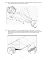
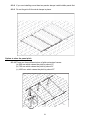
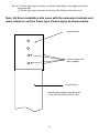
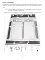
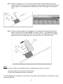
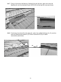
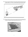
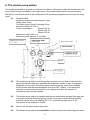
1
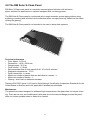
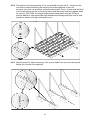
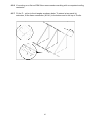
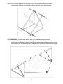
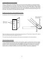
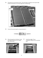
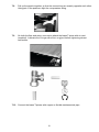
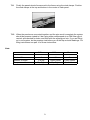
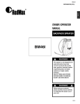
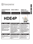
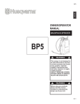
1 Instruction Manual Issue 2 2 0. Contents General Information Health and Safety Information..................................................................................................Page 4 Important Installer Tips.............................................................................................................Page 5 Working With Panels................................................................................................................Page 5 The RM Solar S Class Panel...................................................................................................Page 6 The RM Solar M Class Panel...................................................................................................Page 7 The RM Solar Econ Panel........................................................................................................Page 8 Positioning The Panels............................................................................................................Page 9 Frame Mounting On Roof Hook.........................................................................................................................Page 11 On Roof Slate.........................................................................................................................Page 17 On Roof Sharks Tail...............................................................................................................Page 23 Extending Frame For Econ....................................................................................................Page 29 In Roof Flashings...................................................................................................................Page 30 A Frame Installation...............................................................................................................Page 40 Exhibition A Frame & Gable Mounting...................................................................................Page 46 Piping And Setting Up Equipment Connecting S Class Panels....................................................................................................Page 48 Piping Up Econs Or M Class..................................................................................................Page 52 Double Pump Station.............................................................................................................Page 53 Expansion Vessel...................................................................................................................Page 55 Making Pipe Connections......................................................................................................Page 56 Insulation................................................................................................................................Page 57 Glycol.....................................................................................................................................Page 57 Filling The System..................................................................................................................Page 58 The Solar Controller...............................................................................................................Page 59 Solar Cylinders.......................................................................................................................Page 65 Commissioning And Guarantee Commissioning Certificate.....................................................................................................Page 66 Product Guarantee.................................................................................................................Page 67 Service Log Book...................................................................................................................Page 68 3 1. Health & Safety Information RM Solar panels are high quality thermal solar panels using selective coating technology to convert light into heat. RM Solar panels should only be fitted by authorised, trained and qualified personnel. They are not intended to be a “do it yourself” product. Panels are also sometimes called “solar collectors”. When fitting the panels installers should comply with all health and safety regulations and recommendations. Correct safety and protective clothing should be worn, including hard hats, boots, gloves and where appropriate eye protection. Subject to this we should point out some important matters. • When handling the collectors remember that they have been designed to convert light into heat and accordingly parts of them will get very hot if left out in the sun even for short periods of time. If you touch parts of the collectors after this exposure you may get severe burns because temperatures may well exceed boiling. • When working at heights always use correct scaffolding and safety harnesses. • Always assess the risks before you start work. • Take care when carrying the collectors to a roof. Carrying and manipulating heavy weights and large frames onto a roof is difficult and can cause you to slip. • Always make sure you have sufficient people to help you in your work. • Always comply with all wiring and electrical instructions and regulations, including bonding rules, when installing the pump station and controller. • Do not open or attempt to service the panels. There are no user serviceable parts inside. Unpack the panels carefully so that they are not damaged. The packaging is recyclable so please dispose of it in an environmentally friendly way. RM Solar systems are designed from high quality components intended for a long system life of working together as a thermal solar system. If you use any component that RM Solar has not approved all warranties will be void. 4 2. Important Installer Tips Always:• Use only solar quality O rings if you are using press fittings. • Do not install the panels upside down; they will only work the right way up. • Use support sleeves (pipes inserts). • Never use plastic pipes for the thermal circuit. • Join copper pipes by brazing, Compression fittings, or Press fittings, not with soft solder. • The glycol is ready mixed; do not add water or any other ingredient. • If you are not buying our pressure vessel, make sure the one you use has a glycol resistant membrane. • Pressure test the panels before you connect up the circuit, especially if you are fitting them inside the roof. 3. Working with panels (Storing, unpacking and moving the panels) Storing • Panels must be stored vertically against a wall or kept on the pallet until you are ready to install them. • Panels must not be stored on their horizontal sides because their pipes might be damaged. Unpacking • Unpack panels carefully so they are not damaged. The packaging is designed to be recyclable. Dispose of all packaging in an environmental friendly way by taking it to recycling centres. • Take care when carrying the panels to the roof. Carrying and manipulating heavy weights and large frames on the roof is difficult and can cause you to slip. Make sure that you have all necessary support harnesses and help for the job. Moving • Take care when the panels are exposed to the sun. The absorber plate and heat transfer reach ultra high temperatures in excess of 200 degrees Celsius and should not be touched whether the system is in operation or not, otherwise severe burns will be suffered. In very hot conditions shield the absorber parts of the panels from direct sunlight until the installation is complete. 5 4.0 The RM Solar S-Class Panel RM Solar S-Class solar panel is a vertically mounted glazed collector with collection pipes, intended for applications in systems equipped with circulating pumps. The RM Solar S-Class panel is constructed with a single meander system piping without using soldering or welding and is folded into the absorber plate; a single piece tray folded into the frame holding the glazing. The RM Solar S-Class panel is not intended to be used in drain-back systems. Technical Information • Floor Space : 2.03 m2 • Dimensions : 1010 x 2010 mm • Weight empty : 36.5 kg • Fluid Volume : 1.3 litres • Recommended flow of heat transfer fluid : 30 L/h/m2 collector • Stagnation temperature : 170°C • Panel connection : in series • Maximum number of panels that can be linked in a series : 3 • Maximum number of series : 1 • Glazing : 4mm low iron hailstone resistant Tested to EN 12975 (parts 1 & 2) and to Solar Rating & Certification Corporation Standards for the United States of America and to all applicable Canadian test standards Maintenance The panels have been designed to withstand high temperatures; the glass does not require cleaning. There are no user serviceable parts inside and due to the heat exchange process the panel does not contact potable water or water to be heated. 6 4.1 The RM Solar M-Class Panel The RM Solar M Class Panel has been specifically designed to meet the needs of large industrial applications. Suitable for both Commercial Buildings, and Private applications, such as large swimming pool installations. The M Class panels are also available as a horizontal variant allowing installation on roofs where space is a premium. The RM Solar M-Class panel is not intended to be used in drain-back systems. Technical Information • Floor Space : 2.03 m2 • Dimensions : 1010 x 2010 mm • Weight empty : 36.5 kg • Fluid Volume : 1.3 litres • Recommended flow of heat transfer fluid : 30 L/h/m2 collector • Stagnation temperature : 170°C • Panel connection : in parallel • Maximum number of panels that can be linked : 10 • Maximum number of series : Infinate • Glazing : 4mm low iron hailstone resistant Tested to EN 12975 (parts 1 & 2) and to Solar Rating & Certification Corporation Standards for the United States of America and to all applicable Canadian test standards Maintenance The panels have been designed to withstand high temperatures; the glass does not require cleaning. There are no user serviceable parts inside and due to the heat exchange process the panel does not contact potable water or water to be heated. 7 4.2 The RM Solar Econ Panel RM Solar’s new Econ range is supplied using the exact same equipment as the S Class and the M Class panels. When fitting the Econ panel please be aware that frame extenders are supplied in order to allow the panel to sit into the existing RM Solar Frame, instructions can be found on the fitting of these extenders in the on roof installation section. Technical Information • Floor Space : 2.01 m2 • Dimensions : 1005 x 2000 mm • Weight empty : 46 kg • Fluid Volume : 2.5 litres • Panel connection : in parallel • Maximum number of panels that can be linked : 5 • Maximum number of series : 1 • Glazing : 4mm low iron toughened glass Maintenance The panels have been designed to withstand high temperatures; the glass does not require cleaning. There are no user serviceable parts inside and due to the heat exchange process the panel does not contact potable water or water to be heated. 8 5. Positioning the panels 5.1 Generally south facing roofs Positioning the collectors is important for optimum performance. Collectors should ideally be mounted at an angle of between 30 degrees and 60 degrees on a south facing position that is not shaded by overhanging trees buildings or structures. Good results can be obtained by positioning the panels facing anywhere in an arc between south west and south east but due south facing provides optimum performance in the Northern Hemisphere. 5.2 North Facing Roofs It is not generally recommended that you install the panels on North facing roof in the Northern Hemisphere. South of the equator, north facing will provide optimum performance and south facing will provide the worse performance. 9 5.3 East/West facing roofs Good results can be obtained by splitting the collector array on East/West elevations but this should only be used when it is not possible to have a mainly southerly position for the collectors. If you are installing a split East/West system you have to double the number of the panels, e.g. 2 panels system requires 2 panels on East and 2 panels on West; each set of panels will behave as an independent system. A split system is not suitable for every East/West facing roofs. 5.4 East/West Alternative Another option is to oversize the collector area on the side of the roof chosen to mount the collectors. E.g. if 2 panels would have been adequate had the roof orientation been South, then 3 collectors would be used on either the East or the West depending on which side recieved the most sunshine. 10 6. Frame Mounting RM Solar offers three types of on – roof panel mounting and two types of in – roof panel mounting. On – roof installations • On – roof kit shark tail – suitable for most tiles. • On – roof kit hook – suitable for medium and large tiles. • On – roof kit slate – suitable for slate roofs. In – roof installations • Flashing kit for tile roof. • Flashing kit for slate roof. Flat Roof Installations or ground level installations • The “A” frame 6.1 On – roof Hook The on-roof hook installation is suitable for roofs which have a good wooden roof structure where the battens are sound. 11 6.1.1 When you unpack the on-roof frame packaging please check if any piece is missing. The package should contain: No. 1 2 3 5 1 2 4 5 On-Roof Hook Kit for a 2 Panel System Roof Hook L - Rail Z - Rail 2000mm Wind Clamp Bolt Kit (Bolt, Nut, Washer) M6 Long Wood Screw On-Roof Hook Extension Kit Roof Hook L - Rail Z - Rail 1000mm Wind Clamp Frame Connector Bolt Kit (Bolt, Nut, Washer) M6 12 Quantity 4 2 2 4 20 8 2 1 1 2 2 12 6.1.2 Check the roof battens for stability. The battens must not show any sign of deterioration. If the battens to be used are smaller than 30 x 50 mm you give them additional strength by adding additional battons (not supplied). 6.1.3 Place the roof hooks (1) as shown using 2 wood screws (4 x 30 mm). Fix the blade (2) under the lower roof batten. In case of roof tiles which are unusually thick you should carefully bend the blade of the hook, in order to fit under the batten and not just under the roof tile. The length of the roof hook should then be adjusted so that the hook part of it is the only part protruding after the roof tile is fitted over the hook. If necessary, file or grind part of the roof tile so that that the hook does not have contact with the tile. 13 6.1.4 WARNING: In areas of where heavy snowfalls are experienced you should replace each roof tile that covers a roof hook with a metal tile. If you do not do this the roof tile might break under heavy snow loads. 6.1.5 Use screw kit M8 x 20 to connect the L-rails to the roof hooks. BE CAREFUL that the frame rails are mounted with the five holes (8.5 mm) positioned at the highest part of the roof. 14 6.1.6 The Z-profile must next be fixed on to the L-rails, using the bolt kit M6. The maximum distance from a roof hook to the end of the Z-rail must not be more than 500 mm. If necessary, use an on- roof extension kit, following the same procedure. 6.1.7 Place the panels in position in the centre of the completed frame. In case of systems with more than two panels, mount the middle panel first. Mount the wind clamps to protect the panels using the nuts and bolts provided. 15 Option to raise the panel pitch 6.1.8 This option may be used to obtain a better incline for the panels than the roof allows. 6.1.9 Here are three different sizes of pitch extension frames: (a) 500 mm which raises the pitch by about 15° (b) 750 mm which raises the pitch by about 21° (c)1000 mm which raises the pitch by about 27° 6.1.11 (1) Remove the adjustable angle from the upper roof hooks. (2) Fit the extension rails on to the upper roof hooks using the nuts and bolts provided. (3) Mount the adjustable angles as shown. (4) Connect the L-rails on the lower side to the roof hook and on the upper side on to the extension rails. If necessary, drill appropriate holes into the rails. 16 6.2 On – roof slate mounting kit The slate roof mounting kit is suitable for of slate roofs, concrete roofs, pan tile and in windy areas. It is also suitable for roofs which have the roof tiles cemented permanently on to the roof structure. 6.2.1 When you unpack the slate roof frame packaging please check if any piece is missing. The package should contain: No. 1 2 3 6 7 On-Roof Slate 2 Panels Self Sealing Bolt Fitting L - Rail Z - Rail 2000mm Wind Clamps Right Angle Connector Bolt Kit (Bolt, Nut, Washer) M6 Quantity 4 2 2 4 4 30 No. 1 2 4 5 6 7 On-Roof Slate Extension Self Sealing Bolt Fitting L - Rail Z - Rail 1000mm Frame Connector Wind Clamp Right Angle Connector Screw Kit M6 17 Quantity 2 1 1 2 2 2 20 6.2.2 Locate the rafters under the slates. Mark the slates where the holes should be drilled so that the hole penetrates the centre of a rafter. Use the angle rail as a template. NOTE: The distance from the roof screw to the end of the Z-rail should not be more than 500 mm on each side. 18 6.2.3 Drill the holes on each marked position with a high quality 25 mm masonry bit. Make sure the drill does not spin too fast or you may break the tile/slate. Do not penetrate beyond the tile/slate. After drilling the holes into the tile/slates, use an 8 mm wood bit to make a hole through the rafters at each position. Bolt the bottom part of the self sealing bolt fitting into each drilled hole. 6.2.4 Use the bolt kit M6x 6 to connect the L-rails to the self sealing bolt fitting. TAKE CARE: The L-rails must be mounted into the long adjustable slot. 19 6.2.5 The Z-profile must be fitted to the L-rail using the bottom two holes that are below the long adjustable slot. Do not tighten fully. TAKE CARE: Make sure frame connector is fitted into the Z-profile properly if extending the frame to accomodate additonal panels. 6.2.6 Cross measure along the diagonals and check that they are equal. Once you are satisfied that each distance (A and B) on the drawing are equal, tighten fully. 20 6.2.7 After you place the panels into the frame and connect the panels together using the straight connectors and pipe inserts provided, fit the wind clamps to the frame using the nuts and bolts provided. Option to raise the pitch 6.2.8 There are three different sizes of pitch extension frames: (a) 500 mm which raises the pitch by about 15° (b) 750 mm which raises the pitch by about 21° (c) 1000 mm which raises the pitch by about 27° 6.2.9 (1) Fit the right angle connector on the top of the self sealing bolt fitting on the upper side screw extension rails (2) Fit the right angle connector to the top of the self sealing bolt fitting on the lower L-rail 21 (3) Fit the L-rail to the top of the extension rail and to the bottom of the right angle connection. 22 6.3 On – roof shark tail The on – roof shark tail mounting is suitable for thick and thin tiled roofs. 6.3.1 When you unpack the shark tail on-roof frame packaging please check if any piece is missing. The package should contain: No. 1 4 5 6 7, 8, 9 10 11 14 15, 16, 17 18 2 3 10 12 14 15, 16, 17 13 On-Roof Hook Kit for a 2 Panel System Support Pipe L = 2040mm Pipe Clamp Shark Tail U-Bolt M8 Bolt Kit (Bolt, Nut, Washer) M8 L - Rail L = 2010mm Z - Rail L = 2080mm Wind Clamps Bolt Kit (Bolt, Nut, Washer) M6 Long Wood Screw On-Roof Shark Tail Extension Kit Support Pipe L = 1040mm Pipe Connection L - Rail L = 2010mm Z - Rail L = 1040mm Wind Clamps Bolt Kit (Bolt, Nut, Washer) M6 Frame Connector 23 Quantity 2 6 4 4 8 2 2 4 20 14 2 2 1 2 2 8 2 24 6.3.2 Check the battens for stability. The battens must not show any signs of deterioration. Remove sufficient tiles to enable you to fit the shark tail. 6.3.3 Fit the lower fittings first. Screw the support pipe with help of the pipe clamps. The distance between support pipe and nearest batten below should be around 90mm. 25 6.3.4 Fit the U – bolt on the support pipe and on the top part of the shark tail. The shark tail should be placed no more than 500 mm from the end of the pipe. 6.3.5 Fit the L – rail on to the shark tail. Fit the top sharks tail to the L rail and lower on to roof, the top of the shark tail indicates where you should place the top support pipe. 26 6.3.6 Fit the support pipe to the top shark tails. The shark tail must be upright. Then fit the shark tails and support pipe together with U-Bolts. 6.3.7 After you placed the L – rails into position, fit the Z – rails on the L – rail. Do not tighten bolts fully. Cross measure along the diagonals and check that they are equal. Once you are satisfied that each diagonal (A and B on the drawing) are equal, tighten fully. 27 6.3.8 If you are installing more than two panels always install middle panel first. 6.3.9 Do not forget to fit the wind clamps in place. Option to raise the panel pitch 6.3.10 There are three different sizes of pitch extension frames: (a) 500 mm which raises the pitch by about 15° (b) 750 mm which raises the pitch by about 21° (c) 1000 mm which raises the pitch by about 27° 28 6.3.11 (1) Fit the right angle connector on the top of the fitting on the upper side screw extension rails (2) Fit the right angle connector to the top of the fitting on the lower L-rail Note: All Econ installation kits come with the extension brackets and wind clamps to suit the frame type. Please apply as shown below. Frame Extender Secure in place with bolts supplied Original Frame Note: Must be installed at the top of the L - Rail. NOT the bottom of the L - Rail. 29 6.4 In – roof fittings The standard in roof mounting kit is designed to accommodate ‘S’ & ‘M’ class panel systems and is suitable for most types of roofs. There are two different kits, one for tiled roofs and one for slate roofs. 6.4.1 When you unpack the in-roof frame kit from its packaging, please check if any part is missing. The package should contain: 30 No. 1 2 3 4 5 6 7 8 9 10 11 12 13 14 15 16 17 18 19 20 21 22 In - Roof 2 Panel Tile Kit Angle Iron Lower Wooden Slat Lower Left Flashing Lower Center Flashing Lower Right Flashing Lower Seal Strips Upper Wedge Side Slat Side Seal Strip Left Side Flashing Right Side Flashing Center Flashing Upper Seal Strip Wind Retaining Rail Upper Left Flashing Upper Center Flashing Upper Right Flashing Triangular Seal Wood Screws (5x110) Wood Screws (4x30) Screws with washer and seal small Nail Strips 31 Quantity 6 2 1 1 1 3 2 1 8m 1 1 1 2 2 1 1 1 2 15 57 26 15 6.4.2 Determine where the panels will be mounted and check the roof tile alignment. 6.4.3 Remove the tiles/slate from the roof according to the size of system you are fitting. For a two panel installation a tiled/slate area of 2600 x 2600 should be removed. For every additional panel remove a further tiled area of 1100 x 2600. 6.4.4 Attach a lower support batten. Screw the lower support batten to the rafter along where the panels are going to be placed. Use wood screws (4.5 x 80). NOTE: These battens and screws are not supplied! Use good quality batten wood, preferably from sustainable sources. 32 6.4.5 Attach the angle irons (1) to the lower support batten at equal distances using 3 screws, 4x30 (20). If more than two panels are to be installed, fit the first and the last angle, tighten a cord between them and place the rest of the angle irons along the cord. 6.4.6 Attach the lower wooden slat (2) with the cut off edge placed toward the panel as shown. Use 4x30 (20) screws. NOTE: The slats in the in – roof installation set are longer than the ones in the extension set. The slats of the installation set should be placed on the left and right side of the extension slat (For 3 Panel Kit Only). Note: Before the side, middle and top flashing part is installed make sure that you have: - Pressure tested the connections of the panels. - Placed the temperature sensor in the panel. Once the flashing kit is finished you will either not be able to do these tasks, or be able to do them with great difficulty. 33 6.4.7 Fitting of the lower left flashing: Starting from the left side, place the lower left flashing (3) onto the slat and screw it 4x30 (20) at the top left corner as shown. 6.4.8 Continuing from the left to the right side, place the middle flashings (4), (5) onto the slat and interlock with section (3). Place a screw 4x30 (20) on each connection (see below). 34 6.4.9 Place the upper support wedge so that the distance between the lower slat (2) and the upper wedge (7) is 1950 mm. The upper wedge must be supported by at least two battens (Only use one 110mm screw to hold the wedge in place at this point) 6.4.10 Seal strip: Stick the seal strip (6) along the whole edge of the lower flashing (3) (4) (5). Place the panels and align them. The distance on each side of the field should be 100mm. It is important to check diagonal measurements. A = B. 35 6.4.11 Panels should be 100mm from the edge of bottom flashing. 6.4.12 Mounting the upper wedge: now secure the upper wedge (7) in place using 6 x 110mm screws (In Total). 6.4.13 Connect the panels together and connect them with pipes (see chapter 5.) and pressure test the system using either compressed air, or the glycol solution NOT water. 6.4.14 Insert the panel temperature sensor (brown wire). 36 6.4.15. Mount the middle and side wooden rafters. Using 3 x 110mm screws in each 6.4.16. Paste the adhesive backed black strip to the side panel edge and fix the middle flashing kit on the middle wooden rafter using the coloured screws 6.4.17. Next fix the left and right hand edge flashing using the capped coloured screws as shown 37 6.4.18. Fixing the side flashing 6.4.19. Using the nails and clips shown below (1), secure the side flashings to the tile battons by hooking the clips over the outside edge of the flashings and nailing into the batton as shown below (2) 6.4.20. Fix another timber rail (not supplied) across 6.4.21. Paste the adhesive backed the top of the array, 280mm above the bib black strip along the top of flashing support rail fixed earlier. panels and flashing. See figure below. 6.4.22. Screw the wind retaining rail on the timber rail 38 6.4.23. Fix the top flashing kit – left part 6.4.24. The middle part of the flashing kit interlocks with the left part 6.4.25. Fix the right part of the top flashing kit. 6.4.26. When you have firmly fixed all flashing the roof tiles/slates can be replaced. 39 6.5 Flat roof and free standing The A – frame is suitable for any kind of flat roof and it is also is suitable for ground installation. 6.5.1 When you unpack the A-frame kit packaging please check if any piece is missing. The package should contain: No. 1 2 3 4 5 6 No. 2 3 4 6 7 8 A - Frame kit for 2 panels Z-rail 2040 mm L-rail Basic rail Support rail Cross rail Wind clamps Bolt kit (Bolt, Nut, Washer) M6x16 A - Frame Extension L-rail Basic rail Support rail Wind clamp Z-rail 1040 mm Frame connector Bolt kit (Bolt, Nut, Washer) M6x16 40 Quantity 2 2 2 2 1 4 30 Quantity 1 1 1 2 2 1 12 6.5.2 Fit together the basic rail, support rail and L-rail using the nuts and bolts provided. You will create triangular structures as shown in the diagram. 6.5.3 The distance between each triangle should be approximately 1200 - 1300mm 41 6.5.4 First option for frame mounting: If it is not possible to screw the A – frame into the roof directly without affecting the integrity and water tightness of the roof structure you must use a special concrete-metal sheet. The A – frame must be fixed to the sheet placed on the roof and the frame and the sheet must be weighed down for security. CAUTION: the weight holding down each panel must be 350 kg to provide stability in high winds although installers should pay particular care in local conditions where very high wind speed occur. 6.5.5 Second option for frame mounting: If the roof is made from concrete use special fittings for concrete (not supplied). 42 6.5.6 If mounting on a flat roof RM Solar recommends consulting with a competent roofing contractor. 6.5.7 Fit the Z – rail on to the triangles as shown below. To extend a two panel kit extension, fit the frame connection (K1141) to the bottom and to the top of Z-rails. 43 6.5.8 When the Z – rail has been fitted to the triangle, bolt the cross rail on the back of the frame construction. NOTE: Drill Ø 8 mm holes into the support rail as necessary. 6.5.9 WARNING: If the installation is more than 2 collectors, install the middle collector first. 6.5.10 When you have finished building the frame and fitting the panels, do not forget to fit the wind clamps. 44 6.5.11 If the overall length of the A frame is to be more than 8 metres the frame construction must be secured with another support rail as shown below. 6.5.12 WARNING: In areas with strong wind you must take into account the possibility of wind resistance which may cause the whole frame and panel construction to vibrate. In these cases fit one more support triangles at the end of each side of the A frame as shown. This will make the whole construction stronger. 45 6.6 Gable/Wall Mounting/Exhibition A Frames This A frame has a steeper incline than the normal A Frame, making it suitable for mounting onto gable ends, wall mounting, and for on roof installation with a shallower incline. Z-Rail Cross bracing should be applied to the bottom of the A-Frame, this is however not supplied in the kit and should be sought seperately. 46 Joining Exhibition A Frames Together When you have constructed both frames you will connect them together by inserting the frame connector (FIX0302) into the Z-Rail. The frame connector will be inserted approximately 180mm into the Z-Rail at the top and bottom of the frame. There are no pre-drilled holes in these Z-Rails to insert the bolts so you will require a 6.5mm H.S.S. bit to affix them. (Two bolts for each Z-Rail). Take the next frame and slide the Z-Rails onto the frame connectors that are protruding from the first frame, drill and bolt. The frames will now be joined. Exhibition A Frame alts. to Accomodate Econ Panels At the base of the A-Frame uprights are two holes (A) These will be the new holes (B) Bolt Into (A) on A Frame (A) Take the extensions and bolt it onto the frame using holes (A). Then with a 6.5mm H.S.S. drill bit drill the two holes beneath the original holes (A). The new holes drilled (B) will now hold the bottom horizontal bar in the correct position. Gable Mounting Instructions The A-Frames can be mounted to either a strong wall or gable end. Once the frames have been constructed drill adequate holes in the back support rails and raw bolt the frame on to the gable end/wall. If there is any doubt whether the wall/gable can support the weight of the solar array please consult a structural engineer. We cannot be responsible for errors made in not taking expert advice, as different walls and structures have different load bearing capabilities. 47 7. Panel connections and Pressure Testing 7.1 There are two separate kits; the installation kit is used for connecting the panels to the heat exchange loop and the extension kit is used for connecting one panel to another. 7.2 Before you place the panels on the frame and connect them check the diagonals to make sure the top and bottom rails are square. 7.3 Place the panels in position in the centre of the completed frame. In case of the systems with more than two panels, mount the middle panel first 48 7.4 The panels are connected in series. The inlet (return) is always on the top left side and the outlet (flow) is on the top right side. (S Class Only) Connect the panels together using extension kit 7.5 7.6 Place the panels on the frame. Insert 7.7 the support sleeves into the copper pipe connections. 49 Insert the straight 12 mm compression fitting on the connection pipe. 7.8 Pull up the panels together, so that the connections are exactly opposite each other. Using pair of the spanners tight the compression fitting. 7.9 On both the flow and return connection attach the brass T-piece with air vent (supplied). Lubricate the O-rings with silicon or glycol before tightening airvent connection. 7.10 Connect the brass T-pieces with copper or flexible stainless steel pipe. 50 7.11 Finally the panels should be secured to the frame using the wind clamps. Position the wind clamps at the top and bottom in the centre of each panel. 7.12 When the panels are connected together and the pipe work is complete the system should be pressure tested to 6 bar using either compressed air or RM Solar glycol, vented, and checked for leaks, and filled with the water/glycol mix. If you are fitting an in roof system, do the pressure test before you fit the top and side flashings. For filling instructions see part 14 of these instructions. Note: Max In A Row Number Of Inlets Temperature Sensor S Class M Class Econ 3 2 at top Top Right 10 1 each corner Top Right 5 1 each corner On Air Vent 51 Piping up the Econ and M Class Panels Return Airvent 1st Row A Panel Panel Panel A Panel Panel Panel 2nd Row if applicable A A Flow A = Stop End 52 8. The double pump station The double pump station ensures a continuous circulation of the glycol inside the closed solar loop when useful energy is available in the solar panels. The double pump station recommended by RM Solar is constructed so as to be unaffected by the operating temperatures of the loop for many years. 8.1 Technical data: Maximum working excess pressure: 6 bar Safety valve: 6 bar Circulation pump: Solar Circulating Pump Nominal voltage: AC 230 V Power consumption: Speed 1 45 W Speed 2 65 W Speed 3 90 W Maximum pump head: 6 m Maximum pump capacity: 4,5 Ltr/Min 8.2 The double pump station must always be mounted at a level that is lower than the panels so that no steam may penetrate the expansion vessel in case of stagnation. Stagnation occurs when the solar panels have heat energy which is not needed by the system and the panels stagnate at around 180° Celsius. If the expansion vessel is mounted at the same level or at a higher lever than the panels, an anti-gravity loop must be installed. 8.3 The double pump station is supplied with the two temperature gauges (flow pipe and return pipe) with pre-fitted flow gauge. On the return pipe is a pre-fitted the safety pressure relieve valve with tapping (RP 3/4’’), a pressure guage and a G 3/4” connection for the expansion vessel. 8.4 Never flush the solar system with water. 8.5 The double pump station is not suitable for direct contact with swimming pool water. 53 8.6 Flow settings: The flow regulator should be set to 0.5 to 1.0 litre per minute per panel. A three-panel installation is set to a flow rate of 1.5 to 3 litres per minute. How to read the flow setter: 8.7 Pressure settings: The maximum pressure is 6 bar. Once the system is pressurised keep the pressure between 3 – 4 bar. With higher pressure inside the system, the glycol/mix will not evaporate until temperatures of around 120°Celsius are reached. Pressurisation therefore helps to prevent glycol degradation and enables more useful heat energy to be applied. 8.8 Maintenance: The double pump station does not require maintenance. It is fully controlled by the digital controller. The customer should do a visual check every month for leaks, significant different readings on the temperature gauges and readings on digital controller, pressure drop below red line on the pressure gauge can indicate a leak on the system. The customer should be informed that fluctuations in pressure readings while the system is operating are perfectly normal. In case of any unexpected changes, the customer must contact the installer immediately. Note: A competent solar engineer should service the system 3 years after install, and then every 2 years there after. 54 9. Expansion vessel (also known as expansion tank or pressure vessel) 9.1 Function of the Expansion Vessel An expansion vessel protects the solar system during pressure changes and temperatures fluctuations. For example, in very hot conditions when energy is not being drawn off, the system may overheat causing the glycol to expand. 9.2 Technical information: Maximum pressure: 10 bar Working pressure: 3.0 – 4.0 bar (20°C) Gas pressure: 2.5 bar Maximum working temperature: 130°C Membrane: Nytril (butyl) rubber Resistance: 40 % glycol 9.3 Expansion vessel sizing: It is of critical importance to have the correct size of expansion vessel in your solar system. The volume of the expansion vessel is determined by the number of RM Solar solar panels connected within the one solar heating system. For one collector 6 Litres of the expansion vessel volume is required. Please use the right size expansion vessel, and we set out a table below to help you chose the correct size: Number Of Collectors 2 3 3+ Expansion Vessel Size 18 18 Please call for details 9.4 Location: The pressure vessel should be located in a position where it can be easily accessed. It should be fitted with isolating valve for ease of replacement. The isolating valve should not be accessible without a tool so that an unqualified person cannot shut it off. The expansion vessel should be fitted on the return run of the system. 9.5 Maintenance: Once an expansion vessel is pressurised correctly it does not require maintenance although we strongly recommend a visual inspection by a qualified person at least once a year. Monthly checking of the pressure gauge on the double pump station is also very important. A pressure drop might indicate: • A leak on the pipes connections or • A leak on the panels connections or • A faulty expansion vessel In the case of any unexpected changes, the customer must contact the installer immediately and the installer should inform the customer of this when explaining the system. 55 10. Piping and pipes connections 10.1 Piping The copper heat exchange pipe in RM Solar panels contain glycol, pressurised and heated to temperatures in excess of 170ºC when exposed to direct sunlight where the rays are striking the absorber plate at roughly a right angle. This heating process takes place very quickly. Similar temperatures will be reached in winter, but more slowly due to the lower levels of insolation. In winter at night the system is designed to be safe to temperatures of minus 30º C or lower. It will perform in winter in the right insolation conditions and in below freezing temperatures. Copper piping is used because copper is highly efficient in heat exchange operations because the thermal conductivity is high. The copper piping will be exposed to high and low heat, including high variable heat. Three points should be made:• Copper does not become brittle at low temperatures. • The melting point of copper is 1083°C. • The grade of copper used by RM Solar will not become hard (like steel) if it is cooled rapidly after heating. Internally, the collector heat pipe, is folded into the absorber tray and is one continuous tube which is hard soldered in two places only as part of the connective pipe. We accordingly recommend that best quality copper pipe is used in the heat ex change loop, or stainless steel flexible pipe is used. NOTE: On RM Solar system you must not use plastic pipe in the heat exchange circuit due to very high temperatures the system generates. Using plastic pipes might cause major injuries in the almost certain event that the plastic will explode under the combination of temperatures and pressures generated. 10.2 Pipes connections RM Solar systems are either “hard” soldered or preferably connected by press fittings, which allow fast, safe and efficient joints to be made. We recommend the use of press tools powered by a rechargeable battery to achieve a sound joint without the need for solder, flux or any other jointing materials. This creates extremely sound pressure proof joints without soldering or brazing. This is particularly important as the glycol solution has a much lower surface tension than water and will find cracks and crevices in pipe work and jointing that water will not find. The fact that the heat transfer system is pressurised also requires the integrity of the pipe work to be paramount. 10.3 The RM Solar recommends using thick-walled copper or gunmetal fittings that have a machined bead – similar to a solder ring fitting – containing an O-ring. This is pressed onto copper tube using the tool fitted with the appropriate clamp. Or alternatively use good quality compression fittings. O rings If you use press fitting please remember to use solar quality O rings, rather than traditional plumbing O rings. Solar quality O rings will not melt at the temperatures experienced inside the thermal loop. 56 11. Insulation The use of the correct insulation is critical. Normal central heating insulation will melt and become brittle at the very high solar generated temperatures in the system. Insulation materials must endure the highest occurring temperature, which will be more than 170oC near the collector. Where the insulation is outdoors then it must be: • Resistant to temperatures up to 170°C • Must have a flexibility in - 30°C conditions • Resistant to air pollution • Resistance to UV radiation • Resistance to pests, such as mice and birds that may eat it. In some countries the activities of insects require insulation to be “armoured” or sheathed • Insulation should be externally sealed to prevent it carrying moisture. 12. Glycol The glycol is heat exchanging fluid with a very low freezing point, already pre-mixed to 40%. Glycol supplied by RM Solar has following properties: • Glycol 40 % pre - mixed has anti-freeze protection up to -40°C • Contains anti-corrosion inhibitors for pipe protection • Glycol is a low toxic polypropylene product approved for use in solar systems by all major countries including the USA and EU • The glycol contains a harmless pink dye so that if there is a failure of the water cylinder or storage tank, the dye will warn the consumer of that fact and allow the consumer to call the installer • Glycol has a notably more intensive creeping property than water • Glycol is not compatible with zinc. So pipes with internal zinc galvanising should not be used • Chemical nature: Propane 1.2 with corrosion inhibitors • As with all chemicals, normal precautions should be taken in handling the glycol to prevent • ingestion and delivery into the water system Note: Under no circumstances should any ethylene based glycol be used in solar systems. The material safety data sheet for the RM Solar glycol is available from RM Solar on request. 57 13. Filling the system with glycol When the solar heating system is filled with heat exchange liquid (Glycol), the heat transfer medium displaces any air. The correct system charging will ensure that the solar system will run without pressure losses and with high performance. However carefully you fill the system manually, small bubbles of air might be caught in ‘air locks’ inside the pipes and some of these air locks will be from air naturally dissolved in the water part of the glycol solution. Using the automatic filling pump station design by RM Solar you will reduce the occurrence of air locks and save time bleeding the system. (This is compatible with most solar systems). Legend: 1. Tray for Glycol 2. Suction Hole 3. Filter 4. Blow Hole 5. PVC Pipe for flow 6. PVC Pipe for return 7. Damper 8. Pump 9. Drain Hole 10. High Voltage Cable 11. Switcher ON/OFF Connecting the filling pump to the Double pump station: 13.1 Place the filling pump station on secure, horizontally clear place, close to the double pump station so the hoses of 2 m can connect to the double pump station 13.2 Connect the hoses from filling pump station to the double pump station 13.3 The flow hose (5) connect on the part of the double pump station where the safety relieve valve (A) is located 13.4 The return hose (6) connect to the valve below the solar pump next to flow setter (B) 13.5 Fill the tray with glycol 13.6 Make sure the filling station switch is off and plug the pump into a convenient socket 13.7 Switch the filling pump station on and open the valves A and B - closing the grub screw above the flow setter 13.8 Be prepared to carefully add additional glycol as needed to the tray while it is operating 13.9 Leave to circulate for an hour 58 14. The digital controller DC12 The digital controller DC12 is able to control one hydraulic circuit on the solar system for example a hot domestic water system, or a swimming pool heating system or a heating system. It cannot control more than a single circuit, so that it cannot control an installation which heats water and a swimming pool at the same time. The controller has been designed for universal multi-language usage. The display contains a simple schematic of the hydraulic scheme which you have set up, with the information of the operating mode and pre-set information of the temperatures or a pump speed. The DC12 controller has some functions protected by password. A customer should not be provided with the password because the customer may well program wrong settings which might cause the solar heating system to misfunction. The values and settings on the DC12 are divided into the three groups: • Operating modes • Information • Settings 59 1. Operating Modes - The controller can be switched into the three different operating modes (ON,OFF, Manual) - Each operating mode is displayed on the display in the left top corner. • Automatic • Off • Manual How to change the values? When the controller is showing AUTOMATIC press the ENTER button. The sign will start flash and by pressing right/left arrow you can change the operating mode. When you have chosen right operating mode press the ENTER button key (marked with a tick). 2. Information display - Once the operating mode has been set, you can move down on the display with right arrow, which brings you to an option – Information - It will be shown on the display as: • Information i - For entering the Information part press Enter button - Move forward or backward by pressing left or right arrowheads. - This function allows you to see the actual, set values and the calculated values can be displayed with pressing right or left arrowheads. 60 What the signs mean: This is the actual temperature at the panels A minimum temp requirement at the panels for system to next switch on This is only a reading - it cannot be adjusted It is minimum set temperature. If the temperature drops below set temperature the system will turn off This is the temp at the cylinder This is just a reading An actual temperature reading at the cylinder This is the minimum required temperature at the cylinder Pump speed This is just a reading Please note: the menu item “additional settings” do not apply for DC12 and have no function for the DC12 3. Settings - This mode will be shown on the main display when you press the right button until you see sign: • Settings SET - Each setting has been marked by key numbers. A list of the key numbers is explained in the instruction manual for DC 12 - I would like to highlight those which must be re-set so that the controller will work efficiently. - The settings are divided into the two groups. One is without the password and second group can be adjusted only with password. Settings without the password Key number: 8-62 - Minimum temperature required at the cylinder (pre-set by manufacturer) 60°C. - Do not set this value above 70oC How do you change the value? While you are on the mode SET, press the TICK button. The key number (8-62) will appear below hydraulic scheme. Press enter again and the pre-set value starts flash. With right or left button you will be able to change the value. Press the TICK button again. When you press the right button you will go to following key number which is 8-63 and after another press to 8-85. 61 Key number: 8-85 - This value allows us to set speed of the double pump station in manual operation. - Manufacturer setting is 0 % and must be changed to 100% (see paragraph ‘How to change the values’). Settings with the password - Once you set the values under key numbers: 8-62 and 8-85, press right button which brings you to values where you have to insert the password number 25 - That will bring you to a second group of values which must be adjusted as follows: Please note: I will describe only those which must be changed and full description of the key numbers you can find in the instruction manual Key number: 8-01 - A minimum difference between temperatures on the panels and the cylinder to switch the double pump station ON - A manufacturer pre-set value : 15 K (can be changed) Key number: 8-02 - A minimum difference between temperatures on the panels and the cylinder to switch the double pump station OFF - A manufacturer pre-set value : 5 K (can be changed) Key number: 8-30 - A solar nominal panel performance. - A solar nominal panel performance is based for the calculation of the actual panel performance together with the flow setting (8-37). Dependent of the actual panel performance the digital controller can modulate pump speed and controller flow which will increase performance and efficiency of the solar system. - A manufacturer pre-set value is 8 kW. You must change this value to 6 kW for every RM Solar system. Key number: 8-35 - Minimum pump speed in auto mode. - A manufacturer pre-set value is 50%. You must change this value to 100% for every RM Solar system. Key number: 8-37 - This value allows us to set the flow on the solar system (no electronic flow meter is needed). - The flow is 1 L/min per collector. For two panel system the value is 2 L/min. - If you install more than three panels this value must be changed. 3 panels – 3 L/min 4 panels – 4 L/min 5 panels – 5 L/min And so on 62 Remember: After you made any change on the values you must press the ENTER button so controller can take the new settings. When you finished with above settings press the X button until you return to the main display. Your digital controller is now set properly and will control solar heating system correctly and more efficiently. PLEASE NOTE: Read the instruction manual properly. It contains lots of important information, at the back there is a fault finding section. Do not make any changes on the controller which we have not set out in this letter. Of course, in case of any queries please contact me for help. A check list of the changes that you must make every time: Key Number 8-62 8-85 8-01 8-02 8-30 8-35 8-37 Pre-set values 60 (oC) 0 (%) 15 (K) 8 (K) 8 (kW) 50 (%) 2 (L/Min) New values 60 - 70 (oC) 100 (%) 8 - 15 (K) 3 - 5 (K) 6 (kW) 100 (%) For more than 2 panel systems the value must be changed as shown above Note: When commissoning is complete leave the controller in automatic mode. 63 E 1 2 N N DC12 Solar Controller N N 3 ECO C ECO for Solar 3 4 4 5 5 6 6 7 7 8 8 9 10 9 10 Wiring centre Boiler Primary ECO in Duostat ECO For Solar LowerTank sensor E 2 3 2 1 2 C 1 1 Control 2 E N E C L N E Solar Pump L E Boiler primary duostat 2 Schematic wiring with Solar Controller (1 Hydraulic Circuit) L Lower Tank sensor B1 T B2 T Panel sensor N E Solar circuit Motorised valve If fitted L 64 65 Commissioning Certificate COLLECTORS Collector type ...………………………… Number of panels ………………………..….. MOUNTING (please tick) Separate modules on roof ……………….…..….. “A” Frame ……………..…….….…. Roof integrated ……………………….................. Above roof ………………..…......... STORAGE Number of cylinders …………………..... Nominal volume Dimensions: Height ….………...…..mm Diameter ……………………....litres ...………………….…..mm PRIMARY CIRCUIT Pipe size ………………………….......mm Pump c/w valves Type ……………….. Model Pressure relief valve ……..…………mm Blow off pressure Flow rate ……………….……….litres/min Drain valve Lockshield valves Number………………. Size Antifreeze/inhibitor Make……………..….. Quantity ………………………....… …..…………….……...bar …………………….....mm …………………….....mm ……………....……...litres FOR FULLY FILLED SYSTEMS ONLY Expansion vessel Size…….……….litres Pressure gauge range ……………..…....bar SECONDRY CIRCUIT (WHERE APPROPRIATE) Three way diverter valve Type…………................ Thermal mixing valve Type…………………..… Pressure reducing valve Type…………………..… Size ..……………………..…… Size ..………………………..… Size ………………………….… CONTROL EQUIPEMENT Fused spur ……………………………..…..…..Amp Differential temperature controller Make …………………………………………………......... (c/w sensors) Model ……………………………..…………………........... Electric cable ………....…….mm2 Sensor extension cable ...………........mm2 PIPE INSULATION Internal Type………………………....................... External Type…………………………..…………... INSTALLATION BY Company .…………………………………. Installer ………………..……………..…. Thickness .....…………...………...mm Thickness ……………….......……mm Date ……………………………. Contact Number ……………………………. 66 RM SOLAR PRODUCT GUARANTEE RM Solar Products are guaranteed by RM Solar Ltd as follows: Thermal Solar Panels (Performance) (S-Class & M-Class ONLY) Thermal Solar Panels (Against corrosion) (S-Class & M-Class ONLY) Thermal Solar Panels (Manufacturers guarantee) (ECON) Pump Stations, Controllers & Heat Exchangers Other RM Solar products 20 years 20 years 8 years 2 years 1 year In all cases, from the day system was commissioned. The Guarantee is conditional upon: 1. 2. 3. 4. The solar system is installed by an approved RM Solar installer in accordance with recommended RM Solar techniques and practises, and is serviced inline with our recommendations, and a full service history is recorded. The installation is paid for in full. Customer completing the enclosed Registration Form, (which also needs to be countersigned by the installer) and sending it to RM Solar Ltd within 28 days of it commissioning. RM Solar Ltd being notified of any circumstances giving rise to a claim hereunder within 28 days of such circumstance arising. This Guarantee DOES NOT cover: 1. 2. Hot water cylinders and thermal stores, which are separately guaranteed by their own manufacturers. Workmanship, which is separately guaranteed by the installer. All statutory rights are not affected by this guarantee and every subsequent owner of the property at which the thermal solar installation is installed will be recognised hereunder RM Solar Ltd. All enquiries and claims hereunder should be addressed to: RM Solar Ltd, 4 Valencia Park, Gilcar Way, Wakefield Europort, Castleford, West Yorkshire, WF10 5QS Or to: [email protected] -------------------------------------------------------------------------------------------------------------------------------------REGISTRATION FORM Customer Address of installation Post code E-mail If in the future you would like to receive information regarding new RM Solar environmental, energy products, services and developments please tick here System Type (please tick) S-CLASS ECON M-CLASS Serial Number Company Name of Installer Installer counter signature Print: Sign: Date system was commissioned 67 Service Record SERVICE 1 SERVICE 2 DATE: ENGINEER NAME: ENGINEER NAME: COMPANY NAME: COMPANY NAME: TEL NO. TEL NO. COMMENTS: COMMENTS: SIGNATURE: SIGNATURE: SERVICE 3 SERVICE 4 DATE: ENGINEER NAME: ENGINEER NAME: COMPANY NAME: COMPANY NAME: TEL NO. TEL NO. COMMENTS: COMMENTS: SIGNATURE: SIGNATURE: SERVICE 5 SERVICE 6 DATE: ENGINEER NAME: ENGINEER NAME: COMPANY NAME: COMPANY NAME: TEL NO. TEL NO. COMMENTS: COMMENTS: SIGNATURE: SIGNATURE: SERVICE 7 SERVICE 8 DATE: ENGINEER NAME: ENGINEER NAME: COMPANY NAME: COMPANY NAME: TEL NO. TEL NO. COMMENTS: COMMENTS: SIGNATURE: SIGNATURE: SERVICE 9 SERVICE 10 DATE: ENGINEER NAME: ENGINEER NAME: COMPANY NAME: COMPANY NAME: TEL NO. TEL NO. COMMENTS: COMMENTS: SIGNATURE: SIGNATURE: SERVICE 11 SERVICE 12 DATE: ENGINEER NAME: ENGINEER NAME: COMPANY NAME: COMPANY NAME: TEL NO. TEL NO. COMMENTS: COMMENTS: SIGNATURE: SIGNATURE: 68 DATE: DATE: DATE: DATE: DATE: DATE: