1
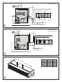
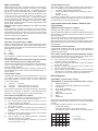
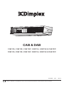
CAB & DAB
CAB10A, CAB10E, CAB10W, CAB15A, CAB15E & CAB15W
DAB10A, DAB10E, DAB10W, DAB15A, DAB15E & DAB15W
08/19023/6
(UK)
Issue 6
The product complies with the European Safety Standards EN60335-2-30 and the European Standard Electromagnetic Compatibility (EMC)
EN55014, EN60555-2 and EN60555-3 which cover the essential requirements of EEC Directives 73/23 and 89/336
1
W
L
a
H
b
L
1065
1569
1057
1557
CAB 10 E/W/A
CAB 15 E/W/A
DAB 10 E/W/A
DAB 15 E/W/A
W
320
320
391
391
H
262
262
361
361
A
1
100mm MIN.
'x'
A
920
1425
920
1425
CAB 10
CAB 15
DAB 10
DAB 15
B
160
160
230
230
B
2
2.0m Min.
2
3b
3a
b
a
'z'
c
'w'
'y'
'x'
4
5
a
b
6A
b
a
CAB E
6B
a
DAB E
6C
d
b
b
CAB W / A
6D
a
DAB W / A
CAB ‘E’ & DAB ‘E’
380-415 V 3PN
M
N L1 L2 L3
D
F
N
C
GND
M1
M2
H1
H2
A
E
bms
M1
B
7
bms
H1
bms
M2
bms
H2
G
CAB ‘A’ & DAB ‘A’
CAB ‘W’ & DAB ‘W’
220-240V 1PN
M
D
N L
N
GND
M1
M2
A
bms
M1
B
bms
M2
G
8
Y
X
9
CAB
CAB
DAB
DAB
10
15
10
15
X
840
1260
800
1300
Y
240
240
300
300
Dimplex Compact Air Curtains
Models :
CAB10E, CAB15E, CAB10W, CAB15W, CAB10A, & CAB15A
DAB10E, DAB15E, DAB10W, DAB15W, DAB10A, & DAB15A
IMPORTANT: THESE INSTRUCTIONS SHOULD BE READ CAREFULLY AND RETAINED FOR FUTURE REFERENCE
IMPORTANT SAFETY ADVICE
The distance between the bottom of the appliance and the top of
a door should be kept to a minimum - see ‘b’ in Fig. 1.
DO NOT COVER OR OBSTRUCT the air inlet or outlet grille.
Wall Mounting
ENSURE THE APPLIANCE IS EARTHED.
Using the wall mounting bracket as a guide (see Fig. 2) mark off
hole positions on the wall (a minimum height of 2.0 metres is
required from the floor level to the bottom of the bracket). Position
the bracket such that the air outlet of the installed air curtain will
be as close to the top of the doorway as possible but will remain
unobstructed when installation is complete.
Solid brick or concrete block walls must be drilled and plugged
(using a spirit level as a guide - see ‘x’ in Fig. 2 - to ensure the
bracket is level) with rawlplug No. 8 size fibre inserts. The plug
must be located in the solid part of the wall and not just in the
plaster layer.
When fixing to ‘panel’ walls, the wall bracket should be attached
to the stud-work using No. 8 wood screws or by an alternative,
equally secure method of fixing.
Once the wall bracket has been fitted, the air curtain can be
clipped in place as shown in Fig. 3a.
Do not use this heater in areas where excessive dust exists.
This heater must not be located immediately above or below
a fixed socket outlet or connection box.
Always disconnect supply before working on the product.
This appliance should only be connected to the fixed wiring
of the premises by means of conduit.
This product should be mounted safely to solid wall or ceiling
surfaces only.
This product must not be subjected to water spray or
immersion.
Ensure the supply cables are of adequate current carrying
capacity and are protected by a suitable fuse.
If the appliance is mounted in a toilet or washroom, the
appliance should be mounted such that no part of it can be
touched by a person using a fixed bath or shower.
If the appliance is mounted in a toilet or washroom an
isolating switch must be provided outside the washroom
adjacent to the entrance door.
WARNING: Isolate electrical supply to ALL modular linked
units when carrying out maintenance.
Models
Model
Heat
output
Electrical
Supply
Electrical
load
Weight
Max
Installed
height
A
kg
m
(per phase)
kW
AMBIENT / COLD STORE
CAB10A
n/a
220-240V ~1PN
0.3
15.5
3.0
CAB15A
n/a
220-240V ~1PN
0.5
21.5
3.0
DAB10A
DAB15A
n/a
220-240V ~1PN
220-240V ~1PN
1.5
2.3
21.5
27.5
4.0
4.0
n/a
ELECTRICALLY HEATED
CAB10E
4.5 / 9.0
380-415V ~3PN
14
20.5
3.0
CAB15E
6.75 / 13.5
380-415V ~3PN
20
29
3.0
DAB10E
6.0 / 12.0
380-415V ~3PN
DAB15E
9.0 / 18.0
380-415V ~3PN
WATER HEATED (at 82/71 °C - LPHW)**
18
27
26.5
35
4.0
4.0
CAB10W
CAB15W
9.0
13.5
220-240V ~1PN
220-240V ~1PN
0.3
0.5
17.7
24.6
3.0
3.0
DAB10W
12.0
220-240V ~1PN
1.5
24.7
4.0
DAB15W
18.0
220-240V ~1PN
2.3
31.9
4.0
Electrical
The installation of this appliance should be carried out by a
competent electrician and be in accordance with the current IEE
wiring regulations.
Fixing Positions
This appliance may be either wall-mounted or fixed to a ceiling see Fig. 3a & 3b for fixing positions and ‘Mounting’ sections
below for fixing details.
A minimum distance of 100mm is required from the top of the
appliance to ceiling - see ‘a’ in Fig. 1.
Ceiling Mounting
By using threaded inserts in the top panel of the air curtain,
attachment to a ceiling over the product can be achieved using
suitable M8 threaded steel rod or similar supports of sufficient
strength - see Fig. 3b.
Electrical connection
All products are fitted with a microprocessor control. Electrical
power and control connections are made as shown in Fig. 6. A
suitable local isolating switch must be provided in the electrical
supply circuit with at least 3mm clearance on each pole.
In order to access the electrical connections, remove the outlet
grilles (‘x’ and ‘y’ in Fig. 4) by releasing the quick release fasteners
and hinging the mouldings as shown and then remove the
bottom panel (‘z’ in Fig. 4).
For the Water heated and Ambient models only, the pressure
plate (‘w’ in Fig. 4) must also be removed.
All CAB Electric Models - Having removed a ‘knock out’ in the
top panel, feed an appropriate supply cable (see ‘a’ in Fig. 6A)
through a suitable cable gland (not supplied) fitted in the top
panel and attach to the terminal block (see ‘b’ in Fig. 6A).
All DAB Electric Models - Having removed a ‘knock out’ in the
top panel, feed an appropriate supply cable (see ‘a’ in Fig. 6B)
through a suitable cable gland (not supplied) fitted in the top
panel and attach to the terminal block (see ‘b’ in Fig. 6B).
All Water heated and Ambient Models - Having removed
a ‘knock out’ in the top panel, feed an appropriate supply cable
(see ‘a’ in Fig. 6C) through a suitable cable gland (not supplied)
fitted in the top panel and attach to the PCB (see ‘b’ in Fig. 6C).
A suitable cable for a switch panel (kit ref. - CABC1 for electrically
heated models or CABC2 for water heated/ambient models)
can be similarly introduced through the top panel and connected
to the circuit board. If the unit is to be operated in conjunction
with a door switch, a normally closed switch should be wired as
per Fig. 7 & 8 as appropriate - see also ‘Switch Panel Instructions’.
If the unit is to be connected to a Building Energy Management
System, connections are made as per Fig. 7 & 8 as appropriate.
Ensure that the air curtain is securely fastened in position and
that the supply cables are firmly clamped before operating the
appliance.
Water connection
Thermal Safety cut outs
Models designed for use in conjunction with a low pressure hot
water supply should be individually connected (in a parallel
circuit) to the flow and return pipe-work. Connections (see ‘a’ in
Fig. 5) are: ½” BSPT (CAB series) and ¾” BSPT (DAB series)
and isolation valves (see ‘b’ in Fig. 5) should be fitted as close
to the air curtain connection points as possible. For
commissioning, air bleed valves (see ‘c’ in Fig. 5) are fitted to
the coil, which can be accessed by removal of the bottom panel
and intake grille assembly - see Fig. 4. The drain (see ‘d’ in Fig.
5) can also be accessed when the intake grille assembly and
bottom panel are removed.
Maximum water supply conditions are 125ºC and 8 bar
(0.8MPa).
To aid installation, the water coil connections may be moved to
either side of the appliance. By removing the water coil and
appropriate knockouts the water coil can then be re-inserted
into the required orientation. This procedure should be carried
out before mounting the appliance.
The power supply to the heating elements will be interrupted if
one or a combination of the following abnormal events occur:
1.
Air inlet or outlet grilles are obstructed.
2.
Internal ventilation is impaired due to build up of dust
and fluff.
3.
Blower unit stalls.
To reset the thermal safety cut-outs, access reset buttons as
shown in Fig. 9. Before re-setting the reason for activation must
be determined and corrective action taken.
Electrically heated variants
Operation using switch box - CABC1
Switch on electrical supply to the air curtain. Switching the switch
marked ‘I’ energises the fan. The fan switch allows either low or
high fan speeds to be selected. The heat selection switch allows
heat setting to be chosen.
- Off
- ½ heat
- Full heat
The A / M (auto / manual) switch allows for manual over-ride of a
door switch if fitted.
The unit should always be switched OFF using the switch box
control, and not by mains power supply interruption.
When the unit is switched off (via the switch box) the fan will run
on for 1 minute without heat to discharge any residual energy
from the heating elements.
When first turned on the control will run through a system check.
The selected settings will be reached and maintained after a 3
minute period.
Thermostatic control
A capillary type thermostat is factory fitted within the unit, as per
‘C’ in Fig. 7, giving a selection scale of 0-40ºC. When the
thermostat operates, the power output will reduce depending
on the switch setting.
- Fan only - No effect
- Half Heat - Heater will reduce to Fan only
- Full Heat - Heater will reduce to Half Heat
To override the thermostat, first Isolate the supply to the heater.
Remove the connection on terminal ‘1’ of the thermostat and
reconnect it onto the piggy back connection on terminal ‘C’.
Door switch control (Electric models)
By including a door switch in the circuit (as per ‘D’ in Fig. 7) the
air curtain will respond to door openings as follows:
(1)
(2)
(3)
(4)
(5)
Door opening will energise the air curtain at the set
conditions (switch box settings).
On door closure operation will continue at the set conditions
for a further 1 minute.
Between 1 minute and 2 minutes from door closure, set
back operation, ½ heat (if heat selected) and ½ fan will
activate.
Between 2 minutes and 3 minutes, the fan only (½ speed)
shut down cycle will be engaged.
After 3 minutes, the air curtain will return to a dormant
state until the door is re-opened.
If the door re-opens during this 3 minute run on cycle, the
process will restart at (1).
Low pressure hot water heated / Ambient (fan
only) variants
Operation using switch box - CABC2
Switching the switch marked ‘I’ energises the fan.
The fan switch allows either low or high fan speeds to be selected.
The A / M (auto / manual) switch allows for manual over-ride of a
door switch if fitted.
The unit should always be switched OFF using the switch box
control, and not by mains power supply interruption.
When first turned on the control will run through a system check.
The selected settings will be reached and maintained after a 3
minute period.
Thermostatic control (optional)
A thermostatic regulation valve with a remote sensing bulb (not
supplied) can be positioned in the supply water pipe-work to
regulate the heat output.
Door switch control (Water heated & Ambient models)
By including a door switch in the circuit (as per ‘D’ in Fig. 8) the air
curtain will respond to door openings as follows:
(1) Door opening will energise the air curtain at the set
conditions (switch box settings).
(2) On door closure operation will continue at the set conditions
for a further 1 minute.
(3) Between 1 minute and 2 minutes from door closure ½ fan
set back operation will activate.
(4) After 2 minutes, the air curtain will return to a dormant state
until the door is re-opened. If the door re-opens during this
2 minute run on cycle, the process will re-start at (1).
Wiring Diagrams
CAB & DAB ‘E’ - Electric models - see Fig. 7
CAB & DAB ‘W’ / ‘A’ - Water heated & Ambient models - see Fig. 8
ABCDEFGMN-
Master Module Link
12VDC Feedback Signal to BMS (Unit Fault Check)
Thermostat
Door Switch (Optional)
Thermal Safety Cut-out Circuit
Elements
BMS Switches (Optional)
Motor
Switch box
For operation via switch box, all BMS switches as shown in Fig. 7
& 8 need to be OPEN CIRCUIT if used. Do not remove BMS links
on PCB.
For operation via BMS, switch box to be set as follows:
I/0 in O (Off) position
Heat selection switch to be in O (Off position)
Fan selection switch in either high or low speed position
bms bms bms bms
M1 M2 H1
H2
1
O
X
1
O - Circuit Open
1 - Circuit Closed
X - Either Open or Closed
1
O
X
1
Remote (BMS / BEMS) Operation
Connection to Building Energy Management Control Systems
(BEMS) is possible so that remote control of the air curtain can
be carried out in conjunction with other equipment.
Modular Connection
Refer to instructions provided with the modular linking kit.
Recessed Installation
Refer to instructions provided with the recess installation kit.
De-rating the unit to operate at 1/2 heat setting:
De-rating the unit to operate at 1/2 heat is done via the remote
switch unit, once the cover/facia plate is removed from the
backbox, access can be gained to the connection block inside for details refer to Switch Panel Instructions.
To de-rate the unit to half heat setting, insert the wire for H2 from
in with the wire for H1. By doing this the switch function will allow
half heat setting in either half or full heat mode, provided the
correct number of cores are fed to the switch unit this still allows
possible reconnection to full heat at a later stage.
At half heat setting the units detailed within the table below will
give the loadings stated.
H2 connected to H1
Model
Heat Output
Loading per phase
CAB10E
4.5kW
7.0A
CAB15E
6.75kW
10.0A
DAB10E
6.0kW
9.0A
DAB15E
9.0kW
13.5A
The CAB10E and CAB15E are primarily designed for 400V~ 3P&N
50Hz operation, however in the instance where it is not possible
to utilise a 3-phase supply, the CAB10E & CAB15E units can be
derated for operation via a 230V~ 1P&N 50Hz supply (please
note that in 230V~ 1P&N, a maximum loading of 1/2 heat only
will be applicable). To do this a kit will be needed please contact
Dimplex for further information.
Recycling
For electrical products sold within the European Community.
At the end of the electrical products useful life it should
not be disposed of with household waste. Please
recycle where facilities exist. Check with your Local
Authority or retailer for recycling advice in your country.
Cleaning
WARNING: DISCONNECT SUPPLY before carrying out
maintenance.
External appearance can be maintained by wiping occasionally
with a damp cloth ; for stain removal, a weak soap solution can
be applied with a cloth and the surface wiped dry. Care must be
taken to avoid any moisture ingress into the product.
After Sales Service
Your product is guaranteed for three years from the date of
purchase.
Within this period, we undertake to repair or exchange this product
free of charge provided it has been installed and operated in
accordance with these instructions.
Your rights under this guarantee are additional to your
statutory rights, which in turn are not affected by this
guarantee.
Should you require after sales service you should contact our
customer services help desk on 0845 600 5111. It would assist
us if you can quote the model number, series, date of purchase,
and nature of the fault at the time of your call. The customer
services help desk will also be able to advise you should you
need to purchase any spares.
Please do not return a faulty product to us in the first instance as
this may result in loss or damage and delay in providing you with
a satisfactory service.
Please retain your receipt as proof of purchase.
The product complies with the European Safety Standards EN60335-2-30 and the European Standard Electromagnetic Compatibility (EMC)
EN55014, EN60555-2 and EN60555-3 which cover the essential requirements of EEC Directives 73/23 and 89/336
Glen Dimplex UK Limited
Millbrook House
Grange Drive
Hedge End
Southampton
Hampshire. SO30 2DF
UK customer help line (8.00AM – 6.00PM Mon-Fri; 8.30AM-1.00PM Sat)
Customer Services:
Republic of Ireland
Tel.
Fax.
e-mail
Tel.
0845 600 5111
01489 773053
[email protected]
01 8424833
[c] Glen Dimplex UK Limited
All rights reserved. Material contained in this publication may not be reproduced in whole or in part, without prior permission in writing of Glen Dimplex UK Limited.