1
1.0 DP6 & DP7 DOCUMENT PRINTERS - FUNCTIONAL SPECIFICATIONS
1.1 PRINT CHARACTERISTICS
Print Method
Impact with automatic thickness compensation
DP6: 9 wire dot matrix
DP7: 24 wire dot matrix
Print Line Width
8.0” (203 mm)
Character Spacing
5, 6, 8.5, 10, 12, 17, 20 and 24 characters/inch
Font
96 char. ASCII, international character support
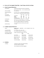
Print Speed
(chars/second)
Chars/inch
Draft
Normal
Correspondence
DP6
DP6
DP7
DP7
10
165
125
32
12
200
150
37
10
12
150
75
180
90
Dot Graphics
DP6: 60, 120, 240 horizontal; 72, 144 vertical
(dots/inch)
DP7: 60,120,180, 360 horizontal; 72, 180 vertical
Feed Speed
50 msec. single line feed at 5 or 6 lines/inch
12 inches/second (305 mm/sec) slew speed
Feed Accuracy
+/- 0.6%
1.2 FORMS CHARACTERISTICS
Media
Single sheets, passbooks, 6 part multipart forms and
envelopes.
Document Width
2.5” (64 mm) to 9.5” (241 mm)
Document Length
2.5” (64 mm) minimum, no maximum
Document Thickness
0.0035” (0.09 mm) to 0.062” (1.57 mm)
Non-printable Areas
DP6
DP7
Top of form
0.25”(6.4mm)
0.16”(4.1mm)
Above horiz. fold
0.25”(6.4mm)
0.38”(9.7mm
Below horiz. fold
0.31”(7.9mm)
0.27”(6.9mm)
Bottom of form
0.40”(10.2mm)
0.45”(11.4mm)
Vertical fold/edge
0.25”(6.4mm)
0.25”(6.4mm)
1.3 RIBBON
Cartridge
Endless loop ribbon with internal reinking
DP6: NEC P2200 compatible
DP7: Panasonic KX-P155 compatible
1
1.4 INTERFACE
Standard Serial
RS-232, DP6: 1200-9600 baud, 4KB buffer
DP7: 2400-19200 baud, 11KB buffer
Optional
RS-232 dual ports or PC parallel port
Command Sets
IBM Proprinter/4722, Unisys and Craden
Protocols
DTR, Xon/Xoff and Block
Power Input
100-130 or 200-260 VAC, 50-60 Hz, 50 W max.
1.5 PHYSICAL CHARACTERISTICS
Dimensions
Width: 14.1” (357mm)
Height: 6.3” (160 mm)
Depth: 10.8” (275 mm) operating, 7.8” (197 mm) standby
Weight
18.3 pounds (8.3 kg) + 3.5 pounds (1.6 kg) packing
1.6 ENVIRONMENTAL & STANDARDS
Operating
10 to 40C, 10 to 90% humidity
Storage
-30 to 70
C, 5 to 95% humidity
Standards
IEC 950, UL 1950, UL File E91899
FCC 20780 Class A certified, Canadian UL Listed
2
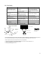
2.0 INSTALLATION
2.1 NORMAL INSTALLATION PROCEDURE
1. Read this section and 3.1 to 3.6 on Operation and Configuration.
2. Remove the cabinet lid and cut the shipping strap that fastens the carriage to the rail on the metal box.
Save the packing material.
3. Install the ribbon cartridge (See 3.3).
4. Check that the label on the printer rear correctly indicates the input supply voltage. (Either 115 VAC for
100-130 VAC input or 230 VAC for 200-260 VAC). If it is incorrect, see Changing Supply Voltage in 2.3.
CAUTION: CONNECTION OF A PRINTER WIRED FOR 115 VAC TO A 230 VAC INPUT CAN
PERMANENTLY DAMAGE THE PRINTER!
5. Check that the power switch on the printer rear is off ("0" side depressed). Connect the line cord to the
printer and then to an electrical outlet. If a suitable line cord was not supplied with the printer, procure an
IEC HAR (harmonized) line cord that has an IEC 320-C13 style connector and the appropriate HAR plug
for your country.
6. Connect and fasten the interface cable to the rear panel connector. (See 3.13.3 for cabling information).
7. Documents longer than 8" will feed out the printer rear. Insure that space is available for the longest
document to be fed.
8. Turn on the power switch located on the rear of the printer. READY should be displayed.
9. Configure the printer by the procedure in 3.6. Default settings are:
LINES/INCH = 6
PROTOCOL = DTR
CHARS/INCH = 10
BAUD RATE = 9600
CHARS = SCRIPT
WORD LENGTH = 8
PRINT = NORMAL
PARITY = NONE
QUIET MODE = N
STOP BITS = 1
DOCUMENT INSERT TOP EDGE
INPUT BUFFER MULTIPLE LINE INSERT WITH 1 SEC
PAUSE
EMULATION MODE C
BEGIN PRINTING IMMEDIATELY
RETURN ON FEED Y
LINE#1 =. 250 IN
In printers with the automatic alignment feature:
SKEW DETECTION CORRECT SKEW
SKEW DETECTION ALLOWED = .050
IF FORM SKEWED ENTER/EJECT KEYS
IF NARROW FORM PROCEED
Common variations are EMULATION MODE I for IBM Proprinter emulation and PROTOCOL = XON/XOF
for software that does not use DTR hardware handshaking. Function 94 settings are factory selected for a
specific printer mechanism and should not usually be changed.
10. Perform a local print test using 95 FUNCT. (See 3.9)
11. If the host is unable to print correctly, check that the Communication Parameters selected under 93
FUNCT match the host parameters and review all Printer Parameters selected under 92 FUNCT.
3
2.2 RESHIPMENT
If possible, retain the original packing material for reshipment. In any event the following precautions must
be observed:
1. Fasten the carriage with a cable tie, string or wire passing around the top of the carriage plate and through
the hole in the front of the guide rail. Insure that the carriage can't move horizontally or vertically.
2. If the original packing material is not used, insure that the cabinet lid will not move during shipment and
that the unit has sufficient protective padding on all sides.
2.3 CHANGING SUPPLY VOLTAGE
The printer can be set to operate with either 115 VAC or 230 VAC input. It will operate from 50 or 60 Hz at
either setting. The label on the back indicates the current setting. To change the voltage setting:
CAUTION: THIS CHANGE MUST BE PERFORMED BY TRAINED SERVICE PERSONNEL
1. Disconnect the line cord from the printer.
2. Remove the screw on the right end of the line cord receptacle and the screw to the left of the power switch.
Slide the power input assembly out of the printer rear.
3. Disconnect the internal power cable from the power input assembly.
4. Use a small blade to depress the locking tab on the side of the green/yellow wire contact and slide the
contact out of the connector. Use the blade to pry the plastic key out of the cable connector.
5. Insert the green/yellow wire contact into the connector position where the key had been and insure that it
locks in place. Insert the key into the connector position where the green/yellow wire had been.
6. Reconnect the internal connector to the power input assembly.
7. CHECK THE CONNECTOR TO THIS CHART. THIS IS IMPORTANT!
Position 1 is the pin closest to the power switch.
Position:
1
115 VAC: Brown
230 VAC: Wht/Blue
2
3
4
Blue
Grn/Yel
Wht/Brn
Grn/Yel
5
6
7
Key
Wht/Brn Key
8
Wht/Blue
Blue
Brown
8. Use a meter to insure there is less than 0.1 ohm resistance from the center blade of the line cord
receptacle and the printer baseplate.
9. Slide the power input assembly back into the printer and fasten it.
10. Replace the fuse and fuse holder with the type indicated on the label on the back corresponding to the new
input voltage.
11. Modify the label on the back to indicate the new supply voltage.
4
3.0 OPERATION
3.1 AUTOMATIC DOCUMENT INSERTION
Insertion procedures may be configured to satisfy varied applications. (See Printer
Parameters in 3.6.1). This description first explains a basic insertion sequence and then
describes variations.
1. Place the document under the clear plastic guide and gently push the left edge of the
document against the edge of the document guide.
2. Slide the document forward until it contacts the feed rollers which will automatically
move the document to the first printable line.
3. Printing can now commence. After printing is complete the document may be ejected.
Step 2 may be configured so that the rollers do not activate for a few seconds or until the
A key is pressed. This allows more time to insert cumbersome documents or to train
new operators.
Printers with the auto alignment feature should be configured for no delay. Documents
should be inserted toward the left edge guide and rollers, then quickly released to allow
them to automatically align. Auto alignment may be disabled for an individual document by
pressing the FUNCT key before insertion. See 3.6.5 to configure auto alignment.
Step 2 may be configured to move the document down to the last (bottommost) printable
line.
Step 3 may be configured to delay printing until the ENTER key is pressed. This allows
the operator to insure that the document has inserted correctly. If not, it may be EJECTed
and reinserted.
3.2 SEMI-AUTOMATIC DOCUMENT INSERTION
If delay printing until the ENTER key is pressed has been configured, the document can be positioned to
begin printing at a specific place:
1. Proceed with steps 1 and 2 of the automatic insertion procedure.
2. Use the A and B keys to align the center of the desired print line with the front edge of the metal guide
above the document.
3. Press the ENTER key. The desired print line will be automatically positioned in front of the printhead and
printing can now begin.
4. After printing is complete the document may be ejected.
When Configuration 12 is selected in 94 FUNCT, pressing ENTER before document insertion allows keypad
entry of the number of lines to be fed before printing begins.
3.3 RIBBON CARTRIDGE LOADING/REPLACEMENT
The DP6 cartridge (Part# 99059) is compatible with the NEC P2200 cartridge. Its drive knob is on the right
side of the cartridge. The DP7 cartridge (Part # 99073) is compatible with the Panasonic KX-P155. Its drive
knob is in the center of the cartridge. The useful life of cartridges from various suppliers may vary greatly and
some may be too heavily reinked for document printing applications. The reinker in some DP7 cartridges
must be manually engaged by removing a clip or pressing a spring when printing becomes light. Do not
engage the reinker until printing becomes light or else printing will become too dark.
5
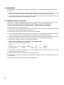
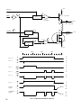
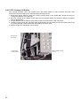
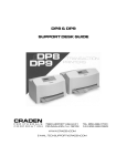
3.3.1 DP6 Ribbon Cartridge Loading/Replacement
To replace a DP6 ribbon cartridge:
1. Remove the lid. If the printer has just finished more than 3 minutes of continuous printing, the printhead
fins may be hot to the touch. Avoid contact with the fins.
2. Press the A and B keys simultaneously to position the printhead nose just to the right of the leftmost
rubber roller segment.
3. Release the old cartridge from the carriage by pulling the release bar on top of the cartridge forward. Lift
the carriage shaft and remove the old cartridge.
4. Rotate the ribbon drive knob until the slot on its bottom side lines up with the ribbon drive tab on the
carriage. Pull a small loop of ribbon from the nose of the cartridge.
5. Lift the carriage shaft with a little finger. Insert the ribbon loop between the bottom of the printhead nose
and slotted plastic ribbon shield and then push the cartridge against the carriage until it snaps into place.
6. Insure that the ribbon is located between the printhead nose and the ribbon shield and the shield is seated
with the notched side toward the rear of the printer. If the ribbon is caught on the front of the printhead
nose use a pen point to push it into place. Rotate the knob on the cartridge clockwise and check that the
ribbon moves correctly.
Release Bar
Ribbon Drive Knob
Printhead Fins
Printhead Attach Screws (2)
Gap Adjust Screws (2)
Printhead Nose
Carriage Shaft
Ribbon Shield
Leftmost Roller
DP6 RIBBON CARTRIDGE LOADING
6
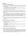
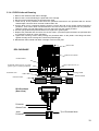
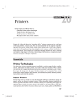
3.3.2 DP7 Ribbon Cartridge Loading/Replacement
To replace a DP7 ribbon cartridge:
1. If the new cartridge has a plastic ribbon shield attached, remove it.
2. Pull about a 1/2" loop of ribbon from the new cartridge.
3. Remove the lid. If several minutes of continuous printing have just been finished, the printhead and
carriage may be hot to the touch. Avoid contact with those parts.
4. Press the A and B keys simultaneously to position the printhead nose between two
segments.
drive roller
5. Lift the carriage shaft with a little finger. Remove the old cartridge by pressing the side clips while pulling
the old cartridge forward.
6. Push the metal ribbon shield downward. Guide the new cartridge's ribbon loop around the pivoting slider
and under the printhead nose.
7. Locate the cartridge tips behind the pivoting slider.
8. Move the cartridge toward the carriage and rotate the cartridge knob counter-clockwise until the cartridge
seats on the carriage plate.
9. Insure that the ribbon lies flat against the printhead nose and that both metal side clips lock onto the
cartridge tabs.
Drive Knob
Side Clips
Printhead Nose
Cartridge Tip
Carriage Shaft
Ribbon Shield
Pivoting Slider
DP7 RIBBON CARTRIDGE LOADING
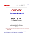
3.4 KEYPAD OPERATION
EJECT: ejects an inserted document if the print buffer is empty.
7
A:
moves a document up 1/60" with each depression. If held depressed, the document will slowly
move into the printer. Also initiates document insertion if the printer is configured for key rather
than automatic insertion. (See 3.6.1)
B:
moves a document down 1/60" with each depression. If held depressed, the document will slowly
move out of the printer .
FUNCT:
enters previously keyed digits as a function code. All function codes beginning with 9 are reserved
for internal printer operations. All other function codes are transmitted to the host system and
their usage is defined by the host. On printers with the auto alignment feature, pressing FUNCT
before document insertion will disable auto alignment for an individual document. See 3.6.5 to
configure auto alignment.
CLEAR:
erases any previously keyed digits before they are transmitted to the host by the FUNCT or
ENTER keys.
ENTER:
transmits previously keyed digits to the host system. All responses are defined by the host. This
key also initiates document printing if the printer is configured to delay printing until the ENTER
key is pressed (See 3.6.1).
0 to 9:
enter digits to be transmitted to the host by the FUNCT or ENTER keys. Key depressions appear
on the lower display line.
KEYPAD
PANEL
1
2
3
4
5
6
7
8
9
& DISPLAY
READY
3.5
EJECT
A
B
FUNCT
CLEAR
0
ENTER
DISPLAY
OPERATION
The
display
consists of 2 lines
of
16
characters
each and is used
to display messages both from the printer and the host system. There is a contrast knob to the left of the
EJECT key that should be adjusted for maximum legibility depending on the display viewing angle. When the
printer is turned on, "READY" will be displayed.
8
3.6 CONFIGURATION
The printer may be completely configured from the keypad with all parameters saved in a non-volatile
memory. There are 4 configuration function codes:
Configuration Category
Printer Parameters
Communication Parameters
Service Parameters
Override Parameters
Press
9 2 then FUNCT
9 3 then FUNCT
9 4 then FUNCT
9 9 then FUNCT
After accessing a category, each parameter will be displayed. Press A to display the next choice for the
parameter or press ENTER to display the next parameter. If the display does not change when A is
pressed, the keypad is locked. See 3.6.4 to unlock the keypad.
3.6.1 Printer Parameters
Press 9 2 then FUNCT to display the following parameters or press 9 0 0 then FUNCT to print them on a
previously inserted document. Changes may be made as described above. Before proceeding, see 3.1-3.2
and select the insertion sequence which best fits your application.
DISPLAY
REMARKS
LINES/INCH = 5 or 6
Select 5 or 6 lines per inch vertical spacing
CHARS/INCH = 10, 12 or 17
Select 10, 12 or 17 characters per inch horizontal spacing.
CHARS = BLOCK or SCRIPT
Select BLOCK or SCRIPT lower case characters in NORMAL mode
(DP6 only).
PRINT = NORMAL, CQ or
DRAFT
Select NORMAL, correspondence quality CQ or high speed DRAFT
(DP6 only) print. Do not use DRAFT on thick forms or passbooks.
QUIET MODE = Y or N
Select Y for reduced noise on thin documents. Select N for darker print
on thick documents.
DOCUMENT INSERT = TOP
or BOTTOM EDGE
Select insertion to the TOP EDGE or the BOTTOM EDGE of the
document.
DOCUMENT INSERT WITH
X SEC PAUSE or WITH A
KEY
Select automatic insertion 0, 1 or 2 seconds after a placing a
document in the input tray or delay insertion until A is pressed to allow
more time for aligning documents.
BEGIN PRINTING
IMMEDIATELY or
AFTER ENTER KEY
Select to begin printing IMMEDIATELY after the document insertion or
delay printing until ENTER is pressed to verify proper alignment.
LINE # 1 = .XXX
Select the distance, between -0.80” and 0.80”, from the document top
edge to the center of the first print line. Select 0.25” unless needing
software compatibility with another printer.
See 3.6.5 for automatic alignment parameters that appear on the Printer Parameter menu.
NOTE: Most Printer Parameters may be configured by the host system via the HT or other commands. This
allows for dynamic reconfiguration on a document by document or line by line basis.
9
3.6.2 Communication Parameters
Press 9 3 then FUNCT to display the following Communication Parameters or press 9 0 0 then FUNCT to
print them on a previously inserted document. Changes may be made as described in 3.6.
10
DISPLAY
REMARKS
INTERFACE PROTOCOL =
BLOCK, DTR, XON/XOF or
PARALLEL INTERFACE
Select the protocol which matches your system configuration (See
3.13). Select PARALLEL if the parallel interface option is installed
& skip the next 4 items.
BAUD RATE = XXXX
Select 1200 (DP6 only), 2400, 4800, 9600 or 19200 (DP7 only)
baud.
WORD LENGTH = 7 or 8
Select 7 or 8 bits/word.
PARITY = XXXX
Select parity bit as EVEN, ODD or NONE.
STOP BITS = 1 or 2
Select 1 or 2 stop bits.
INPUT BUFFER SINGLE LINE or
MULTIPLE LINE
Select a SINGLE LINE or a MULTIPLE LINE buffer of 3K (DP6)
or 11K (DP7).
EMULATION MODE =
C, I, EF4565 or
EF4600/EFP95
Select C to enable commands used with previous versions of this
printer. Other selections enable commands compatible with
popular PC based financial printers .
AUTO CARRIAGE RETURN ON
FEED = Y or N
or
N
Select Y unless compatibility with software written for another
printer is needed.
DUAL PORT = Y or N
Select Y if the dual port option is installed to allow printer sharing
between two hosts. Either DTR or XON/XOF protocol must be
selected.
PAPER OUT = NO DOC or
NEVER
Select NO DOC if the parallel interface is to indicate paper empty
whenever no document is in the printer or NEVER if it is never to
indicate paper empty.
SELECT = DOC PRES or
ALWAYS
Select DOC PRES if the parallel interface is to indicate off-line
whenever no document is in the printer or ALWAYS to always
indicate on-line.
3.6.3 Service Parameters
Press 9 4 then FUNCT to display the following Service Parameters. These parameters are factory selected
specifically for each printer mechanism and recorded on the label next to the display inside the printer. They
do not usually need to be modified by the user.
CAUTION: CHANGE OF THESE PARAMETERS BY UNTRAINED PERSONNEL MAY RESULT IN
INCORRECT PRINTER OPERATION.
DISPLAY
REMARKS
TOP OFFSET = XX
Adjusts the uppermost print line location. Smaller values print
closer to the top document edge.
INDEX OFFSET = XX
Adjusts the distance moved when semi-automatic positioning is
used. Larger values move the print line up the document.
LEFT OFFSET = XX
Adjusts the carriage home location during document insertion.
Larger values move the carriage to the left.
LEFT MARGIN = XX
Adjusts the first column print position. Larger values move printing
to the right.
CAR. ALIGN = XX
Positions lines printed right to left so they align with lines printed left
to right. Larger values move those lines to the left.
FORWARD COMPENSATION
= XX
Adjusts distances moved down the document. Larger values
increase the distance moved between the topmost and bottommost
line.
REVERSE COMPENSATION
= XX
Adjusts distances moved up the document. Larger values increase
the distance moved between the bottommost and topmost line.
EJECT HOLD OFFSET = XX
Adjusts how much of the document is held in the feed rollers after it
is ejected. Lower values hold less of the document.
CONFIGURATION = XX
Selects custom interface options. Select 00 unless indicated
otherwise on the Parameter label or incorrect operation may occur.
GATE OFFSET = XX
Adjusts gate height. Larger values raise gate. (DP7 with Automatic
Alignment feature only)
NORMAL DARKNESS = 0 to
10
Adjusts darkness at normal print speed. Lower values reduce
darkness and increase ribbon life. Select the lowest value that
provides suitable legibility on thick forms (DP7 only).
CQ DARKNESS = 0 to 10
Adjusts CQ print darkness (DP7 only).
11
3.6.4 Override Parameters
Press 9 9 then FUNCT to display the following Override Parameters. Changes should be made only by
trained personnel.
DISPLAY
REMARKS
LOCKED or UNLOCKED
LOCKED allows parameters to be displayed but not changed.
UNLOCKED allows parameters to be changed by the A key.
COVER OVERRIDE OFF or
ON
OFF requires the cabinet lid to be closed for printing to occur. ON
allows trained personnel to print with the lid removed. Replacing the lid
automatically sets the override OFF.
3.6.5 Automatic Alignment Parameters
The following printer parameters may be selected at the end of the Printer Parameter (9 2 FUNCT)
menu on printers with the automatic alignment feature:
DISPLAY
REMARKS
SKEW DETECTION =
CORRECT SKEW, DETECT
SKEW, or IGNORE
select CORRECT SKEW to automatically align skewed documents,
DETECT SKEW to detect but not align skewed documents, or
IGNORE to disable both skew detection and correction.
SKEW DETECTION ALLOWED
= .030, .050, .080, .110 or .130
Select the maximum skew per 4 inches of document width. Treatment
of documents with excess skew is set by the next parameter.
IF
FORM
SKEWED
ENTER/EJECT
KEYS
AUTOMATIC EJECT
= If a document has excess skew, ENTER/ EJECT KEYS will continue
or printing if ENTER is pressed or eject the document if EJECT is
pressed. AUTOMATIC EJECT will always eject a document with
excess skew
IF NARROW FORM =
PROCEED or ENTER/EJECT
KEYS
Documents less than 4.5 inches wide will be detected as skewed.
PROCEED will always accept the document, ENTER/EJECT KEYS will
continue printing if ENTER is pressed or eject the document if EJECT
is pressed.
3.7 DIAGNOSTICS
3.7.1
Power Up Diagnostics
Diagnostic routines are automatically executed during power-up. If a fault is detected, ROM TEST BAD
or RAM TEST BAD may be displayed. If a fault occurs, press A to advance to the next test. However,
the printer should not then be operated. If the problem is not a POWER FAILURE (see 3.10.1), contact
your Service Personnel or see 5.6 of the Technical Manual for troubleshooting.
3.7.2 Enhanced Diagnostics
Diagnostics may be executed by pressing 9 0 then FUNCT. If no faults exist, PROM REVISION XX,
ROM TEST OK and RAM TEST OK will be displayed. If a fault exists, "BAD" will be displayed instead of
"OK" until A is pressed to advance to the next test.
After RAM TEST XXX is displayed, SENSORS LFBC will be displayed. L is the left home carriage sensor; F
and B are the front and back document sensors and C is the cover open sensor. Any sensor that is covered
will have its corresponding indicator erased. Each sensor may be activated to check for proper operation.
Press A to conclude this test.
12
3.8 SELF TEST
A document may be test printed by pressing 9 1 FUNCT. SELF TEST is displayed until a document is
inserted. Then CHAR LENGTH = 30 is displayed. Press A to select CHAR LENGTH = 80. (30 characters
requires a document at least 3 1/2" wide, 80 characters requires 8 1/2".) Do not print across a vertical fold or
document edge. Press ENTER to print the top and bottom lines of the document and then eject it.
3.9 LOCAL PRINTING
In addition to Self Test function 91, it is possible to print several variable length lines without host commands.
Proceed as follows:
1. Insert a form manually or automatically and then press 9 5 FUNCT.
2. In response to CHAR LENGTH = 30, key in a two digit number of characters per line and then press
ENTER. Insure that printing will not occur across a fold or document edge.
3. In response to LINE COUNT = 01, key in a 2 digit number of lines.
4. Each time ENTER is pressed, that number of lines will be printed.
5. Press EJECT to eject the document and CLEAR to clear the display.
3.10 ERROR CONDITIONS
3.10.1 Power Failure
All Configuration Parameters are stored in a non-volatile memory. Power up diagnostics display POWER
FAILURE if an error is detected in that memory. It is now necessary to re-enter the parameters. Press
FUNCT to begin the prompting sequence. The factory set values for the Service Parameters are listed on
the label next to the display inside the printer.
3.10.2 Document Jam
In the unlikely event that a document becomes jammed in the printer, printing will stop and "DOCUMENT
JAM" will be displayed. The operator must clear the jam condition by moving the printhead left as far as
possible and removing the document from the printer.
3.10.3 Cover Open
If the printer lid is removed to replace a ribbon cartridge or clear a document jam, COVER OPEN is displayed
and printing is disabled. Printing will resume 3 seconds after the lid is replaced.
3.10.4 Page Overflow
If the printer is commanded to move past the last printable line on a document it will eject the document and
display PAGE OVERFLOW INSERT NEXT PAGE. Printing will resume when another document is inserted.
3.10.5 Carriage Fault
This message will be displayed if the carriage could not move to the left margin and is probably caused by a
jammed carriage, bad motor driver fuse or a bad left home sensor.
13
3.11 DP6 & DP7 PROGRAMMING
CAUTION: DURING PROGRAM DEVELOPMENT ALL PRINTING SHOULD BE DONE ON SINGLE
SHEET PAPER UNTIL PRINT FIELDS ARE CORRECTLY FORMATTED. PRINTING DIRECTLY ACROSS
THICK FOLDS AND DOCUMENT EDGES CAN DAMAGE THE PRINTHEAD.
The printer accepts two separate command sets, C and I, that are selectable either from the keypad using 9
3 FUNCT (see 3.6.2) or the interface. Mode C is compatible with previous versions of this printer while Mode
I is compatible with popular PC based printers. If Mode I is selected, the DP6 can use a IBM Proprinter driver
and the DP7 can use a IBM Proprinter X24 driver. Unique Mode C commands to communicate with the
keypad/display and request status can still be accessed in Mode I by preceding the Mode C command with a
ESC character.
3.11.1 Mode C Command Summary
Mode C recognizes the following ASCII control sequences:
ASCII
*
*
*
*
*
*
*
STX
ENQ
BEL
BS
HT
LF
VT
FF
CR
SO
SI
DC1/DLE
DC2
DC3/ETB
DC4
EM
SUB
ESC SO
ESC SI
ESC n
ESC A
ESC B
ESC E
ESC F
ESC J n
ESC ]
ESC ~ I
FS
GS
RS n
US
Hex
02
05
07
08
09
0A
0B
0C
0D
0E
0F
11/10
12
13/17
14
19
1A
1B 0E
1B 0F
1B 3#
1B 41
1B 42
1B 45
1B 46
1B 4A
1B 5D
1B 7E 49
1C
1D
1E n
1F
Command
Start envelope data
Status request
Load upper display immediate
Reverse line feed
Configuration download
Line feed
Vertical tab feed
Eject document
Print buffer
Begin expanded characters
End expanded characters
Key buffer request
Line count request
Load upper display delayed
Master reset
Document length request
Status request delayed
Begin double height characters
End double height characters
Feed document up #/120 inches
Begin 60 dot/inch graphics
Begin 120 dot/inch graphics
Begin bold print
End bold print
Feed document up n/216 inches
Reverse line feed
Select Mode I
Load lower display immediate
Load lower display delayed
Skip n blank spaces in print line
Begin/End underscore
Commands prefixed with a * will not be executed until after an ENQ is received if the BLOCK protocol is
used. ENQs are not required if DTR or XON/XOF protocols are used.
14
3.11.2 Mode C Document Movement Commands
BS
or ESC ] moves the document down one line, with line spacing keypad selected (see
3.6.1) or set by an HT command.
LF
moves the document up one line, with line spacing keypad selected (see 3.6.1) or set by
an HT command.
VT n
moves the document a variable number of lines or steps with n being a single byte, bit
coded as 01ULCCCC where:
U = 1 = Up feed
U = 0 = Down feed
L = 1 = Line feed (1/6” or 1/5”)
L = 0 = Step feed (1/60”)
CCCC = Line count or step count
moves the document up (CCCC)/120 inches where n is a single byte bit coded as
0011CCCC.
ESC n
ESC J n
moves the document up n/216 inches where n is a single binary coded byte.
FF
ejects the document.
If any document movement command (BS, LF, VT, ESC n, ESC ], ESC J n or FF) has been preceded by any
printable ASCII characters, they will be printed before the movement command is executed.
3.11.3 Mode C Print Commands
CR
prints all preceding printable ASCII characters. There is no document movement due to the
CR.
SO
starts double width printing. All characters received after an SO and before an SI, CR or
feed command will be printed double width.
SI
stops double width character printing.
ESC SO
starts double height printing. All characters received after an ESC SO and before an ESC SI,
CR or feed command will be printed double height. Single height characters will be printed in
line with the top of double height characters if they are mixed in a print line.
ESC SI
stops double height printing.
ESC E
starts bold, double strike printing in 10 and 12 character/inch NORMAL print speed and
reduces print speed by 33% (DP6) or 50% (DP7).
ESC F
stops bold printing.
RS n
inserts n blank spaces into the print line and can be used to reduce the number of
characters transmitted when large blank spaces are to be printed. n is of the form
01NNNNNN where NNNNNN is the number of blanks to be inserted. RS A is 1 blank, RS z
is 58.
US
enables or disables underscoring of printable characters. All characters received after a US
and before another US, CR or feed command will be printed with the character underscored.
STX
prints envelopes. It must be immediately followed by two bytes, X and Y, each bit coded as
01NNNNNN. NNNNNN/10 inches is the distance from the top edge of the envelope to the first
line of text for X and from the left edge of the envelope to the first column of text for Y.
Following X and Y are normal lines of text separated by LF's and finally terminated by a FF
which causes printing and ejection.
DC4
clears all previously received data out of the buffer.
15
3.11.4 Mode C Display Commands
BEL
immediately displays the following 16 characters on the upper line of the alphanumeric
display. The characters must not be control characters and there must be exactly 16
displayable characters.
FS
loads the lower display line just like BEL loads the upper line.
DC3
or ETB operate identically to a BEL command but all previously received print and
document movement commands are executed before the upper line of the display is
loaded.
GS
loads the lower display line just like DC3 loads the upper line.
3.11.5 Mode C Configuration Commands
HT
changes the machine configuration and must be followed by 2 characters of the form
01PVHFCS and 01LEIBDQ where:
P = 1: Permanent configuration change.
0: Change just for one document
V = 1: 5 lines/inch vertical spacing
0: 6 lines/inch vertical spacing
H = 1: 12 characters/inch horizontal spacing if S=0
0: 10 characters/inch horizontal spacing if S=0
F = 1: Script lower case
0: Block lower case
C = 1: Correspondence quality print if S=0
0: Normal print if D = 0
S = 1: 17 characters/inch horizontal spacing
0: Horizontal spacing determined by H bit
L = 1: Lock keypad from modifying set up parameters
0: Unlock keypad for modifying set up parameters
E = 1: Document present set by ENTER key after insertion
0: Document present set automatically after insertion
I = 1: Insertion initiated by DOWN key
0: Start insert _ seconds after document sensed in chute
B = 1: Insertion to bottom edge
0: Insertion to top edge
D = 1: Draft print (do not use on thick documents) if C=0
0: Print mode determined by C bit
Q = 1: Quieter print on thin documents
0: Darker print on thick documents
All parameters configurable by an HT are also programmable from the keypad. See 3.6.1.
ESC ~ I
16
clears all previously received data out of the buffer and switches the interface to Mode I.
3.11.6 Mode C Status and Keypad Commands
Status, key buffer contents, line count or document length data are transmitted when requested by the host.
ENQ
requests printer status and is executed when it is received.
SUB
also requests printer status but it is executed identically to an ENQ only after all previously
received commands have been executed. SUB may be used to interrupt the host and notify it
that the printer is now idle.
Printer status is a single byte that is bit significant as follows:
0 1 DP XE DJ KB BZ BA
DP = Document present. Set whenever a document is in the feed path.
XE = Transmission error. If BLOCK protocol is used, all characters received since the last ENQ will be
ignored and should be retransmitted. If DTR or XON/XOF protocols are used the character
associated with the error will be printed as a “@”.
DJ =
Document jam. The printhead has not returned to the document edge correctly and operator attention
is required.
KB = Key buffer. The key buffer contains key stroke information that will be transmitted upon receipt of a
DC1.
BZ = Busy. Either printing or document movement is now occurring.
BA = Input buffer available. At least 1000 characters of space are available in the input buffer or the buffer
is empty. Buffer operation is detailed in 3.13.1.
DC1
or DLE request keypad data. Upon receipt of either, all keypad input that has been pressed since the
previous DC1 or DLE will be transmitted. A maximum of 16 strokes can be buffered. Transmitted
characters will be one of the following:
ASCII
0-9
:
;
<
=
?
Meaning
Numeric keys 0-9
FUNCTion key
ENTER key
Either A or B key
EJECT key
End of buffer
The last character transmitted is always a ?. If a DC1 or DLE is received and no keys have been
pressed only a ? will be transmitted.
As numeric keys are pressed, their values are displayed on the lower display line. Pressing ENTER or
FUNCT transfers the key strokes to the key buffer. Pressing CLEAR deletes numeric key strokes
before they are transferred to the key buffer.
Function values beginning with 9 are reserved for internal printer operation and are not transferred to
the key buffer. See 3.6 to 3.9 for details of the internal printer functions.
DC2
requests line count information. Upon receipt, 2 bytes are transmitted. The first byte indicates the
number of lines and the second indicates the number of additional 1/60” steps moved since the
document was initially registered at top edge or bottom edge.
EM
requests document length information. Upon receipt, 2 bytes representing the document length (if the
document was automatically inserted to the bottom edge) are transmitted. The first byte indicates the
number of lines and the second byte indicates the number of additional 1/60 inch steps.
17
3.11.7 Mode C Graphics Commands
Dot addressable graphics may be printed at 60 or 120 dots/inch (dpi) horizontally by 72 or 144 dpi vertically.
ESC A must precede each line of 60 dpi data with a maximum of 480 data bytes. ESC B must precede each
line of 120 dpi data with a maximum of 960 bytes. Each line of data must be terminated by a feed command,
usually a VT e, ESC 1 or ESC 9.
Each data byte is of the form 1ABCDEF where A is the lowest and F is the highest of 6 vertical dots printed in
a single dot column. Each bit must be set to a 1 for the corresponding dot to be printed.
VT e moves a document up 5/60 inch and positions it for printing contiguous rows of graphics since 5/60 is
the same height as 6/72. The RS command is useful for filling multiple blank dot columns. For example, the
following sequence will print a diagonal line starting in the upper left corner of column 1 and slanting down to
the right:
ASCII
ESC A A B D H P ` VT e
ESC A RS F A B D H P ` VT e
ESC A RS L A B D H P ` VT e
Hex
1B 41 41 42 44 48 50 60 0B 65
1B 41 1E 46 41 42 44 48 50 60 0B 65
1B 41 1E 4C 41 42 44 48 50 60 0B 65
ESC 1 feeds a document up 1/120 inch or about one half dot height. Graphics can be printed at a vertical
density of 144 dpi by using ESC 1 but the host must interleave the data. Each line of data must contain dot
data for every other row of dots to be printed. After an ESC 1 and the next line of dot data, an ESC 9 moves
the document 9/120 inch and positions it for printing the next contiguous row of dots.
Assuming full width lines, graphics throughput is 18 seconds/inch for 60 by 72 dpi and 22 seconds/inch for
120 by 72 dpi. Speed is halved when printing 144 dpi vertically
18
3.12.1 Mode I Command Summary
Mode I recognizes the following ASCII control sequences:
ASCII
Hex
Command
* BS
HT
* LF
* VT
* FF
* CR
SO
SI
DC2
DC4
CAN
ESC - n
ESC 0
ESC 1
ESC 2
ESC 3 n
ESC 4
ESC 5 n
ESC :
ESC A n
ESC B
08
09
0A
0B
0C
0D
0E
0F
12
14
18
1B 2D n
1B 30
1B 31
1B 32
1B 33 n
1B 34
1B 35 n
1B 3A
1B 41 n
1B 42
Print the buffer and backspace one character
Move the print pointer to the next horizontal tab
Line feed
Move the document to the next vertical tab
Eject the document
Print the buffer
Begin expanded characters
Begin 17.1 character/inch printing
Begin 10 character/inch printing
End expanded characters
Clear the print buffer
Begin (n=1) or end (n=0) underscore
Set 1/8 inch line spacing
Set 7/72 inch line spacing
Set line spacing stored by prior ESC A
Set n/216 inch line spacing
Eject the document
Begin (n=1) or end (n=0) automatic LF after CR
Begin 12 character/inch printing
Store n/72 inch line spacing
Set vertical tab stops
ESC D
ESC E
ESC F
ESC G
ESC H
ESC I n
* ESC J n
ESC K
ESC L
ESC R
ESC W n
ESC X mn
ESC Y
ESC Z
ESC [ @
ESC [ I
ESC [ J
ESC [ d
ESC [ g
* ESC ]
ESC d
ESC ~ C
ESC XXX
1B 44
1B 45
1B 46
1B 47
1B 48
1B 49 n
1B 4A n
1B 4B
1B 4C
1B 52
1B 57 n
1B 58
1B 59
1B 5A
1B 5B 40
1B 5B 49
1B 5B 4A
1B 5B 64
1B 5B 67
1B 5D
1B 64
1B 7E 43
1B XXX
Set horizontal tab stops
Begin bold print
End bold print
Begin correspondence quality (CQ) print
End correspondence quality print
Begin CQ (n=2) or normal (n=0) print
Feed document up n/216 inches
Begin 60 dot/inch graphics
Begin 120 dot/inch graphics
Set all tabs to default values
Begin (n=1) or end (n=0) expanded chars
Set left and right margins at columns m and n
Begin 120 dot/inch full speed graphics
Begin 240 dot/inch graphics
Begin or end double high or wide
Set character pitch
Set 1/5 inch line spacing
Set print quality
Set graphics mode (DP7 only)
Reverse line feed
Move print position
Select Mode C
Execute Mode C command XXX
19
Commands prefixed with a * will not be executed until after an ESC ENQ is received if the BLOCK protocol is
used. ESC ENQ's are not required if DTR or XON/XOF protocols are used.
3.12.2 Mode I Document Movement Commands
LF
moves the document up one line, with line spacing keypad selected (see 3.6.1) or set by an ESC
0,1,2 or 3 command.
ESC 0
sets line spacing to 1/8 inch.
ESC 1
sets line spacing to 7/72 inch.
ESC 2
sets line spacing stored by a prior ESC A n.
ESC 3 n
sets line spacing to n/216 inch with n being a single binary coded byte.
ESC 5 n
sets auto LF if n=1 and resets it if n=0. A line feed is automatically performed when a CR is
received if auto LF is set.
ESC A n
stores lines spacing of n/72 inch with n being a single binary coded byte but the stored line
spacing will not begin until it is set by an ESC 2.
ESC [ J
followed by the 4 byte hexadecimal sequence 02 00 20 01 sets line spacing to 1/5 inch.
VT
moves the document up to the next vertical tab stop or does a LF if no tab stops are set.
ESC B
nnnnn0 sets up to 64 vertical tab stops at each line n with each n being a single binary coded
byte and terminating with a 0 byte. ESC B 0 clears all vertical tab stops.
ESC R
clears all vertical tabs and sets horizontal tabs to default values of column 9 and every eighth
column to the right.
ESC J n
moves the document up n/216 inches with n being a single binary coded byte.
ESC ]
moves the document down one line, with line spacing keypad selected (see 3.6.1) or set by an
ESC 0,1,2 or 3 command.
FF
or ESC 4 ejects the document.
If any document movement command (LF, VT, FF, ESC 4, ESC J # or ESC ]) has been preceded by any
printable ASCII characters, they will be printed before the movement command is executed.
3.12.3 Mode I Print Commands
20
CR
prints all preceding printable ASCII characters. There is no document movement due to the CR
unless auto LF has been set by a ESC 5 01 command and then a LF will be performed.
BS
prints all preceding printable ASCII characters and positions the print pointer so the next
character will be printed over the last character.
HT
moves the print pointer to the next horizontal tab to the right if one is set.
ESC D
nnnnn0 sets up to 28 horizontal tab stops at each column n with each n being a single binary
coded byte and terminating with a 0 byte. ESC D 0 clears all horizontal tab stops.
ESC R
sets all horizontal tabs to default values of column 9 and every eighth column to the right and
clears all vertical tabs.
ESC d
mn moves the next print position right by (256 X n + m)/120".
ESC X
mn sets the left and right margins at columns m and n. Printing will then begin at column m and
can not extend past column n.
SO
starts double width printing. All characters received after an SO and before a CR, DC4, CAN,
ESC W or feed command will be printed double width.
DC4
stops double width character printing.
ESC W n
starts double width printing if n=1 and stops it if n=0.
ESC [ @
followed by 04 00 00 00 m n hex selects double high and wide print. Double high print is set if the
low order nibble of m is 2 and single high is set if it is 1. Double line feeding is set if the upper
nibble of m is 2 and single line feeding is set if it is 1. Double wide print is set if n is 2 and single
wide is set if it is 1.
ESC :
starts 12 character/inch printing.
SI
starts 17.1 character/inch printing.
DC2
stops 12 or 17.1 character/inch printing and returns to 10 cpi.
ESC E
starts bold, double strike printing in 10 or 12 character/inch.
ESC F
stops bold printing.
ESC G
starts correspondence quality printing.
ESC H
stops correspondence quality printing.
ESC I n
starts correspondence quality printing if n=2 and stops it if n=0.
ESC [ F
followed by 00 02 n1 n2 selects skew control as follows
n 1 n2 = 03 00
no skew detection
01 00
0.05 in. allowable skew
01 01
0.08 in. allowable skew
01 02
0.11 in. allowable skew
01 03
0.13 in. allowable skew
ESC [ I
followed by 02 00 m n hex selects print pitches as follows:
10 cpi if m n = 00 0B, 00 0C, 00 24, 00 19, 00 05 or 01 D4
12 cpi if m = 01 and n = EB, EF, 8F, D0, CB or D5
17 cpi if m = 01 and n = ED, C9, 8D, D2, CD or D7
20 cpi if m = 01 and n = EE, CA, 8C, D3, CE or D8
24 cpi if m = 01 and n = 1E, 1F, 20, 23, 21 or 24
ESC - n
starts continuous underscoring if n=1 and stops it if n=0.
ESC [ d
followed by 01 00 n hex sets print quality to normal if n is between 1 and 127, to CQ if n is
between 128 and 254, or to default if n is 255. No change occurs if n is 0.
CAN
clears all previously received data out of the buffer.
ESC~C
clears all previously received data out of the buffer and switches the interface to Mode C.
ESC XXX will execute Mode C command XXX. This allows access to Mode C commands that have no
equivalent in Mode I for loading the alphanumeric display, requesting keypad input, printing
double height characters and checking status. ESC XXX should not be used for Mode C
commands other than ENQ, BEL, DC1/DLE, DC3/ETB, SUB, ESC SO, ESC SI, FS and GS.
3.12.4 Mode I Graphics Commands
DP6 dot addressable graphics may be printed at 60, 120 or 240 dots/inch (dpi) horizontally by 72 dpi
vertically. ESC K sets 60 dpi, ESC L or ESC Y set 120 dpi and ESC Z sets 240 dpi. ESC Y prints at full speed
but consecutive horizontal dots are prohibited. ESC L prints slower without this restriction. Each command is
immediately followed by m and n, a 2 byte data count indicating that the number of following graphic data
bytes is m + 256 X n. The maximum data count is 480 for ESC K, 960 for ESC L or ESC Y and 1920 for ESC
Z.
Each data byte is of the bit form ABCDEFGH where A is the highest and H is the lowest of 8 vertical dots
printed in a single dot column. Each bit must be set to a 1 for the corresponding dot to be printed.
ESC 3 followed by a 24 byte sets line spacing for printing contiguous rows of graphics since 24/216 is the
same height as 8/72. The following hex sequence will then print a diagonal line starting in the upper left
corner of column 1 and slanting down to the right:
1B 4B 08 00 80 40 20 10 08 04 02 01 0A
21
1B 4B 10 00 00 00 00 00 00 00 00 00 80 40 20 10 08 04 02 01 0A
The DP7 accepts ESC K, L and Y commands. These and other graphics modes are also selected by an ESC
[ g m n p where m + 256 X n is the following graphics data byte count plus one and p selects graphics
densities as follows:
p value:
0
Density: 60x72
1
2
120x72
120x72
8
60x180
9
120x180
11
180x180
12
360x180
In the 180 dpi vertical modes, each group of 3 following graphics data bytes will be printed as one 24 dot
vertical stroke.
3.13 COMMUNICATIONS INTERFACE
The standard interface provides for RS-232 asynchronous serial communications at 1200 (DP6 only), 2400,
4800, 9600 or 19200 (DP7 only) baud and has a multiple line input buffer. Characters may contain either 7 or
8 data bits, even, odd or no parity and 1 or 2 stop bits. These parameters are all keypad programmable. See
3.13.4 and 3.13.5 for Dual Port and Parallel interfaces.
3.13.1 Input Buffer Operation
All commands and characters received except immediate status requests, display and reset commands are
placed in a first-in, first-out input buffer of 3K (DP6) or 11K (DP7) bytes. The BA status bit indicates at least
1000 characters of unused buffer are available. Transmission to the printer should be block structured (less
than 1000 characters per block) with ENQs issued at the end of each block to check for transmission errors
in the preceding block (requiring retransmission) and buffer availability for the next block. ENQs are not
required for blocking data if DTR or XON/XOF protocols are selected from the keypad but these protocols do
not allow for detection of transmission errors. Characters with transmission errors will be replaced by a "@"
under those protocols.
The input buffer can receive the next line of data while the previous one is being printed. This eliminates
transmission induced delays in printing. For this mode of operation SINGLE LINE INPUT BUFFER should be
selected from the keypad and BA indicates an empty buffer.
The buffer may also be used to receive all commands for printing an entire document. In this mode of
operation the full 3K or 11K byte buffer is utilized and BA indicates at least 1000 characters of unused buffer
space. This technique can reduce host attention to the printer but caution must be used to determine correct
recovery from document jams and operator intervention during printing.
In the unlikely event that a document should become jammed in the printer, printing will stop and
"DOCUMENT JAM" will be displayed. The next status word requested by the host will have the document jam
bit set. Once notified, the host may prompt the operator by writing recovery instructions to the display.
As part of the recovery procedure, the host may require all previously transmitted data to be destroyed. This
might be the case if the transaction must be restarted. Previously transmitted data can be destroyed if the
host transmits a DC4 in mode C or a CAN in mode I. After the operator has cleared the jam condition by
moving the printhead to the left wall and removing the document, all data in the FIFO will be destroyed. The
host should request status and check the document jam bit in the status word before retransmitting data.
The operator may also destroy the contents of the FIFO buffer if, after removing the document and moving
the printhead to the left wall, the CLEAR key is depressed. The host must then be notified by the operator
that the transaction data must be re-transmitted.
3.13.2 Interface Protocols
If the BLOCK protocol is used, ENQs must be issued to block data and the returned printer status byte should
be examined by the host to check for transmission errors that require retransmission of the last block.
If host software cannot support the BLOCK protocol, either DTR or XON/XOF protocols may be selected
from the keypad. In these modes the DTR signal will go false (negative voltage) or a DC3 (Xmit off) will be
transmitted if less than 1000 characters of space are available in the buffer when a CR or document
22
movement command is received. Transmission from the host must then pause. DTR will later go true
(positive voltage) or a DC1 (Xmit on) will be transmitted when space becomes available and host
transmission may resume. DTR is equivalent to most operating systems’ hardware protocol.
Under the DTR and XON/XOF protocols ENQ will still generate the normal status response but it is not
necessary to transmit ENQs in order to cause command execution. However, if ENQ and DC1 are never
issued and status responses are never examined by the host, it is difficult to use the keypad for system input.
3.13.3 Interface Signals
The interface provides for RS-232 communication. All signals are available on a 25 pin male connector
equivalent to Cinch DB-25P. If the Dual Port option is installed there will be two identical 25 pin male
connectors. All connectors have 4-40 threaded inserts for positive mating. Pin assignments are as follows:
Pin Signal
Description
1
Protective ground
Attached to printer frame.
2
Transmit Data (TD)
From printer, transmits printer status.
3
Receive Data (RD)
To printer, receives data & commands.
4
Request To Send (RTS)
From printer, indicates printer is ready to transmit
5
Clear To send (CTS)
To printer, enables status transmission.
6
Data Set Ready (DSR)
To printer, enables printer to receive data and commands.
7
Signal ground
Attached to printer logic ground.
20 Data Terminal Ready (DTR)
From printer, indicates printer is ready to communicate. Also
indicates input buffer available if DTR protocol is selected.
Note that regardless which interface is used DSR must be active for the printer to receive commands and
CTS must also be active for the printer to transmit status. If no connection is made to these signals, they are
biased active in the printer.
The following cable connection will work correctly in most applications using PC type 25 or 9 pin serial ports.
A shielded cable with only one end of the shield connected to a metal connector cover or pin 1 of a 25 pin
connector is recommended to increase immunity to static discharges and other electrical noise.
Manufacturer’s part number is 72118-1 for a 9 pin PC cable.
Printer Pin
PC-25 Pin
3
2
20
7
PC-9 Pin
2
3
5
6,20
7
3
2
8
4,6
5
Signal
Data to Printer
Data from Printer
DTR to PC CTS
PC DTR to PC DSR
Signal Ground
Some applications (Online, Microbilt, Bisys, Intrieve) check DSR rather than CTS for printer status. Use the
following cable with such software. Manufacturer’s part numbers are 72100-1 for a 9 pin PC cable and
72098-1 for a 25 pin PC cable.
Printer Pin
3
2
20
7
PC-25 Pin
PC-9 Pin
2
3
5,6
6,8
7
Signal
3
Data to Printer
2
Data from Printer
DTR to PC CTS & DSR
5
Signal Ground
23
3.13.4 Dual Port Option
The Dual Port option allows for simultaneous connection to two hosts with each one alternately enabled using
either the DTR or XON/XOF protocols. A port is enabled for 0.25 seconds or, if data is received, until no
document is present and the buffer is empty. If configuration 05 is selected under 94 FUNCT, the display will
show which port received data.
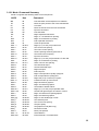
3.13.5 Parallel Interface Option
A PC type parallel interface is optionally available. This interface accepts all commands defined in 3.11 or
3.12 but does not accept status, key buffer, line count or document length requests since data cannot be
transmitted back to the host through this unidirectional interface. All signals are available on a 36 pin female
connector. A shielded cable with only the PC end of the shield connected to a metal connector cover is
recommended to increase immunity to static discharges and other electrical noise. Pin assignments are as
follows:
Pin
1
2 to 9
10
11
12
24
Signal
Strobe(-)
Data Bits 0 to 7
Acknowledge(-)
Busy
Paper Empty
Pin
Signal
13
Select
32
Error(-)
35
+5 Volts
18 to 25 Logic ground
4.0 THEORY OF OPERATION
4.1
OVERVIEW
The DP6 & DP7 Document Printers handle and print a large variety of documents. The mechanism consists
of a printhead, a printhead drive assembly and a document drive assembly. The electronics consist of an AC
PCB (printed circuit board), a power transformer, a Main PCB, two sensor assemblies and a keypad/display
assembly.
4.1.1 Printhead Drive Assembly
The printhead drive assembly positions the printhead as it prints each line of characters. The printhead and
ribbon drive mechanism are mounted on a moveable carriage which is supported by a carriage shaft. The
carriage shaft is mounted to two pivot arms that allow the carriage to lift away from the platen and
accommodate different thickness documents. The carriage is lifted by a slider that rides across the document
surface and maintains a constant printhead to document gap, thereby maintaining print quality across a wide
document thickness range. A guide wheel mounted on the carriage rides across the front of the metal box and
stops the carriage from rotating around the carriage shaft.
A toothed belt clamped to the carriage is driven by a toothed pulley mounted on the carriage stepper motor
located on the right side of the metal box. The stepper motor moves the printhead in 1/120th of an inch
increments along the print line. Position information is maintained by the electronics and updated when a flag
on the carriage interrupts the optical slot sensor mounted to the left pivot arm.
The ribbon cartridge is driven by a shaft on which two pulleys with internal one-way clutches are mounted. A
spring tensioned steel cable mounted between the pivot arms rotates both pulleys as the carriage traverses
and the clutches are oriented so the shaft is rotated clockwise by the rear pulley when the carriage is moving
to the right and by the front pulley when the carriage is moving to the left.
4.1.2 Document Drive Assembly
The document drive assembly positions inserted documents. The document drive stepper motor mounted on
the left side of the metal box is connected to the two drive rollers through toothed belts. A pinch roller is
spring loaded against each drive roller providing friction feed for documents of varying thickness. Documents
are fed between the drive and pinch rollers, with the spring loaded pinch roller automatically adjusting to the
document thickness. The stepper motor positions in 1/120th of an inch increments.
The presence of a document in the input tray is sensed by the first of two optical slot sensors located along
the left edge of the document path. The second sensor is used during document insertion for positioning to
the top or bottom edge of the document.
Printers with the auto alignment feature have a gate that is raised across the document path during document
insertion. At that time the printhead moves past its normal right home position, activating an arm that raises
the gate. The rising gate reduces the spring loading force on the front document drive rollers, allowing
documents to rotate and align against the gate. A third optical sensor, in line with the second sensor, checks
the leading document edge to insure that both sense the leading document edge within a programmable
alignment tolerance. After alignment is verified, the printhead moves to the left, lowering the gate out of the
document path and restoring normal loading force to the document drive rollers.
4.1.3 AC Printed Circuit Board and Power Transformer
The AC PCB is located under the rear of the document drive and contains a line filter, line fuse and line
switch. It provides AC to the power transformer located inside the metal box. The transformer converts 115 or
230 VAC to center tapped 48 VAC with the center tap connected to both chassis and signal ground.
4.1.4 Main Printed Circuit Board
The Main PCB is located in the rear of the printer and contains power supply, control and driver electronics.
The center-tapped 48VAC from the power transformer is converted to unregulated +30 to 40VDC,
25
semiregulated +/-12VDC and switching regulated +5VDC on the main PCB. The unregulated +30 to 40VDC
drives the printhead and stepper motors. The DP6 also develops unregulated -30 to -40VDC to drive the
printhead.
The control electronics are based on a 6809 microprocessor, a 64 Kbyte EPROM, an 8K (DP6) or 32K (DP7)
byte RAM, a 6522 I/O & timer device and an 8251 serial I/O communication device. The main PCB also
contains circuitry for interfacing to the keyboard/display assembly, driving the printhead and stepper motors
and providing signal level conversion for the serial interface signals. The driver electronics include switching
transistors that drive the printhead and 4 H-Bridge switching regulators that drive the carriage and document
drive stepper motors.
4.1.5 Keypad/Display Assembly
The keyboard/display assembly consists of a 16 key keypad arranged in a 4 x 4 scanning matrix and a 2 line
by 16 character dot matrix LCD display module. The display buffers 32 characters of data and generates the
dot patterns and timing to drive the LCD. The keypad assembly also contains an optical slot sensor that
detects removal of the cabinet lid.
4.2
ELECTRONICS IN DETAIL - Refer to #72080 (#72115 for DP7) Schematic
The following sections describe the DP6 with DP7 differences described in parentheses.
4.2.1 Power Supply
The center-tapped 48VAC supplied from the power transformer is converted to unregulated +/-30VDC (+30
only in DP7) by diode bridge D3 to 6 (half bridge D3 & D4) and filter capacitors C18 and C19 (C22). The
printhead is driven from +/-30VDC (+30 VDC only) and the stepper motors are driven from +30 VDC
protected by a 0.75A fuse F1. Semiregulated +12VDC is generated from +30VDC by bleeder resistor divider
R44 & 45 (R36 & 37) and linear regulator Q14 (Q31). In the DP6 semiregulated -12VDC is generated from 30VDC by bleeder resistor divider R38 & 39 and linear regulator Q13. (In the DP7 semiregulated -12VDC is
generated from +12VDC by a 7662 switching inverter U10.) +5VDC to power the logic is generated from +30
VDC by switching regulator Q15 (Q35) using Schottky diode D20 (D37) and output filter L1,C31 (C36). The
100KHz switching frequency is set by C29 & R51 (C25 & R41).
The 48VAC input charges up C6 (C35) through D1,D2 and R1 (R40). The C6 (C35) voltage is monitored by
precision reference Q1 (Q33) to insure correct operating voltages during power-up and power-down. Q1
(Q33) provides a PWROK signal through Q2 (Q34) to the microprocessor and an enable signal to the device
decoding logic.
4.2.2 Microprocessor System
The 6809 microprocessor U23 (U26 in DP7) has a 1.0 (0.5) microsecond cycle time which it generates from
4MHz (8mhz) crystal Y1. Once each cycle the 6809 provides a timing pulse on U23 (U26) pin 34 for
synchronizing the devices on the data bus and updates the address information on pins A0-A15. The high
order address lines are decoded by a 74HC139 U11 (PAL U13). The decoded outputs are utilized as chip
selects to the RAM, EPROM and other LSI devices so that the corresponding device can be read or written to
by the 6809.
In the DP6 the 8 KByte RAM U21 is selected by U11 pin 6 when A15, 14 & 13 are all low. (In the DP7 the 32
Kbyte U25 is selected by U13 pin 16 when A15 is low unless A14 & 13 are both high and any bank select line
BNK1 to 3 is low which selects EPROM or unless A14,12 & 11 are low and A13 is high which selects I/O
devices.) The RAM provides work space and buffer memory for the 6809. All printer, communication and
service configuration parameters are also stored in the RAM which is powered by a 3 Volt lithium battery when
AC power is turned off. (Later versions of the DP6 and the DP7 uses serial EEPROM (U15A DP6; U11 DP7)
to store parameters and have no battery.)
26
In the DP6 the 64 KByte EPROM U22 is selected by U25 pin 10 whenever either A14 or A15 is high, allowing
48 Kbytes of addressable EPROM. (In the DP7 the 64 or 128 KByte EPROM U24 is selected by U13 pin 19
whenever either A15 is high or any bank select BNK1 to 3 is low, allowing 64 or 88 Kbytes of addressable
EPROM.) The EPROM contains the dot patterns for all printable characters and all programs that the 6809
executes to control the printer.
The 8251 serial communication controller U24 (U27) is selected by U11 pin 9 (U13 pin 14) and receives and
transmits asynchronous serial data. Baud rate, word length, parity and number of stop bits are programmed
into the 8251 from the keypad. The baud rate clock for the 8251 is generated by a 74LS161 binary counter
U16 (U19) that provides one clock pulse for every thirteen E pulses provided by the 6809. RS-232 interface
signals are level-shifted by receiver U13 (U15) and driver U8 (U9). Two OR gates U12 (U14) control dual port
mode transmission.
The 6522 I/O & Timer device U20 (U23) is selected by U11 pin 10 (U13 pin 18) and contains two 8 bit output
ports, 4 control lines and 2 programmable timers. Port A controls the document stepper motor and Port B
controls the carriage stepper motor. Stepper motor timing and printhead print pulse length are controlled by
the 2 timers.
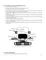
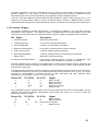
4.2.3 Stepper Motor Drivers
Each stepper motor has 2 stator coils, each driven by a 3717 driver U1 to U4. Each 3717 contains 4
transistors arranged in a H-Bridge that can apply +30 VDC to either end of the coil, a 25KHz switching
oscillator and comparators that limit the coil current by sensing the voltage on an external resistor R4,7,13 or
18 (R2,6,15 or 18). Each 3717 is controlled by 3 signals that are latched in the 6522: a phase signal which
indicates which direction current is to flow through the coil and two signals which limit the current to 0,20,60 or
100% of a maximum value determined by the external resistor. 0% is used to turn off a winding, 20% is used
when the motor is holding a fixed position and 100% is used when the motor is rotating. See Figure 4-1 for
typical voltage waveforms on both ends of a motor coil and the external resistor. The ground plane under the
4 3717's is connected to a finned heat sink to reduce the temperature rise. Both stepper motor drivers are
protected by a single 0.75A fuse F1.
27
+30V
A
Phase
3717
I 0 current
Current
Control
I 1 current
Phase
Control
D
C
VREF
Comp.
One
Shot
B
R4 Typ
0
U20 - 15
2.7 mSec
5.5 mSec
5v
A
0v
0.4v
R4
B
J2 - 1
C
0.0v
30v
0v
30v
J2 – 3
D
0v
FIG 4.1 STEPPER MOTOR DRIVE CIRCUIT
28
Motor rotation occurs by sequentially changing the phase and current signals to the two motor coils. Motor
speed is controlled by how rapidly the signals are changed. Following is a state table where each state
change rotates the document motor rotor 1/400 of a revolution (1/120" of document motion) and there are 8
distinct states before the pattern repeats. Direction of motor rotation can be reversed by moving up rather
than down through the state table. The 2 motor windings are labeled Phase A and Phase B and the phase
and 2 current level signals for each winding are shown. The state table for the carriage motor is similar but the
states with 0% current are skipped so each state change rotates the carriage motor rotor 1/200 of a revolution
(1/120" of carriage motion).
Phase A I0A I1A Phase B I0B I1B
1
1
1
0
0
0
0
1
0
0
0
1
0
0
0
1
0
0
0
1
0
0
0
1
1
0
0
0
0
1
1
1
A Current
0
1
0
0
0
1
0
0
0
1
0
0
0
1
0
0
B Current
100% Forward
100% Forward
100% Forward
0% Reverse
100% Reverse
100% Reverse
100% Reverse
0% Forward
100% Forward <-0% Reverse |
100% Reverse |
100% Reverse |
100% Reverse |
0% Forward |
100% Forward |
100% Forward ---
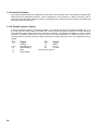
4.2.4 Printhead Drivers
During DP6 printing, a pulse at NAND gate U27 pin 3 simultaneously loads 74LS273 latch U6 with 8 bits
indicating which printwires are to be driven and triggers print pulse timer U14. Each high bit in U6 applies +30
VDC to one side of the corresponding printwire coil via NPN predrivers U5 and TIP126 or TIP127 PNP drivers
Q4 to Q12. Timer U14 applies -30 VDC to the other side of all printwire coils via Q17 and power MOSFET Q3.
(During DP7 printing, 24 bits of print dot data are serially shifted into U5 to U7. A pulse at OR gate U14 pin 6
then transfers the 24 bits to the U5 to U7 outputs. Each high bit turns on a printwire by activating power
MOSFETS Q5 to 28. Timer U17 applies +30VDC to the other side of all printwire coils via Q1 and power
MOSFET Q3.)
The pulse length of timer U14 (U17) is inversely proportional to the actual +30 VDC voltage level. As +30 VDC
rises the current level in the coils increases more rapidly so the timer pulse shortens to keep the peak coil
current relatively constant. When the timer pulse ends, it turns off Q3 and current in the coils circulates back
to the +30 VDC supply through D7 (D32). The timer turn off also enables print pulse oscillator U15 (U18)
which toggles Q3 on and off as an open-loop switching regulator to keep the current circulating in the coils
relatively constant. Finally, 6522 timer output U20 (U23) pin 17 goes high which clears the printwire bits from
U6 (U5 to U7) and resets both U14 & 15 (U17 &18). This turns off all transistors and the current in the coils
rapidly discharges through diodes D8 to 16 (D6 to 29). (In the DP7 timer U16 enables this discharge path
through Q4 for about 40 usec. after the 6522 timer output goes high. Then U16 turns off Q4 and the
remaining coil current is dissipated in Q5 to 28.) See Figure 4-2 for typical waveforms.
29
+30v
DATA N
F
A
____
FIRE
18
10
11
Q4 – Q12 TYP.
74LS273
U6
ULN2003
-30v
G
D8 – D16 TYP.
______
PINSTB
B
Timer
U14
C
H
+30v
3
D7
D
Timer
U15
3
E
6
U17
5
Q3
4
-30v
0
100s
200s
300s
5v
U18 - 10
A
0v
U14 - 2
B
5v
0v
5v
U14 - 3
0v
C
5v
U15 - 3
D
0v
U17 - 4
E
5v
0v
U15 - 5
0v
F
+30v
Q9 COL
(TAB)
G
Q3 DRAIN
(TAB)
H
0v
-30v
+30v
0v
-30v
30
FIG 4.2 PRINTHEAD DRIVE CIRCUIT
4.2.5 Keypad and Display (Refer to Schematics #72082 and #72080 or #72115)
The keypad switches are arranged in a 4 by 4 X-Y grid. Address lines A0 to A3 drive the grid rows through
74LS367 buffer U10 (U12 in the DP7) and the grid columns are read onto the 6809 data bus through
74LS245 transceiver U19 (U22).
The display is a 2 line by 16 character liquid crystal display (LCD) with integral electronics. All data transfers
between the 6809 and the display are buffered through transceiver U19 (U22). When the 6809 is ready to
display data, it reads status from the LCD and if the LCD is ready to accept data, the 6809 writes ASCII
characters to the LCD. The LCD then generates and displays the corresponding character patterns.
4.2.6 Sensors
Four optical sensors are used: the left home sensor for carriage position, the front and rear document sensors
for document presence and position and the sensor on the keypad PCB for cover open condition. All sensors
operate in the same way: a constant current is provided to the integral light emitting diode (LED) of the sensor
through a resistor to +5 volts. The LED light turns on the corresponding phototransistor, raising its emitter
voltage to about 3.5 VDC. When an object is placed in the slot between the LED and the phototransistor, the
transistor turns off and its emitter is pulled down to ground by a resistor. Sensor status is read by the 6809 via
74LS365 buffer U7 (U8 in the DP7). Printers with the auto alignment feature add a fifth sensor for detecting
skew of the inserted document. Both this sensor and the rear document sensor are reflective sensors which
turn on their phototransistors when a document is present.
4.2.7 Character Printing
The carriage motor steps the carriage in 1/120" increments but dots can be printed twice per increment (3
times per increment in the DP7). Printing at 10 characters per inch (cpi) uses a 9 wide by 8 high (13 X 22)
character matrix. Nine (13) increments are used for printing a character and 3 (5) increments for the
intercharacter space. Printing at 12 cpi uses a 7 X 8 (11 X 22) matrix with 7 (11) increments used for printing
and 3 (4) for spacing. Printing at 17.1 cpi uses a 9 X 8 (7 X 22) matrix with 9 half (7) increments used for
printing and 5 (3.5) for spacing. At correspondence quality (CQ) speed half increment printing is used to
double the horizontal resolution and the matrix doubles to 17 X 17 (25 X 22) for 10 cpi and 13 X 17 (19 X 22)
for 12 cpi. DP6 CQ is printed in two passes with the document moved by 1/2 dot between passes to double
the vertical resolution. DP7 CQ is printed in a single pass.
At all print speeds only every other dot position can be printed so the maximum number of horizontal dots
printed is 4 for a 7 wide matrix, 5 for a 9 wide, 6 for an 11 wide, 7 for a 13 wide, 9 for a 17 wide, 10 for a 19
wide and 13 for a 25 wide matrix. In all print modes the upper 7 (17) printwires are used for printing normal
characters, the eighth (18th through 22nd) wire for lower case descenders and the ninth (23rd & 24th) wire for
underlining.
Printwire impact force and print density decrease as the printwire cycling frequency increases. Draft and CQ
print at a maximum frequency of 1,000Hz (1,350Hz) and normal print occurs at a maximum frequency of
750Hz (1,350Hz).
31
5.0
MAINTENANCE
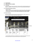
5.1 LUBRICATION AND CLEANING
5.1.1 Lubrication
There are no lubrication points in the printer. All parts are either permanently lubricated or are designed to
operate dry. No lubricants should be used. They may adversely affect operation.
5.1.2 Document Feed Roller Cleaning
1. Remove the cabinet lid.
2. Moisten a lint-free cloth with isopropyl alcohol and wipe the front rollers while rotating the gear on the end of
the roller shaft. Do not use any strong solvents in place of alcohol.
3. In similar fashion, clean the rear rollers. Make sure all rollers are dry and free of residue.
5.1.3 Document Sensor Cleaning
Clear document sensor light paths of paper dust and other obstructions if rollers continue to run
when no document is present.
1. Insert the flexible nozzle tube of a compressed air can under the input guide and near each of
the document sensors (2 sensors on printers without auto alignment, 3 sensors on auto
alignment printers). Clear each sensor area with a 5 second burst of air.
DP6 & DP7 without Automatic Alignment
Upper
Roller
Document Sensors
Sensor Holes
Input Guide
Back sensor
Skew sensor
DP7 with Automatic Alignment
Document
Sensor
Sensor Hole
Input Guide
5.1.4 Printhead Cleaning
Perform when printwires stick or print quality becomes intermittent. Be sure to check the ribbon
first! All necessary tools are included in the 73297-1 Printer Cleaning Kit.
32
5.1.4.1 DP6 Printhead Cleaning
1. Remove the cabinet lid and ribbon cartridge.
2. Remove the 2 screws fastening the printhead to the carriage.
3. Disconnect the printhead from the printhead flex cable.
4. Clean the tip of the printhead nose where the printwires extend from the printhead with an alcohol
wetted napkin. Remove all ink and bits of ribbon fabric lint.
5. Use the blunt end of a printhead cleaning brush to remove the bulk of the grease packed around the
printwires. Then wet the brush end with alcohol to do remove the rest of the grease from the printwires.
Wipe the grease, ink and ribbon fabric “lint” from the brush onto the napkin provided.
6. Use the syringe filled with printhead lubricant to replace the “grease pack”.
7. Replace the printhead and reconnect it to the flex cable. (The white spacer between the printhead and
the carriage is critical to correct operation.)
8. Tighten the mounting screws while pushing the printhead down so the plastic nose flange sits flush
against the edge of the carriage slot. Check the printhead gap.
9. Reinstall the ribbon shield and ribbon cartridge. Perform a test print.
Release Bar
DP6 CARRIAGE
Ribbon Drive Knob
Printhead Fins
Printhead Attach Screws (2) (white
plastic spacer is behind printhead)
Printhead Nose
Leftmost Roller
Gap Adjust Screws (2)
Carriage Shaft
Ribbon Shield
DP6 Printhead
(Rear View)
Printwires
Grease Pack
Jewel
Printwires
Tip of Printhead Nose
33
5.1.4.2 DP7 Printhead Cleaning
1. Remove the cabinet lid and ribbon cartridge.
2. Remove the ribbon shield by raising the carriage, pushing down on the shield until it snaps free from the
carriage and sliding it out to the right.
3. Remove the screw fastening the printhead to the carriage.
4. Disconnect the printhead from the 2 printhead flex cables.
5. Remove the printhead by tilting it forward while lifting the carriage.
6. Clean the tip of the printhead nose where the printwires extend from the printhead with an
alcohol wetted napkin. Remove all ink and bits of ribbon fabric lint.
7. Replace the printhead and reconnect it to the flex cables.
8. Tighten the mounting screw.
9. Replace the ribbon shield and cartridge and do a test print.
On the DP7 printer, remove this
screw to remove printhead.
Removing this screw on the
DP6 will irreparably damage
the printhead.
DP7 Printhead Nose Tip
Jewel
Printwires
5.1.5 Document Print Area Cleaning
Accumulated paper dust should be brushed or vacuumed occasionally from the platen, printhead, carriage
shaft, feed rollers, document sensor and other the document path areas.
5.1.6 Cabinet Exterior Cleaning
The cabinet can be cleaned with a damp cloth and a mild, liquid soap or detergent. Do not use harsh,
abrasive cleaners.
34
5.2 SERVICE PARAMETER SET-UP PROCEDURE
It may be necessary to reset service parameters that compensate for certain mechanical tolerances. These
parameters are listed on a label inside the printer and may be reentered if necessary by the 94 FUNCT(see
3.6.3). If mechanical parts are replaced some parameters may have to be reset. New parameter values
should be marked on the configuration label.
The service parameters are described in 3.6.3 and are determined by using 95 FUNCT local printing and 944
FUNCT forward/reverse printing as described below. Parameter values are changed with the A and B keys.
After changing a parameter, use 95 and 944 FUNCT to obtain new print samples. Measure all distances
again and re-adjust if necessary.
TOP OFFSET is set so the distance from the top document edge to the center of the first line printed by 95
FUNCT is located as specified by LINE #1 = .XXX under 92 FUNCT.
INDEX OFFSET sets the distance that a document moves after it is semi-automatically inserted. To adjust
this parameter, configure 92 FUNCT for BEGIN PRINTING AFTER ENTER KEY. Insert a document and then
move it slightly into the printer with the A key. Draw a line across the document directly beneath the front
edge of the metal input guide above the document. Press ENTER and the document will be repositioned. Set
the INDEX OFFSET so that the first line printed by 95 FUNCT is centered on the line drawn across the
document.
LEFT OFFSET is set so the carriage can still move leftward from its position after document insertion 0.01" to
0.02" (0.3 to 0.5mm) before it is stopped by mechanical interference.
LEFT MARGIN is set so the distance from the left document edge to the left edge of the first character printed
by 95 FUNCT is 0.20" (5.1mm)
CAR ALIGN is set so that the center of 80 character lines printed from right to left align with those printed left
to right by 95 FUNCT.
944 FUNCT prints a line of X's advances the document 10", prints another line of X's, reverses the document
10", prints a line of O's, advances the document 10", prints another line of O's and then ejects the document.
It is used to set the following three parameters.
FORWARD COMPENSATION is set so that the distance between lines of X's printed by 944 FUNCT is
10.00" (254mm) +/- 0.02” (0.5mm)
REVERSE COMPENSATION is set so that the line of O's printed at the top of the page overlaps the line of
X's within 0.02” (0.5mm).
EJECT HOLD OFFSET is set so that when a document printed by 944 FUNCT is ejected it is still held in the
front drive rollers but can be removed by pulling gently on the document.
CONFIGURATION selects certain custom operating features and should not be set to a value other than
shown on the configuration label without contacting the factory.
NORMAL DARKNESS (DP7 only) Lower values reduce darkness and increase ribbon life at normal print
speed. Select the lowest value that provides suitable legibility on thick forms. CQ DARKNESS similarly
controls darkness at correspondence quality print speed.
5.3 ELECTRICAL ADJUSTMENTS
There are no electrical adjustments required. Do not adjust the preset potentiometer on the main PCB
without consulting the factory.
35
5.4 MECHANICAL ADJUSTMENTS
5.4.1 DP6 Printhead Gap
Too large a gap causes light print and missing dots. Too small a gap causes ribbon smear.
1. Remove the cabinet lid and ribbon cartridge (See 5.5.1).
2. Turn off power.
3. Flex the plastic ribbon shield and remove it from its holder.
4. Insert a .017" (.42 mm) feeler gauge between the platen (printing surface) and printhead nose from the side
of the printhead. Insure that the feeler is flat against the platen and not beneath the plastic carriage slider.
The .017" feeler should just fit without raising the printhead but a slight resistance should be felt as the
feeler slides below the printwires.
5. If the gap is incorrect, slightly loosen the two larger head screws on either side of the printhead (Not the
screws fastening the printhead to the carriage!) that fasten the gap plate to the carriage bracket. The gap
changes as these screws are loosened so only loosen them enough to be able to move the plate. (See
drawing in 5.1.4.1 above.)
6. Push the gap plate down so the gap is more than .017" and then push the printhead down so that the
printwires just contact the .017" feeler. Insure that the gap plate is centered around the printhead nose and
tighten the screws. Recheck the gap per step 4.
7. Replace the ribbon shield. Insure the shield tabs are set firmly and securely in the holder and the shield slot
is toward the printer rear.
8. Mount the ribbon and use 95 FUNCT to print locally (See 3.9) to check print quality.
36
5.4.2 DP7 Printhead Gap
Too large a gap causes light print and missing dots. Too small a gap causes ribbon smear.
1. Remove the cabinet lid and ribbon cartridge (See 5.5.1).
2. Turn off power.
3. Remove the ribbon shield by raising the carriage, pushing down on the shield until it snaps free from the
carriage and sliding it out to the right.
4. Insert a .013" (.32 mm) feeler gauge between the platen (printing surface) and printhead nose from the side
of the printhead and behind the slider (plastic pivoting piece in front of the printhead nose). Insure that the
feeler is flat against the platen. The .013" feeler should just fit without raising the printhead but a slight
resistance should be felt as the feeler slides below the printwires.
5. If the gap is too small, it may be due to slider wear. Replace the slider with a new one if available. Remove
the old slider by pushing it down while holding up the carriage. See drawing in paragraph 5.6.8 below.
Orient the new slider below the slider pivot pin so that the notched corners face toward the printer rear.
Push the carriage down against the slider until it snaps onto the slider pivot pin. Check that the slider pivots
freely. Check the gap with the .013” feeler. If the gap is incorrect, proceed as follows:
6. On units with serial numbers below 70091 the gap must be adjusted by repositioning the gap plate as
described for the DP6 in 5.4.1 steps 5 & 6 but with a .013” gap. Then skip to step 12 below.
On all later units, proceed as follows:
8. Loosen the rear screws fastening the platen to the document drive side plates. Do not loosen the front
platen screws that also locate the document drive roller spring cams. See drawing below.
9. Increase the gap by pushing the rear platen screwheads downwards. Decrease the gap by
raising the rear platen screwheads.
10. Check the gap with the .013’” feeler. When it is correct, tighten the platen screws.
Rear platen screw (2)
Roller spring
Roller spring cam
Left side of document drive (with cabinet removed)
11. Replace the
ribbon
shield by raising the carriage, sliding the shield between the carriage and the printhead until the shield slot
is centered and then gently push the carriage down until the shield snaps into place
12. Mount the ribbon and print locally (see 3.9) to check print quality. Adjust the NORMAL and CQ DARKNESS
parameters (see 5.2).
37
5.4.3 Carriage Drive Belt Tension
The carriage belt connects the carriage drive motor mounted in the right end of the box with the carriage. Low
carriage belt tension can cause uneven character size and spacing or carriage stalling.
1. With the carriage in its leftmost position, use a spring gauge to deflect the center of the carriage belt.
Proceed to step 2 only if the force to deflect one side of the belt so that it just touches the other side of the
belt is not between 15 and 17 ounces (425-475 gms).
2. Remove the cabinet (see 5.5.1).
3. Locate the screw fastening the carriage idler pulley arm at the left end of the carriage drive belt to the left
pivot arm. Turn it to clockwise to increase or counter clockwise to decrease the belt tension. Repeat step
1.
5.4.4 Document Drive Belt Tension
The document drive belt connects the document drive motor mounted to the left side of the box with the rear
document drive roller. Low document belt tension causes uneven line spacing and document drive stalling.
1. Remove the cabinet (see 5.5.1).
2. Use a spring gauge to deflect the center of the document drive belt. Proceed to step 3 only if the force
measured to deflect the belt 1/16" (1.5mm) is not between 1.5 and 2.5 ounces (40 and 70 gms).
3. Loosen the 3 screws that fasten the document drive motor to the metal box. Do not loosen too much or the
jam nuts inside the box will fall off the screws.
4. Move the motor toward or away from the rear document drive roller to adjust the tension and tighten the
screws. Repeat step 2.
5.4.5 Carriage Left Home Position
1. Only use the following procedure if the LEFT OFFSET parameter is not displayed by 94 FUNCT. If it is, use
it to set left home (see 5.2).
2. Turn on power and insert a document to activate the carriage motor.
3. Loosen the set screw that fastens the drive pulley to the motor.
4. Push the carriage as far to the left as possible, then move it to the right about .020" (0.5 mm) and tighten
the set screw.
5. Check that the carriage tab slides into the left home sensor without binding. Bend the tab if necessary.
5.4.6 Wheel Guide
The wheel guide holds the carriage guide wheel against the box. A loose wheel guide can cause wavy
printing. A tight wheel guide can cause carriage stalling.
1. Remove the cabinet (see 5.5.1).
2. Loosen the screws on each end of the metal box fastening the wheel guide arms to the box.
3. With the carriage in its leftmost position, insert a .010" (.25 mm) feeler gauge between the guide wheel and
the box. Push the wheel guide against the guide wheel and insure that the wheel guide arms are
horizontal. Tighten the 2 wheel guide screws.
4. Move the carriage to its rightmost position and repeat step 3.
5. Adjust the envelope ramp on DP6’s below S/N 00588 (see 5.4.6).
38
5.4.7 Envelope Ramp (DP6 below S/N 00588)
1. Move the carriage toward the right so that the printhead nose is still above the black platen but the flat top
surface of the white plastic ramp is beneath the carriage flange.
2. Loosen the ramp screw on the wheel guide and adjust the ramp height so that the ramp raises the carriage
0 to .010" (.25 mm) off the platen. Insure that the upper surface of the ramp is parallel to the carriage
flange and that it doesn't move when the screw is tightened.
5.4.8 Document Input Tray Height
1. Remove the cabinet (see 5.5.1).
2. Raise the input tray to its non-operating position.
3. Slightly loosen the 2 screws that fasten the tray support to the side plates and raise the tray support as far
as possible.
4. Lower the input tray until it is horizontal (the height of the input tray near the tray support is within .03"
(0.8mm) of the height of the tray at its front edge) and tighten the screws so that the tray support holds the
input tray horizontal.
5.4.9 Document Drive Roller Spring Force
The document drive roller springs are formed wires that pull both front and rear upper document drive rollers
against the lower rollers. The springs are mounted to both document drive side plates and adjusted by raising
or lowering the cams mounted on the front screws fastening the side plates to the platen. Incorrect spring
force can cause document skewing, slipping or stalling
1. Remove the cabinet (see 5.5.1).
2. Use a spring gauge to measure the force required to raise the right end of the front pinch roller very slightly.
It should measure 3 to 4 ounces (85 to 115 gms).
3. If necessary, adjust this force by loosening the roller spring cam screw on the right side plate and raising or
lowering the cam.
4. Repeat steps 2 & 3 on the left end of the front pinch roller but adjust to 12 to 13 ounces (340 to 370 gms).
5.4.10 Document Edge Guide Squareness
1. Insert a known good square against the front drive rollers so that it contacts the rollers evenly. Slide the
square leftward until it contacts the edge guide. The guide and the perpendicular edge of the square must
be parallel.
2. If adjustment is necessary, remove the guide cover from the edge guide by prying it upward.
3. Loosen the 3 nuts fastening the edge guide to the input tray.
4. Insure that the square is evenly contacting the rollers and that its left edge is flush against the document
sensor PCB.
5. Position the edge guide with its right edge flush to the square and its rear edge flush to the sensor PCB. At
the same time position the clear top guide so that its right rear corner fits flush into the mating edges of the
stainless steel guide above the rollers. Tighten the 3 nuts.
6. Reattach the decorative cover using new pieces of 1/8" thick foam adhesive tape.
39
5.4.11 Print Skew
Perform this adjustment if the printing is not perpendicular to the left document edge.
1. With power on, insert an 8 1/2" wide document with known good perpendicular edges into the rear
document drive rollers and insure that its left edge is still flush to the edge guide.
2. Print an 80 character line of local printing (see 3.9) and eject.
3. The distance from the top document edge to the bottom of the print line should be the same within .01" (.25
mm) on both ends of the print line. Proceed only if adjustment is necessary.
4. Remove the cabinet (see 5.5.1)
5. Loosen the 2 screws that fasten the right document drive side plate to the right side of the metal box.
6. Move the right side of the document drive further into the box to rotate the print line clockwise. Move it out
of the box to rotate the print line counterclockwise. Do not move it so far that the carriage binds against the
upper exit guide or the ribbon shield support binds against the upper input guide.
7. Tighten the screws and return to step 2.
8. If skew cannot be eliminated by moving the right end of the document drive, move the left end but and then
check the document drive belt tension and top offset (see 5.2 & 5.4.3)
5.4.12 Auto Alignment Gate Ramp
1. Insert an Allen wrench through the hole in the tray support and loosen the ramp adjustment screw.
2. Hold the ramp arm against the right side plate and move the ramp adjustment screw toward the right until
the gate just begins to rise. Tighten the screw in this position
Ramp Arm Assy
Ramp adjustment screw
Ramp
Gate bushing
Move ramp this way to
lower gate
Move ramp this way to
remove play
View: Gate arm from front of printer with tray support removed
Roller Spring Mounting Screw
Gate Actuation Arm
View: Right side of DP7 w/automatic alignment with cabinet removed.
5.4.13 Auto Alignment Roller Spring Tension
1. Raise the gate by pressing 9 4 7 FUNCT A.
2. Manually feed an ½” wide strip of the thinnest paper used on the machine (usually a receipt copy under the
rightmost front upper roller segment.
3. Pull the paper out from under the roller segment. Adjust the roller spring tensioning screw on the right side
plate so ther is a very light drag from the roller on the paper. Clockwise adjustment increases drag.
40
4. Repeat steps 2 and 3 for the leftmost roller segment and the roller spring tensioning screw on the left side
plate.
5.4.14 Auto Alignment Gate Travel
Roller Segments
Roller Shaft
Input Guide
Gate fingers
1. Raise the
gate by pressing 9 4 7 FUNCT A.
2. Press FUNCT to adjust the gate height. The gate fingers should be as close as possible (within 0.02” or
0.5mm) to the input guide without touching it. Each press of A will slightly raise the gate and each press
of B will slightly lower the gate. When the gate is at the correct height, press ENTER.
3. Press B to lower the gate to its deactivated position and then pressA to check for correct activated gate
height. Press CLEAR to exit the test. Recheck by repeating step 1.
5.4.15 Auto Alignment Skew Sensor Calibration
1. Press 9 4 6 FUNCT to display “Skew Calibration”.
2. Insert a document with known square top and left edges. If the document inserts straight and its top edge is
perfectly parallel to the input guide edge, press ENTER to calibrate the skew sensors and exit. If the
document did not insert perfectly, press EJECT and insert again.
5.4.16 DP7 Carriage Spring
The spring between the box and the right pivot arm reduces the carriage force against the platen, minimizing
picking of document edges and slider wear. To adjust spring tension rotate the spring hooks. Tension should
be set as high as possible without causing lighter print near the edges of thick documents.
41
5.4.17 DP7 Carriage Lift Button
The carriage lift button raises the carriage at its right home position so that envelopes and other wide
documents may be fed without the carriage weight pressing on them.
1. Remove the ribbon shield by raising the carriage, pushing down on the shield until it snaps free from the
carriage and sliding it out to the right.
2. Move the carriage to the position on the right side of the printer where the carriage is lifted to its highest
point by the lift button.
3. The gap between the printwires and the platen should now be between 0.026” and 0.030”.
4. To adjust, slightly loosen the right front wheel guide clamp screw and raise or lower the wheel guide to get
the proper print gap. Tighten the screw while holding the wheel guide.
5. Reheck the gap and repeat step 4 if necessary.
Carriage lift
cam 67296
Carriage lift
button 67334
42
Wheel guide locking
screws
5.5 REPLACEMENT PROCEDURES
5.5.1 Cabinet
1. Turn off power and remove the cabinet lid.
2. Loosen 4 screws located in each corner of the cabinet.
3. Raise the input tray and then lift off the cabinet.
5.5.2 Main PCB
1. Record all FUNCT 92 and 93 parameters so the new PCB can be configured correctly. If replacing a DP7
PCB, installing serial EEPROM U11 from the old PCB in the new PCB will transfer all parameters.
2. Remove the cabinet (see 5.5.1).
3. Remove the 2 screws in the PCB upper corners or, if the PCB has button fasteners, pry each upper corner
free and fold the PCB down.
4. Disconnect the following cables (see Assy Dwg #72080 for DP6 or #72115 for DP7):
DP6
DP7
Description
J1
J1
input power
J2
J2
carriage stepper motor
J3
J3
document stepper motor
J4
J4&5
printhead
J5
J6
carriage home & document sensors
J6
J7
interface
J7
J8
keypad/display
5. Raise the PCB and remove the hinge screw in each lower corner.
6. To replace the PCB, reverse the procedure in steps 3 to 5.
7. Reconfigure the new PCB with the FUNCT 92 and 93 parameters recorded in step 1 and the FUNCT 94
parameters listed on the configuration label.
5.5.3 Battery
1. Record all 92 and 93 FUNCT parameters.
2. Turn off power and remove the cabinet (see 5.5.1).
3. Remove the 2 screws in the PCB upper corners or, if the PCB has button fasteners, pry each upper corner
free and fold the PCB down.
4. Remove the old battery from its holder and discard it in a way that won't expose it to flame or high
temperature.
5. Install a new #68026 Lithium battery in the holder with the "+" terminal facing away from the PCB. Replace
only with the same or equivalent type.
CAUTION: Danger of Explosion if battery is incorrectly replaced !
6. Remount the PCB and cabinet.
7. When the printer is powered on, POWER FAILURE will be displayed. Press FUNCT and reenter the 92 and
93 FUNCT parameters recorded in step 1 and the FUNCT 94 parameters listed on the configuration label.
5.5.4 Keypad/Display Assembly
1. Remove the cabinet (see 5.5.1).
2. Remove the 2 screws in the PCB upper corners or, if the PCB has button fasteners, pry each upper corner
free and fold the PCB down.
3. Disconnect the Keypad/Display cable from J7 of the Main PCB.
4. Remove the 5 screws fastening the metal box top to the box.
5. Remove the 4 screws fastening the keypad/display to the box top and remove the keypad/display.
6. To install a new keypad/display reverse the procedure in steps 1 to 5
5.5.5 AC board
1. Turn off power and unplug the AC Cord.
2. Facing the rear of the printer remove the screw on the right end of the AC cord receptacle and the screw to
the left of the power switch.
3. Slide out the AC PCB and disconnect the transformer connector.
4. To install a new AC PCB reverse the procedure in steps 1 to 3.
43
5.5.6 Carriage Home Sensor
1. Remove the cabinet (see 5.5.1).
2. Remove the 2 screws in the PCB upper corners or, if the PCB has button fasteners, pry each upper corner
free and fold the PCB down.
3. Disconnect the Carriage Home Sensor cable from J5 of the Main PCB.
4. Remove the 2 screws fastening the sensor to the left pivot arm and remove the cable tie fastening the
sensor cable to the pivot arm.
5. To install the new sensor reverse the procedure in steps 1 to 4.
5.5.7 Document Sensor
This does not apply to document sensors in printers with the automatic alignment feature. See 5.5.14 and
5.5.15 for replacement of those sensors.
1. Remove the cabinet (see 5.5.1).
2. Remove the 4 screws mounting the mechanism to the baseplate.
3. Remove the 2 screws in the PCB upper corners or, if the PCB has button fasteners, pry each upper corner
free and fold the PCB down.
4. Disconnect the Document Sensor cable from J5 of the Main PCB.
5. Slide the left roller spring off the roller spring cam and lift the spring off the front roller.
6. Remove the screws fastening the input guide and the document sensor to the left side plate. Keep the
sensor mounting spacer that is freed when the sensor mounting screw is removed.
7. Raise the input tray and slide the sensor to the left to free it from the input guide. Lift the left ends of the
front roller and the input guide just enough to remove the sensor.
8. Mount the new sensor and route its cable back under the document drive to the Main PCB.
9. Push the mechanism toward the front right corner of the baseplate before fastening them.
10. Insure that the sensor PCB sits flush against the baseplate and left edge of the input guide and that the
sensor cable passes under the sensor mounting spacer.
11. Reverse the procedure in steps 1 to 6. Insure that the left roller spring is inside the roller bushing flanges
and that the spring ends hook inside the side plate slots.
12. Adjust the input guide so there is no more than .020” clearance between it and the carriage.
13. Adjust the TOP, INDEX and EJECT HOLD offsets under so that inserted documents are correctly
positioned (See 5.2). Record any new values on the parameter label.
44
5.5.8 Transformer
1. Turn off power and unplug the AC Cord.
2. Remove the cabinet (see 5.5.1) and the AC PCB (see 5.5.5).
3. Remove the 2 screws in the PCB upper corners or, if the PCB has button fasteners, pry each upper corner
free and fold the PCB down.
4. Disconnect the input power connector from J1 of the main PCB.
5. Remove the screw to the left of the transformer that fastens the chassis grounding wires to the metal box.
6. Remove the 2 screws that fasten the transformer to the metal box.
7. See 2.3 to insure that the new transformer is wired for the correct input voltage. CONNECTION OF A
TRANSFORMER WIRED FOR 115 VAC TO A 230 VAC INPUT CAN CAUSE PERMANENT DAMAGE
TO THE PRINTER!
8. To install a new transformer reverse the procedure in steps 1 to 6. Route the transformer wires under the
carriage motor so the main PCB input power connector does not pull off.
5.5.9.1 DP6 Printhead
1. Remove the cabinet lid and ribbon cartridge.
2. Remove the 2 screws fastening the printhead to the carriage. See drawing in 5.1.4.1.
3. Disconnect the printhead from the printhead flex cable.
4. Mount the printhead spacer and mounting screws on the new printhead.
5. Replace the printhead and reconnect it to the flex cable.
6. Tighten the mounting screws while pushing the printhead down so the plastic nose flange sits flush against
the edge of the carriage slot.
7. If possible, check the printhead gap (see 5.4.1).
8. Check the top offset parameter (see 5.2)
5.5.9.2 DP7 Printhead
1. Remove the cabinet lid and ribbon cartridge.
2. Remove the ribbon shield by raising the carriage, pushing down on the shield until it snaps free from the
carriage and sliding it out to the right.
3. Remove the screw fastening the printhead to the carriage. See drawing in 5.1.4.2
4. Disconnect the printhead from the 2 printhead flex cables.
5. Remove the old printhead by tilting it forward while lifting the carriage.
6. Replace the printhead and reconnect it to the flex cables.
7. Tighten the mounting screw.
8. If possible, check the printhead gap (see 5.4.2).
9. Replace the ribbon shield and cartridge. Adjust TOP OFFSET, NORMAL and CQ DARKNESS (see 5.2).
5.5.10 Carriage Drive Belt
1. Remove the cabinet (see 5.5.1).
2. Remove the screws fastening the belt clamp.
3. Remove the screw fastening the carriage idler pulley arm to the left pivot arm. The belt and pulley arm are
replaced as an assembly.
4. To install the new belt reverse the procedure in steps 2 and 3.
5. Tension the carriage belt (see 5.4.2).
6. Set the LEFT HOME (see 5.4.4), LEFT MARGIN and CAR ALIGN parameters (see 5.2).
45
5.5.11 Carriage Motor
1. Remove the cabinet (see 5.5.1).
2. Remove the 2 screws in the PCB upper corners or, if the PCB has button fasteners, pry each upper corner
free and fold the PCB down.
3. Disconnect the carriage motor cable from J2 of the Main PCB.
4. Remove the 4 screws fastening the carriage motor to the metal box.
5. Transfer the carriage motor pulley to the new motor. Leave a .01" (0.2mm) gap between the pulley hub and
the motor flange.
6. Assemble the 4 screws to the new motor. The DP6 uses a second flat washer on the upper screw closest
to the transformer. The DP7 uses shorter screws on the side closer to the transformer. Carefully install the
motor in the box and fasten but do not tighten the screws.
7. Insure that the transformer cables are not pinched by the motor. With the carriage near the right side of the
printer, locate the motor vertically so that the carriage drive belt is horizontal from the motor pulley to the
carriage clamp surface and tighten the motor mounting screws.
8. Tension the carriage belt (see 5.4.2).
9. Set the LEFT HOME (see 5.4.4), LEFT MARGIN and CAR ALIGN parameters (see 5.2).
10. Reverse the procedure in steps 1 to 3.
5.5.12 Document Drive Belt
1. Remove the cabinet (see 5.5.1).
2. Slide the belt between the 2 drive rollers off the rear roller pulley
3. Slide the document drive belt off the document motor pulley.
4. Install the new document drive belt and the old connecting belt.
5. Tension the drive belt (see 5.4.3).
5.5.13 Document Motor
1. Remove the cabinet (see 5.5.1).
2. Remove the 2 screws in the PCB upper corners or, if the PCB has button fasteners, pry each upper corner
free and fold the PCB down.
3. Disconnect the Keypad/Display cable from J7 of the Main PCB.
4. Remove the 5 screws fastening the metal box top to the box and remove the box top.
5. Disconnect the document motor cable from J3 of the Main PCB.
6. Remove the 3 screws fastening the document motor to the metal box.
7. Transfer the document motor pulley to the new motor. Leave a .02" (0.5mm) gap between the pulley hub
and the motor flange.
8. Install the new motor by reversing the procedure in steps 2 to 6.
9. Slide the document drive belt onto the motor pulley and tension the belt (see 5.4.3).
5.5.14 Auto Alignment Skew Sensor
1. Remove the two nuts fastening the skew sensor to the input guide.
2. Disconnect the skew sensor from the input sensor by pulling it upward
3. Install the lower sensor insulator, the new skew sensor and the upper sensor insulator.
4. Adjust the TOP, INDEX and EJECT HOLD so that inserted documents are correctly positioned (See 5.2).
Record any new values on the parameter label.
5. Calibrate the skew sensor (See 5.4.14).
46
5.5.15 Auto Alignment Input Sensor
1. Remove the cabinet (see 5.5.1).
2. Remove the 4 screws mounting the mechanism to the baseplate.
3. Remove the 2 screws in the PCB upper corners or, if the PCB has button fasteners, pry each
upper corner free and fold the PCB down.
4. Disconnect the Input Sensor cable from J5 of the Main PCB.
5. Remove the Auto Alignment Skew Sensor (see 5.5.14)
6. Remove the input tray support.
7. Remove the screw fastening the input sensor to the left side plate. Keep the sensor mounting spacer that is
freed when the sensor mounting screw is removed.
8. Mount the new sensor and route its cable back under the document drive to the Main PCB. Assure the
cable does not run under the gate or gate assembly hardware.
9. Push the mechanism toward the front right corner of the baseplate before fastening them.
10. Insure that the sensor PCB sits flush against the baseplate and left edge of the input guide and that the
sensor cable passes under the sensor mounting spacer.
11. Reverse the procedure in steps 1 to 6.
12. Adjust the input tray height (See 5.4.7).
13. Adjust the TOP, INDEX and EJECT HOLD offsets so that inserted documents are correctly positioned
(See 5.2). Record any new values on the parameter label.
14. Calibrate the skew sensor (See 5.4.14).
5.5.16 Ribbon Drive Cable
1. Before proceeding, read the rest of this procedure to insure that the correct routing of the new cable is
understood. Refer to assy. drawing 73255-1 for DP6 or 73255-4 for DP7.
2. Remove the cabinet (see 5.5.1). Move the carriage to the center. If working with a DP7, remove the home
sensor from the left pivot arm. If working with a DP7 or if there are 2 ribbon cable springs on the DP6 left
pivot arm, remove the old cable and upper spring and skip to Step 7.
3. Remove the screw from the middle of the right pivot arm slot. Slide the cable ball ends to the middle of the
slot to release them from the arm and remove the cable. Discard the screw and cable.
4. Remove the cotter pin mounting the ribbon cable yoke and spring to the middle of the left pivot arm slot.
Discard the pin, yoke and spring.
5. Insert the long cotter pin (supplied) through the lower hole in the left pivot arm slot until the pin loop
contacts the arm hole and then bend the pin legs flush against the arm and around the edges of the arm.
Similarly mount the short cotter pin to the pivot arm slot upper hole..
6. Attach one of the springs (supplied) to the lower cotter pin loop.
7. Kinking the new cable during installation can shorten its life. Keep a slight tension on the cable while routing
so it will not unwind.
8. Attach one cable end to the lower spring mounted on the pivot arm.
9. Route the cable under the rear ribbon drive pulley and then over the top of the rear pulley.
10. Route the cable end back under the rear pulley so that it passes (DP6:behind, DP7:in front of) the previous
wrap.
11. Route the cable through the bottom pivot arm hole, through the channel of the plastic ribbon cable retainer
(supplied) and back through the top pivot arm hole.
12. Thread the cable end over the top of the front drive pulley.
13. Route the cable around the front pulley and again thread it over the top of the front pulley so it passes
(DP6:behind, DP7: in front of) the previous wrap.
14. Attach the cable end to the other spring and stretch the spring just enough to attach it to the upper spring
fastening loop.
15. Move the carriage back and forth. Check for smooth travel of the cable around the two pulleys and for
equal tension on both springs.
16. Reinstall the DP7 left home sensor.
47
5.6 TROUBLESHOOTING
5.6.1 Basic Troubleshooting Procedure
This procedure exercises everything in the printer except the interface to the host system. If any step is not
successfully executed, refer to the corresponding troubleshooting section.
1. Turn on printer power.
A) If nothing appears on the display, see 5.6.2.
B) If < > BAD is displayed, replace the indicated component on the main PCB or the
complete main PCB.
C) If CARRIAGE FAULT is displayed, see 5.6.6.
2. Press 12345678 and then CLEAR. Each number should appear in the display and then all should
disappear. If this does not occur or if diagnostics don't begin to execute in the next step, see 5.6.3.
3. Execute 90 FUNCT diagnostics (see 3.7) and exercise the three sensors. If any sensor does not operate,
see 5.6.4.
4. Execute Local Printing (see 3.9) and use an 8 1/2" x 11" document.
A) If a document will not load into the printer, see 5.6.5.
B) If the carriage will not move across the document, see 5.6.6.
C) If no printing occurs, see 5.6.7.
D) If print quality is not acceptable, see 5.6.8.
E) For other possible problems, see 5.6.9. through 5.6.12
5.6.2 No Display
If nothing appears on the display on power up, check that:
1. the power switch on rear of printer is ON.
2. the input power cord is plugged into both printer and supply outlet.
3. the contrast knob below the display is set for good display contrast.
4. the fuse in the rear panel fuse holder is good.
5. input power is present on the input power cord.
6. the keypad/display cable is attached to main PCB at DP6 J7 or DP7 J8.
7. 48 VAC is present between J1 pins 1 and 3. If not, check transformer wiring (see 2.2).
8. At least 4.3 and less than 4.7 Volts is present across R14(DP6) or R61(DP7). If not, problem is in switching
power supply or power OK circuitry.
9. Replace either the main PCB or the display module.
5.6.3 Defective Keypad
If keypad depressions are not sensed proceed as follows:
1. If a single key fails but all others are OK, just that key may be replaced after the keypad is
removed (see 5.5.4).
2. If a row or column of keys all fail, a key may be permanently depressed or the problem is in the cable
between the main PCB and the keypad or on the main PCB.
48
5.6.4 Defective Sensor
All sensors transmit and receive infrared light. The front (F) and back (B) document sensors are slot
sensors that activate when the slot is blocked by a document. The back (B) and skew (S) sensors used
in automatic alignment printers are reflective sensors that activate when an inserted document reflects
light back on the sensor. The cover (C) and left home (L) sensors are toggled by metal flags that enters
the sensor slots.
Press 9 0 FUNCT to run diagnostics and display “SENSORS” and the letters LFBC (& S if auto
alignment is installed). Place an object in any sensor’s light path to remove the corresponding sensor
letter from the display. Press ENTER to return to READY status.
Symptom
Condition
Remedy
Rollers run continuously
before a document is inserted
and no F displayed during 90
FUNCT diagnostics.
Rollers run continuously after
a document is ejected and no
B displayed during 90 FUNCT
diagnostics.
Carriage drives into the left
side of the printer.
Front document sensor light
path is blocked by paper, dust,
a bent input tray or guide.
Sensor may be bent .
Back document sensor light
path is blocked by paper, dust,
a bent input tray or guide.
Sensor may be bent .
94 FUNCT parameters are
incorrect
Clear light path with
compressed air to the sensor.
Align input tray or input guide
to its proper position.
Clear light path with
compressed air to the sensor.
Align input tray or input guide
to its proper position.
Check 94 FUNCT parameters
against label under the cabinet
lid next to the display.
Remove and replace the home
sensor.
Reconnect home sensor to the
main PCB
Defective “home” sensor.
Carriage drives into the right
side of the printer.
Home sensor is disconnected
from the main PCB.
Back document
sensor
Cover Sensor
Front document
sensor
DP6 all & DP7 without automatic alignment
Skew sensor
Left or Home sensor
Back document
sensor
DP7 with automatic alignment
Front document
sensor
49
For any of the five (document, carriage left home and cover open) slotted optical sensors:
1. Check that the slot is free of debris and paper dust. In the case of the document sensors, check that it is
aligned with the holes in the chutes.
2. Check that sensor connector is firmly seated on J5 of the main PCB.
3. Remove the sensor connector cover and check that the respective sensor wires are seated in their
individual connector slots.
4. Replace the sensor (see 5.5.6 or 5.5.7) or U7 (DP6) or U8 (DP7) on the main PCB.
5.6.5 No Document Motion
If a document will not advance upon insertion:
1. Press EJECT if the previous document was manually removed without an eject command.
2. Press A if configured for DOCUMENT INSERT WITH A KEY (see 3.6.1).
3. Check that the drive belts are on their pulleys and the pulleys are tight on their shafts.
4. Check for a good 0.75A fuse in F1 on the main PCB.
5. Check that the motor cable is seated onto J3 of the main PCB.
6. Remove the connector cover and check that the four motor leads are seated in their individual connector
slots.
7. Measure about 3 ohms resistance between pins 1 and 2 and between 3 and 5 of the motor connector. If
not, replace the motor (see 5.5.13).
8. Repair or replace the main PCB with a bad U3 or U4 driver circuit.
5.6.6 No Carriage Motion
If the carriage will not move at power-up (CARRIAGE FAULT) or after a document is inserted:
1. Check that the orange shipping strap fastening the carriage has been removed so the carriage can move
from left to right.
2. Press ENTER if configured for PRINTING AFTER ENTER KEY (see 3.6.1).
3. Check for a good 0.75A fuse in F1 on the main PCB.
4. Check that the motor cable is seated onto J2 of the main PCB.
5. Remove the connector cover and check that the four motor leads are seated in their individual connector
slots.
6. Measure about 3 ohms resistance between pins 1 and 3 and between 4 and 5 of the motor connector. If
not, replace the motor (see 5.5.11).
7. Repair or replace the main PCB with a bad U1 or U2 driver circuit.
5.6.7 No Print or Light Print
If there is no printhead noise when the carriage traverses a document:
1. Check that the printhead is plugged into the carriage flex cable(s).
2. Check that the flex cable(s) are plugged into the main PCB.
3. Replace timers U14&15 (DP6) or U17&18 (DP7) or MOSFET Q3 on the main PCB.
4. Repair or replace the main PCB with a bad driver circuit.
If there is printhead noise but there is no print or light print:
1. Correctly install the ribbon cartridge (see 3.3) or replace it if worn out.
2. Remove the cartridge and check for jammed ribbon.
3. Check that the cartridge knob rotates as the carriage traverses.
4. Check for a displaced or upside down ribbon shield
5. Check that QUIET MODE is turned off under 92 FUNCT.
6. If a DP7, check the NORMAL and CQ DARKNESS parameters (see 3.6.3)
7. Check the printhead gap (see 5.4.1).
8. Clean the printhead (see 5.1.4).
50
5.6.8 Print Quality
Symptom
Printing ½ characters or a row
of dots is missing, usually
bottoms of lower case g, j, y,
etc.
Printer is printing streaks over
printed lines.
Documents jamming under the
printhead.
First few characters printed
are partially formed.
Large gaps in printing or
sporadic light print occurs.
Every other line of print is light
or unreadable.
Printing not dark enough on
multiple part forms or receipts.
Condition
DP6 ribbon shield installed
backward.
Printhead or printing circuit is
defective (unusual).
Ribbon shield is missing or
worn.
Ribbon is near end of life.
Ribbon has too much ink.
Printhead gap is too small.
Printwires are clogged with
ink, ribbon lint and paper dust.
Ribbon fabric is folded or
twisted inside cartridge.
Ribbon drive clutches are
slipping.
Ribbon drive clutches are
slipping.
Quiet mode set to Y.
Printhead gap too large.
Remedy
Remove ribbon cartridge,
remove ribbon shield and
install per the drawing below.
Replace printhead or main PC
board.
Replace ribbon shield.
Replace ribbon cartridge.
Reset printhead gap.
Remove and clean printhead
with Printer Cleaning Kit.
Replace ribbon cartridge.
Replace ribbon drive clutches
Replace ribbon drive clutches
Change quiet mode to N
Reset printhead gap.
DP7 Printhead
Slider stop pins
Flat surface faces out
toward operator
Slider Attach Post
DP6 only
DP7 Slider
If print is light all across the print line, check with the same procedure as if printhead noise were present in
5.6.7. Be aware that printing on a thick document will always be a little lighter than on a thin one.
If there is ribbon smear on the document and it is not very wrinkled:
1. Check that document is not too thick or printing is too close to a fold or edge (see 1.2)
2. Check for a displaced or missing ribbon shield.
3. Check printhead gap (see 5.4.1).
51
5.6.9 Missing Dots
If a single row of dots is missing:
1. Refer to the printwire pinouts in the upper right corner of the main PCB schematics. Pin 1 prints the
uppermost dots of uppercase characters, pin 8 (DP6) or pins 17 through 22 (prints lower case descenders
(g,j,p,q and y) and pin 9 (DP6) or pin 24(DP7) prints underscores. Disconnect the flex cable from the main
PCB and measure the resistance of the bad printwire through the cable. It should be approximately 16
ohms (DP6) or 8 ohms (DP7). If it is not, remove the printhead from the carriage and measure resistance
at the printhead. If it is OK, replace the flex cable. If it is not, replace the printhead.
2. Repair or replace the main PCB with bad driver circuit (TIP 126 (DP6) or IRFU110 (DP7) is the most likely
failure point).
3. The printhead may be mechanically faulty with a bent wire, broken return spring or jammed wire. Replace
the printhead.
5.6.10 Erratic Document Feed or Mispositioning
If feeding is erratic or preprinted forms are not correctly positioned:
1. Check for correct LINES/INCH and LINE #1(see 3.6.1).
2. Check that all service parameters are correctly set (see 5.2).
3. Check that the roller springs are loaded on both sides of the document drive.
4. Clean the feed rollers (see 5.1.1).
5. Check that all belt drive pulleys are tight on their shafts.
6. Check the document drive belt tension (see 5.4.3).
5.6.11 Erratic Character Spacing or False Document Jams
If horizontal character spacing is erratic or preprinted forms are not correctly printed:
1. Check for correct CHARACTERS/INCH settings (see 3.6.1).
2. If the carriage shaft shows any residue build-up, wipe it clean with a soft, dry cloth.
3. Check the carriage belt tension (see 5.4.2).
4. Tighten the drive pulley set screw on the carriage motor shaft.
5. Check that the carriage home flag does not bind in the slot of the carriage home sensor.
6. Check that the carriage moves freely by hand and that the guide wheel does not bind between the wheel
guide and the box.
5.6.12 Interface Inoperative
If the printer works in self test, but won't run from the interface:
1. Check that the I/O cable is correct for your application (see 3.13.3)
2. Check for firm mounting of the interface cable and the internal I/O cable on the main PCB.
3. Check for comm parameters set to match the host system (see 3.6.2).
4. Check for correct interface wiring (see 3.13.3).
5. Press 9 4 2 then FUNCT to print all previously received data immediately after the transaction. Control
characters print as underlined lower case block with e message terminators added.
6. Check that the CTS and DSR signals on pins 5 and 6 are either not connected or are driven above +3V by
the host system .
7. Check that ENQ characters are being sent (see 3.13.1 and 3.13.2) or that the DTR or XON/XOFF protocol
is selected.
8. Replace the interface circuits in U8 and U13 (DP6) or U14 and U15 (DP7).
9. Replace the 8251A communications device in U18 (DP6) or U27(DP7).
5.7 RECOMMENDED SPARE PARTS
52
Machine Population:
1
10
25
50
100
250
Class A Spares Qty:
Class B Spares Qty:
Class C Spares Qty:
1
1
1
2
1
1
3
2
1
5
3
2
10
5
3
DESCRIPTION
Class A: Alphanumeric Display
Fuses, 0.75 A, Box of 5
Fuses, 1.5 A, Box of 5 (115V UNITS)
Fuses, 0.7 A, Box of 5 (230V UNITS)
Ribbon Shield
Slider
Main PCB Assembly
Keypad Assembly
Document Sensor Assembly
Printhead Assembly
Cleaning Kit
Technical Manual
Class B: Ribbon Drive Cable Kit
AC PCB Assembly
Home Sensor Assembly
Class C: Document Driven Belt 87T080P
Document Drive Belt 118T080P
Carriage Drive Belt 290T080P
Printhead Cable Assembly
Transformer Assembly
Motor Assembly
DP6 PART#
DP7 PART#
53013
68038
68036
68040
71492
72080-1
72082-1
72083-1
73280-1
73297-1
99063
SAME
SAME
SAME
SAME
71707
71721
72115-1
SAME
SAME
73301-1
73297-7
SAME
73287-1
72081-1
72093-1
SAME
SAME
SAME
67251
67252
67284
72088-1
72094-7
73266-1
SAME
SAME
SAME
72117-1
SAME
SAME
5.8 RECOMMENDED SERVICE TOOLS
#1 and #2 Phillips Screwdrivers
3/16", 5/16" and 11/32" Open End Wrenches
.050”, 1/16” and 5/64” Allen Wrenches
.010” to .018” feeler gauges and a 1 lb. Or 500 gm. Spring Gauge
6” scale calibrates in 1/100”
¼” nut driver
53
6.0 MAJOR ASSEMBLY PARTS LISTS
72080-1
ITEM PART#
1
21000
2
21002
3
21004
4
21032
5
21161
6
21245
7
21273
8
21365
9
21367
10
25005
11
25012
12
25013
14
25027
15
25028
16
25029
17
25031
18
25032
19
26008
20
26010
21
26015
22
26018
23
26019
24
28139
25
30102
26
30103
27
30105
28
30121
29
30203
30
30221
31
30222
32
30274
33
30332
34
30470
35
30472
36
30563
37
31045
38
31048
39
31051
40
31053
41
31054
42
34102
43
36009
44
40221
45
41301
46
42104
47
42221
48
43103
49
43108
50
45332
51
47222
54
DP6 MAIN PCB ASSY
DESCRIPTION
IC 74LS00
IC 74LS02
IC 74LS04
IC 74LS32
IC 74LS161
IC 74LS245
IC 74LS273
IC 74LS365
IC 74LS367
IC EF6809P
IC MC1488/75188
IC MC1489/75189
IC 27C512 EPROM
IC 82C51A
IC 93C46
R6522P
IC 62256
IC TL431CLP
IC ULN2003AN
IC TLC/ICM7555
IC MC1472/75477
IC PBL3717/2
IC 74HC139
RES 1/4W 5% 1K OHM
RES 1/4W 5% 10K OHM
RES 1/4W 5% 1MEG OHM
RES 1/4W 5% 120 OHM
RES 1/4W 5% 20K OHM
RES 1/4W 5% 220 OHM
RES 1/4W 5% 2.2K OHM
RES 1/4W 5% 270K OHM
RES 1/4W 5% 3.3K OHM
RES 1/4W 5% 4.7 OHM
RES 1/4W 5% 4.7K OHM
RES 1/4W 5% 56K OHM
RES 2W 5% 150 OHM
RES 1.0W 5% .51 OHM
RES 1/4W 1% 36K OHM
RES 2.0W 5% 1K OHM
VARISTOR 101 VOLT
SIP 10P 9 RES 1K OHM
POT 3/8 SQ 50K OHM
CAP 22pf 500V 10%
CAP 300pf 1KV 10%
CAP 0.001uf 100V 20%
CAP 0.0022uF
CAP 0.01uf 16V 20%
CAP 0.01uF 50V 5%
CAP 3.3uf 35V 20%
CAP 220uF 16 V
QTY
1
2
2
1
1
1
1
1
1
1
1
1
1
1
1
1
1
1
1
2
1
4
1
10
4
1
1
1
2
1
1
13
1
6
6
2
4
1
2
1
1
1
2
2
12
3
8
2
3
2
LOCATION
U27
U17,25
U18,26
U12
U16
U19
U6
U7
U10
U23
U8
U13
U22
U24
U15A (REV F & UP)
U20
U21
Q1
U5
U14,15
U9
U1-4
U11
R5,6,11,12,14,16,17,52,54,55
R48,49,64,58
R40
R57
R50
R32,33
R53
R1
R20-28,30,31,42,43
R59
R35-7,41,51,60
R3,8-10,15,19
R38,44
R4,7,13,18
R47
R39,45
V1
RP1
R46
C22,23
C37, UART
C2-5,7-10,12-15
C27-29
C1,11,20,21,24,32,33,35
C26,34
C6,25,30
C16,17
52
47473
72080-1
CAP 470uf 10V LO ESR
48332
50001
50007
50017
50021
50022
50023
51008
51013
51021
52002
52003
52014
52015
54021
55003
60008
60014
60028
60032
60040
60104
61013
61720
61802
62081
62112
64017
64034
65016
67270
67354
68026
68038
70080
71469
72082-1
ITEM PART#
1
30000
2
30221
3
30222
4
30332
5
30472
6
34472
7
36011
8
40221
9
43103
10
53011
C31
DP6 MAIN PCB ASSY
ITEM PART#
53
54
55
56
57
58
59
60
61
62
63
64
65
66
67
68
69
70
71
72
73
74
75
76
77
78
79
80
81
82
83
84
85
86
87
88
1
DESCRIPTION
QTY LOCATION
CAP 3300uF 50V
DIODE 1N914R
DIODE 1N4002
DIODE 1N5401
DIODE 1N5822
DIODE 1N966A/B
DIODE FR252
TRANS 2N5400/2N2907
TRANS TIP126/127
TRANS IRF540
REGULATOR UA78M12CT
REGULATOR UA79M12CT
REGULATOR L4960
REGULATOR UA78L06ACLP
INDUCTOR 120 uH
CRYSTAL 4MHz HC18U
DIP SOCKET 8P
DIP SOCKET 14P
DIP SOCKET 28P
DIP SOCKET 32P
DIP SOCKET 40P
BATTERY HOLDER
HEADER 13P SGL 0.100
HEADER 20P DBL GOLD
HEADER 20P DBL RT TIN
HEADER 5P SGL 0.156
HEADER 5P SGL 0.100 LOCK
FUSE CLIP
HEAT SINK
SPACER .25X.14X.25 AL
PEM NUT 4-40
EDGE LINER
BATTERY, LITHIUM
FUSE 3AG .75A
MAIN PC BOARD
HEAT SINK
DP6&7 KEYPAD ASSY
DESCRIPTION
RES 1/4W 5% 0 OHM
RES 1/4W 5% 220 OHM
RES 1/4W 5% 2.2K OHM
RES 1/4W 5% 3.3K OHM
RES 1/4W 5% 4.7K OHM
SIP 10P 9 RES 4.7K OHM
POT 10K
CAP 22pf 500V 10%
CAP 0.01uf 16V 20%
SENSOR
2
5
10
4
1
1
1
3
9
1
1
1
1
1
1
1
1
2
2
1
2
1
1
2
1
1
2
2
1
2
2
1
1
1
1
1
QTY
6
1
1
1
1
1
1
1
1
1
C18,19
D1,2,18,19,24
D8-16,25
D3-6
D20
D22
D7
Q2,16,17
Q4-12
Q3
Q14
Q13
Q15
Q18 (REV A – E)
L1
Y1
U15A
U8,13
U21,24
U22
U20,23
B1 (REV A – E)
J5
J4,7
J6
J1
J2,3
F1
Q15
B1 (REV A – E)
F1
LOCATION
R3
R4
R5
R1
RP1
R2
C2
C1
55
11
62090
12
63015
13
66414
14
67193
72082-1
ITEM
15
70082
16
72084-1
CONN 14P 30 DEGREE
KEY SWITCH
4-40 X 7/8" PHMS
S CAP
DP6&7 KEYPAD ASSY
PART#
DESCRIPTION
KEYBOARD PCB
KEYPAD CABLE ASSY
QTY
1
1
72081-1
ITEM PART#
1
42473
2
44222
3
60105
4
62053
5
62089
6
63023
7
65066
8
68027
68031
9
68036
68040
10
70081
11
71456
DP6&7 AC PCB ASSY
DESCRIPTION
CAP 0.0047uF 250V 20%
CAP 0.22uF 250V 20%
AC SOCKET RECEPT.
RING TERMINAL #10
HEADER 8P SGL RT 0.200
AC SWITCH
3/16 PCB SPACER
FUSE HOLDER 1 1/4"
FUSE HOLDER 5X20MM
FUSE 3AG 1.5A
FUSE 5X20MM .7A
AC PC BOARD
AC BRACKET
QTY
2
1
1
1
1
1
2
1
1
1
1
1
1
LOCATION
C2,3
C1
72115-1
ITEM PART#
1
21000
2
21002
3
21004
4
21032
5
21161
6
21245
7
21365
8
21367
9
25012
10
25013
11
25025
12
25027
25035
13
25028
14
25029
15
25030
16
25031
17
25032
18
26008
19
26015
20
26019
21
28595
22
30102
23
30103
24
30105
25
30121
26
30203
DP7 MAIN PCB ASSY
DESCRIPTION
IC 74LS00
IC 74LS02
IC 74LS04
IC 74LS32
IC 74LS161
IC 74LS245
IC 74LS365
IC 74LS367
IC MC1488/75188
IC MC1489/75189
IC PAL 16V8
IC 27C512 EPROM
IC 28F010 FLASH MEM
IC UPD71051C
IC 93C46 EEPROM
IC EF68B09
IC G65SC22P-2
IC 32KB SRAM
IC TL431CLP
IC TLC/ICM7555
IC PBL3717/2
IC 74HC595
RES 1/4W 5% 1K OHM
RES 1/4W 5% 10K OHM
RES 1/4W 5% 1MEG OHM
RES 1/4W 5% 120 OHM
RES 1/4W 5% 20K OHM
QTY
1
2
2
1
1
1
1
1
1
1
1
1
1
1
1
1
1
1
1
3
4
3
9
5
1
1
4
LOCATION
U30
U20,28
U21,29
U14
U19
U22
U8
U12
U9
U15
U13
U24
U24
U27
U11
U26
U23
U25
Q33
U16,17,18
U1-4
U5,6,7
R4,5,12,13,16,17,57,59,61
R24,42,50,53,64
R58
R47
R7A,R42B,R62,R65
56
1
16
2
2
LOCATION
SW1
F1, 115VAC
F1, 230VAC
F1, 115VAC
F1, 230VAC
27
28
29
30
31
30221
30222
30274
30332
30470
72115-1
ITEM PART#
32
30472
33
30563
34
31023
35
31045
36
31048
37
31051
38
31053
39
31054
40
36009
41
40181
42
41103
43
41121
44
41301
45
42104
46
42221
47
43103
48
43108
49
43109
50
45332
51
46103
52
46221
53
47222
54
47473
55
48332
56
50001
57
50007
58
50008
59
50013
60
50017
61
50021
62
50023
63
51008
64
51021
65
51022
66
51023
67
52002
68
52014
69
52015
70
52017
71
54021
72
55005
73
60008
74
60014
75
60020
76
60028
RES 1/4W
RES 1/4W
RES 1/4W
RES 1/4W
RES 1/4W
5% 220 OHM
5% 2.2K OHM
5% 270K OHM
5% 3.3K OHM
5% 4.7 OHM
2
3
2
4
1
DP7 MAIN PCB ASSY
DESCRIPTION
QTY
RES 1/4W 5% 4.7K OHM
11
RES 1/4W 5% 56K OHM
6
RES 1.0W 5% 0.2 OHM
1
RES 2.0W 5% 150 OHM
1
RES 1.0W 5% .51 OHM
4
RES 1/4W 1% 36K OHM
1
RES 2.0W 5% 1K OHM
2
VARISTOR 101 VOLT
1
POT 3/8 SQ 50K OHM
1
CAP 18pf 500V 10%
2
CAP 100pf 50V 20%
1
CAP 120pf 50V 10%
1
CAP 300pf 1KV 10%
4
CAP 0.001uf 100V 20%
12
CAP 0.0022uF
4
CAP 0.01uf 16V 20%
10
CAP 0.01uF 50V 5%
2
CAP 0.02uF 100V
1
CAP 3.3uf 35V 20%
3
CAP 10uf 16V 20%
2
CAP 22uf 100V 20%
1
CAP 220uF 16 V
1
CAP 470uf 10V LO ESR
1
CAP 3300uF 50V
1
DIODE 1N914R
8
DIODE 1N4002
24
DIODE 1N5229B
2
DIODE 1N5242A
2
DIODE 1N5401
2
DIODE 1N5822
1
DIODE FR252
1
TRANS 2N5400/2N2907
1
TRANS IRF540
2
TRANS IRFU3055
24
TRANS MPSA06
3
REGULATOR UA78M12C
1
REGULATOR L4960
1
REGULATOR UA78L06ACLP
1
IC 7662 VOLTAGE INVERTER
1
INDUCTOR 120 uH
1
CRYSTAL 8MHz HC18U
1
DIP SOCKET 8P
1
DIP SOCKET 14P
2
DIP SOCKET 20P
1
DIP SOCKET 28P
2
R27,30
R14,26,45
R40,63
R11,28,42A,52
R69
LOCATION
R10,20,21,32-35,41,51,63,66
R3,7,8,19,55,56
R20A
R36
R2,6,15,18
R67
R37,38
V1
R46
C31,32
C13A
C46
C13,33,45,47
C2-5,8-11,15-18
C25,26,41,43
C1,7,14,19,28-30,34,39,44
C6,40
C21
C35,42,47
C23,24
C12
C20
C36
C22
D1,2,30,30A,33,38-40
D6-29
D35,36
D31,34
D3,4
D37
D32
Q34
Q3,4
Q5-28
Q1,2,35
Q31
Q35
Q29
U10
L1
Y1
U11
U9,15
U12
U25,27
57
77
78
79
80
81
82
83
84
60032
60040
61013
61720
61802
62081
62104
62112
DIP SOCKET 32P
DIP SOCKET 40P
HEADER 13P SGL 0.100
HEADER 20P DBL GOLD
HEADER 20P DBL RT TIN
HEADER 5P SGL 0.156
CONN LIF 15P
HEADER 5P SGL 0.100 LOCK
1
2
1
1
1
1
2
2
U24
U23,26
J6
J8
J7
J1
J4,5
J2,3
72115-1
ITEM PART#
85
64017
86
64034
87
65016
88
67270
89
67354
90
68038
91
70115
92
71469
DP7 MAIN PCB ASSY
DESCRIPTION
FUSE CLIP
HEAT SINK
SPACER .25X.14X.25 AL
PEM NUT 4-40
EDGE LINER
FUSE 3AG .75A
MAIN PC BOARD
HEAT SINK
73250-1,-7
ITEM PART#
1
69006
2
73251-1
3
73252-1
73252-2
4
73253-1
73253-7
5
73281-1
73281-2
6
99059
99073
73253-1,-8
ITEM PART#
1
65061
2
67197
3
67279
4
71460
5
71480
6
71492
7
71495
8
71497
9
71500
10
71505
11
71707
12
72080-1
13
72081-1
14
72088-1
15
72115-1
16
72117-1
17
73255-1
73255-7
18
73256-1
19
73257-1
DP6&7 PRINTER ASSYS
73250-1
DESCRIPTION
DP6 QTY
LINE CORD
1
LID ASSY
1
DP6 CABINET ASSY
1
DP7 CABINET ASSY
DP6 ELECTROMECHANICAL ASSY 1
DP7 ELECTROMECHANICAL ASSY
DP6 SHIPPING KIT
1
DP7 SHIPPING KIT
DP6 RIBBON CARTRIDGE
1
DP7 RIBBON CARTRIDGE
DP6&7 ELECTROMECH ASSYS 73253-1
DESCRIPTION
DP6 QTY
SPACER .25 X .14 X .62
2
ARROW BUTTON
2
BUMPON FEET
4
BASE PLATE
1
CABLE RESTRAINT
1
DP6 RIBBON SHIELD
1
GUIDE COVER
1
SPACER BLOCK (1ST 200 ONLY)
1
BELT ADJUSTOR (1ST 200 ONLY)
1
PRINTHEAD MOUNTING SPACER
1
DP7 RIBBON SHIELD
DP6 MAIN PCB ASSY
1
AC PCB ASSY
1
DP6 PRINTHEAD CABLE ASSY
1
DP7 MAIN PCB ASSY
DP7 PRINTHEAD CABLE ASSY
DP6 CARRIAGE DRIVE ASSY
1
DP7 CARRIAGE DRIVE ASSY
BOX TOP ASSY
1
DOCUMENT DRIVE ASSY
1
58
QTY
2
2
2
2
1
1
1
1
LOCATION
F1
F1
73250-7
DP7 QTY
1
1
1
1
1
1
73253-8
DP7 QTY
2
2
4
1
1
1
1
1
1
1
1
1
73257-7
73258-1
73258-2
73258-3
73258-4
73258-5
72103-1
72120-1
21
73279-1
22
73280-1
73301-1
23
73303-1
73255-1,-7
20
DP7 DOCUMENT DRIVE ASSY
SINGLE MALE I/O ASSY
X
DUAL MALE I/O ASSY
X
SINGLE FEMALE I/O ASSY
X
DUAL FEMALE I/O ASSY
X
DUAL 9 PIN MALE I/O ASSY
X
DP6 PARALLEL I/O ASSY
X
DP7 PARALLEL I/O ASSY
BELT CLAMP ASSY
1
DP6 PRINTHEAD ASSY
1
DP7 PRINTHEAD ASSY
RAMP ARM ASSY
DP6&7 CARRIAGE DRIVE ASSY 73255-1
ITEM PART#
1
2
3
4
5
6
7
8
9
10
11
12
13
14
15
16
17
18
19
20
21
22
23
24
25
26
27
28
65068
67071
67156
67261
67274
67289
67335
67295
67296
67316
67334
71407
71420
71436
71441
71443
71450
71753
71535
71551
71702
71709
71713
71724
72093-1
73259-1
73260-3
73265-1
73265-4
73256-1
ITEM PART#
1
53013
2
71423
3
71457
4
71464
5
71477
6
72082-1
DESCRIPTION
DP6 QTY
SPACER 1/4OD X 3/16L
SPRING CLIP
#10 INTERNAL LOCK WASHER
COTTER PIN 1/16D X 1/2L
PEM NUT S-440-2
HEADED SPIROL PIN .12D X .25L
RIBBON SPRING
CABLE GUARD
COTTER PIN 1/16D X 1 1/4L
CARRIAGE SPRING
BUTTON
DP6 PIVOT ARM
CARRIAGE SHAFT
STIFFENING ROD
SHORT PIVOT BUSHING
PIVOT WASHER
CABLE RETAINER
RIBBON DRIVE CABLE
CABLE GUARD
HEAD CABLE CLIP
DP7 PIVOT ARM
DRIVE BELT CLAMP
SPRING RETAINER
PIVOT SPACER
HOME SENSOR ASSY
CARRIAGE IDLER ASSY
BOX ASSY
DP6 CARRIAGE ASSY
DP7 CARRIAGE ASSY
DP6&7 BOX TOP ASSY
DESCRIPTION
ALPHANUMERIC DISPLAY
TOP COVER
DISPLAY CUSHION
KEYPAD DECAL
DISPLAY DECAL
KEYPAD ASSY
2
1
2
2
1
X
X
X
X
X
X
1
1
73255-7
DP7 QTY
1
1
2
2
2
2
1
1
1
1
2
1
1
2
2
1
1
1
1
1
1
1
1
1
2
2
1
1
1
2
1
1
1
1
1
1
1
QTY
1
1
2
1
1
1
59
73257-1,-7
DP6&7 DOCUMENT DRIVE ASSY 73257-1
ITEM PART#
1
2
3
4
5
6
7
8
9
10
11
12
65044
65060
65063
67022
67070
65073
67118
67244
67254
67266
67330
67333
73257-1,-7
67272
71404
71419
71428
71448
71723
71479
71739
71742
71744
71746
71748
71749
71750
71751
71758
72083-1
72123-1
72124-1
73262-1
73276-1
73304-1
DP6 QTY
STANDOFF .25 X #6 X .56
STANDOFF .25 X #6 X .31
SPACER .25 X .12 X .75
PUSHNUT
TRAY BUSHING
STANDOFF .25HEX X #4 X .75
GEAR 18T24P
ROLLER BUSHING
TRAY SPRING
E RING .25
GEAR, 18T24P .25 ID
CRESCENT RING
DESCRIPTION
1
4
1
2
DP6 QTY
FLAT HEAD SCREW #4 X .38
INPUT GUIDE
INPUT TRAY
ROLLER SPRING
UPPER ROLLER
MOLDED EDGE GUIDE
TRAY DECAL
ANCHOR BRACKET
UPPER ALIGN ROLLER
ALIGN INPUT GUIDE
RELIEF SPRING
REAR ROLLER SPRING, LEFT
REAR ROLLER SPRING, RIGHT
ALIGN SENSOR GASKET, TOP
ALIGN SENSOR GASKET, BOTTOM
ALIGN INPUT TRAY
DOCUMENT SENSOR ASSY
ALIGN SENSOR ASSY
INPUT SENSOR ASSY
LOWER DRIVE ASSY
TRAY SUPPORT ASSY
ROLLER CABLE ASSY
73259-1
ITEM PART#
1
67022
2
67245
3
67284
4
71417
5
71440
6
71459
DP6&7 CARRIAGE IDLER ASSY
DESCRIPTION
PUSHNUT
CARRIAGE IDLER BUSHING
CARRIAGE BELT 290T (201 & UP)
TENSIONING ARM
CARRIAGE IDLER SHAFT
CARRIAGE IDLER PULLEY
73260-3
ITEM PART#
1
65068
2
67071
3
67082
BOX ASSY
DESCRIPTION
SPACER 1/4 X .14 X 3/16
SPRING CLIP
FLAT CBL CLIP
60
1
1
1
1
2
DP6&7 DOCUMENT DRIVE ASSY 73257-1
ITEM PART#
13
14
15
16
17
18
19
20
21
22
23
24
25
26
27
28
29
30
31
32
33
34
DESCRIPTION
1
1
1
2
2
1
1
1
1
1
QTY
2
1
1
1
1
1
1
1
1
73257-7
DP7 QTY
1
1
1
1
2
1
1
4
1
1
1
1
NON AUTO ALN
AUTO ALIGN
NON AUTO ALN
AUTO ALIGN
AUTO ALIGN
73257-7
DP7 QTY
1
1
1
2
2
1
1
2
1
1
2
1
1
1
1
1
1
1
1
1
1
2
NON AUTO ALN
NON AUTO ALN
NON AUTO ALN
NON AUTO ALN
AUTO ALIGN
AUTO ALIGN
AUTO ALIGN
AUTO ALIGN
AUTO ALIGN
AUTO ALIGN
AUTO ALIGN
AUTO ALIGN
AUTO ALIGN
NON AUTO ALN
AUTO ALIGN
AUTO ALIGN
NON AUTO ALN
AUTO ALIGN
4
5
6
7
8
9
10
11
PULLEY 36T080P
PULLEY 21T080P
VINYL STRIP
WHEEL GUIDE
BOX
RAMP (1ST 740 DP6 ONLY)
TRANSFORMER ASSY
MOTOR ASSY
1
1
1
1
1
1
1
2
73261-1
ITEM PART#
1
67271
2
71405
3
71406
4
71471
DP6&7 EXIT CHUTE ASSY
DESCRIPTION
UHMW TAPE 1.25 X 10
EXIT TRAY
EXIT GUIDE
FLEX HINGE
QTY
1
1
1
2
73262-1, -7
ITEM PART#
1
65074
2
67018
3
67070
4
67118
5
67244
6
67246
7
67251
8
67252
9
67255
10
67274
11
67327
12
67330
13
67333
14
71401
15
71449
DP6&7 LOWER DRIVE ASSY
73262-1
DESCRIPTION
DP6 QTY
STANDOFF .1875 X #4 X .5
HEADED SPIROL PIN .06 X .19
1
BUSHING
GEAR 18T24P
1
ROLLER BUSHING
4
PULLEY 26T080P
1
DOC DRIVEN BELT 87T080P
1
DOCUMENT DRIVE BELT 118T080P 1
PUSHNUT 3/8
4
PEM NUT 4-40
2
SPRING, COMPRESSION
GEAR, 18T24P .25 ID
CRESCENT RING
SIDE PLATE
2
LOWER ROLLER
2
16
17
18
19
20
CAM REV B
LOWER ALIGN ROLLER
ALIGN SIDE PLATE
EXIT CHUTE ASSY
PLATEN ASSY
ALIGN PLATEN ASSY
COMPOSITE PULLEY ASSY
GATE ASSY
21
22
67249
67285
67354
71413
71714
71491
72094-7
73266-1
71481
71743
71745
73261-1
73277-1
73277-7
73278-1
73302-1
73265-1,-7
ITEM PART#
1
65065
2
67278
3
67282
4
67296
5
67333
6
71416
DP6&7 CARRIAGE ASSYS
DESCRIPTION
SPACER .50 X .19 X .06
THRUST BEARING
GRIP RING .09
COTTER PIN
CRESCENT RING
WHEEL POST
2
1
1
1
73265-1
DP6 QTY
1
1
1
1
73262-7
DP7 QTY
1 AUTO ALIGN
1
1 AUTO ALIGN
1 NON AUTO ALN
4
1
1
1
4
2
2 AUTO ALIGN
1 AUTO ALIGN
1 AUTO ALIGN
2 NON AUTO ALN
2 NON AUTO ALN
1 AUTO ALIGN
2
1 AUTO ALIGN
2 AUTO ALIGN
1 NON AUTO ALN
1 AUTO ALIGN
1
1 AUTO ALIGN
73265-7
DP7 QTY
1
1
1 AUTO ALIGN
1 AUTO ALIGN
1 NON AUTO ALGN
61
7
8
9
10
11
12
13
14
15
71422
71703
71704
71735
71755
73268-1
73269-1
73269-7
73270-1
73270-3
73274-1
DP6 CABLE BRACKET
DP7 CABLE BRACKET
CARTRIDGE CLIP
WASHER, OILITE
ALIGN WHEEL POST
SLIDER PLATE ASSY
DP6 RIBBON DRIVE ASSY
DP7 RIBBON DRIVE ASSY
DP6 CARRIAGE PLATE ASSY
DP7 CARRIAGE PLATE ASSY
RIBBON BRACKET ASSY
1
1
1
1
1 AUTO ALIGN
1
1
1
1
1
1
1
73269-1,-7
ITEM PART#
1
67212
2
67322
3
73273-1
4
73275-1
73275-7
DP6&7 RIBBON DRIVE ASSYS 73269-1
DESCRIPTION
DP6 QTY
WASHER .31 X .13 X .01 NY
1
WASHER STAINLESS .020T
RIBBON CLUTCH ASSY
2
DP6 RIBBON DRIVE SHAFT ASSY
1
DP7 RIBBON DRIVE SHAFT ASSY
73269-7
DP7 QTY
1
73270-1,-3
ITEM PART#
1
67018
2
67209
3
67258
4
67276
5
67306
6
71402
71701
DP6&7 CARRIAGE PLATE ASSY 73270-1
DESCRIPTION
DP6 QTY
SPIROL PIN .06 X .19
RIBBON SHAFT BUSHING
1
PUSHNUT 1/2
2
CARRIAGE SHAFT BUSHING
1
BAND CLAMP
DP6 CARRIAGE BRACKET
1
DP7 CARRIAGE BRACKET
73270-3
DP7 QTY
2
1
73281-1,-2
ITEM PART#
1
99056
2
99064
3
99065
4
99066
5
99075
DP6&7 SHIPPING KIT
DESCRIPTION
OPERATORS MANUAL
END CAPS, SET
SHIPPING CARTON
POLY BAG 14 X 16 X 8
SHIPPING RETAINER
62
QTY
1
1
1
1
1
2
1
1
2
1