1
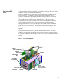
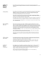
hp rp5400 series of
entry-level unix servers
november 2001
a technical white paper
from Hewlett-Packard
table of contents
introduction to the hp server rp5400 series......................................................................... 3
the hp server product line ............................................................................................. 7
binary compatibility ..................................................................................................... 8
IPF ready..................................................................................................................... 8
IPF transition................................................................................................................ 8
architecture ..................................................................................................................... 9
low-latency memory access ........................................................................................... 11
speeds and feeds......................................................................................................... 11
I/O subsystem design................................................................................................... 13
internal removable media ............................................................................................. 16
scalability.................................................................................................................... 16
rp5400 series industrial design and packaging................................................................... 17
racking density ............................................................................................................ 17
high availablity slider rails ............................................................................................ 17
cabinet spacing requirements........................................................................................ 17
standalone/deskside configuration ................................................................................ 17
high availability ............................................................................................................... 18
redundant, hot-swap power supplies.............................................................................. 18
redundant, power input protection................................................................................. 19
redundant, hot-swap cooling......................................................................................... 19
main memory—advanced ECC and party ...................................................................... 20
memory chip spare technology...................................................................................... 20
hot-plug disk drives ...................................................................................................... 20
hot-plug PCI I/O slots ................................................................................................... 21
dynamic processor deallocation and resilience ............................................................... 21
CPUs............................................................................................................................... 24
Processor upgrades ...................................................................................................... 24
CPU roadmap for the future .......................................................................................... 24
manageability and support ............................................................................................... 24
event notification.......................................................................................................... 24
event monitoring service (EMS)...................................................................................... 24
extended fault management system................................................................................ 25
system platform monitor................................................................................................ 26
built-in web console...................................................................................................... 26
LAN console................................................................................................................ 27
ASCII consoles............................................................................................................. 27
remote access.............................................................................................................. 27
self diagnosis............................................................................................................... 27
online and offline diagnostics........................................................................................ 27
for more information..................................................................................................... 29
2
introduction to the
hp server rp5400
series
In today’s economy, whether you’re managing your own IT infrastructure or hosting someone else’s,
you have to operate with a faster time-to-solution, within budgetary constraints, and with the highest
standards for customer service and operational efficiency.
The HP server rp5400 series give you the fastest and most reliable means to succeed in this new
business environment. The rp5400 series consists of four products that deliver the proven
performance, scalability, and high availability capabilities of UNIX – without high maintenance
requirements and costs. And they give you plenty of room to grow. You can start with a low-price
entry point and scale up to the leading 4-way UNIX performance – in the same form factor.
The rp5400 series is made up of four different servers, each with a unique ability to match your
computing needs. The rp5400 is a 2-way system with time-proven, cost effective PA-RISC
technology. The rp5430 is a 2-way system offering the latest PA-8700 processors and the same
high performance core electronics found in hp’s midrange servers. The rp5450 is similar to the
rp5400, yet it scales to 4-way workloads. The rp5470 is the high performance flagship of the
lineup. It supports up to 4-way PA-8700 processing power and industry leading memory and I/O
bandwidth.
All four members of the rp5400 series use the same rack-optimized 7U package. This allows
seamless scalability with simple in-box upgrades between servers in the series. Additionally, the
rp5400 series was designed for board-swap upgrades to the next generation of Itanium processors.
All together, the rp5400 series offers the Industry’s best 1-4 way lineup with unparalleled investment
protection.
Figure 1.1 A front view of the rp54x0
CPU support
modules
Memory
16 slots
Platform
monitor
Redundant,
hot-swap fans
4-way PA-8700
CPUs
Redundant,
hot-swap power
supplies
Core I/O
Ultra2 SCSI, 100Base-T,
RS-232 and LAN Console
Ultra2 SCSI
hot-plug disks
Removable
media slot
Hot-Plug I/O
10 PCI slots
3
The exploded view reveals the location of major components, as well as the mechanical
and architectural features of the rp5400 series. The server is partitioned into two main electrical
assemblies—the system board and the I/O backplane, and into three main volumes—processor
and memory, I/O and disk, and power.
Looking at the front face, three hot-swap power supply bays are located in the lower left corner.
To the right, a peripheral bay provides space for four hot-plug disks and one removable media
device (either DVD-ROM or DDS-3). Directly above the power supply bays is the first of eight hotswap cooling fans.
The right side of the system houses the I/O card bay. There are ten PCI I/O slots available.
Two pairs of fans located here provide cooling for the I/O bay as well as the peripheral bay.
The opening at the top provides access to the system board, which supports the four CPUs,
sixteen dual inline memory module (DIMM) slots, two processor support modules, and platform
monitor board. The core I/O is located at the rear of the system.
rp5400 features at-a-glance
• 1 or 2 PA-8500 or PA-8600 64-bit
CPUs
• 540 MHz, 440MHz, and 360MHz
CPUs
• IA-64 ready
• Up to 8GB of memory
• 5 hot-plug (66MHz × 64-bit) PCI I/O
slots
• Independent PCI buses for I/O slots
• N+1 power and cooling
• 4 hot-plug disk drives
• Removable media bay: DVD-ROM or
DDS-3
• 1.3GB/s system bus bandwidth
• 1.6GB/s I/O bus bandwidth
• 1.3GB/s memory bus bandwidth
• 64-bit HP-UX 11.0 & 11I
• In-box upgrade to rp5450
• Board-swap upgrade to rp5430 and
rp5470
• High-density 7-EIA-unit, 19-inch
rackmount package or pedestal
4
rp5450 features at-a-glance
• 1 to 4 PA-8500 or PA-8600 CPUs
• 540MHz, 440MHz, & 360MHz
CPUs
• IA-64 ready
• Up to 16GB of memory
• 10 PCI I/O slots (six hot-plug 66MHz
× 64-bit, four 33MHz × 64-bit)
• 6 independent PCI buses for I/O slots
• N+1 power and cooling
• 4 hot-plug disk drives
• Removable media bay: DVD-ROM or
DDS-3
• 1.3GB/s system bus bandwidth
• 2.1GB/s I/O bus bandwidth
• 1.3GB/s memory bus bandwidth
• 64-bit HP-UX 11.0 and 11I
• High-density 7-EIA-unit, 19-inch
rackmount package or pedestal
rp5430 features at-a-glance
• 1 to 2 PA-8600 or PA-8700 CPUs
• 750MHz, 650MHz, and 550MHz
CPUs
• High-performance “Stretch” core
electronics complex (leveraged from
rp7400)
• IA-64 ready
• Up to 8GB of memory
• 5 PCI I/O slots (all are hot-plug
66MHz × 64-bit)
• 5 independent PCI buses for I/O slots
• N+1 power and cooling
• 4 hot-plug disk drives
• Removable media bay: DVD-ROM or
DDS-3
• 4.3GB/s system bus bandwidth
• 2.1GB/s I/O bus bandwidth
• 4.3GB/s memory bus bandwidth
• 64-bit HP-UX 11.0 & 11I
• High-density 7-EIA-unit, 19-inch
rackmount package or pedestal
rp5470 features at-a-glance
• 1 to 4 PA-8600 or PA-8700 CPUs
• 750MHz, 650MHz, and 550MHz
CPUs
5
• High-performance “Stretch” core
electronics complex (leveraged from
rp7400)
• IA-64 ready
• Up to 16GB of memory
• 10 PCI I/O slots (eight hot-plug,
two non-hot-plug; all are
66MHz × 64-bit)
• 9 independent PCI buses for I/O slots
• N+1 power and cooling
• 4 hot-plug disk drives
• Removable media bay: DVD-ROM or
DDS-3
• 4.3GB/s system bus bandwidth
• 3.2GB/s I/O bus bandwidth
• 4.3GB/s memory bus bandwidth
• 64-bit HP-UX 11.0 & 11I
• High-density 7-EIA-unit, 19-inch
rackmount package or pedestal
6
The rp5400 series is the entry-level cornerstone of the business-critical proven hp server product
line. HP servers are #1 among UNIX® servers for reliability, scalability, availability, and
price/performance. This robust product line addresses the major computing challenges
customers face today in online transaction processing (OLTP), electronic commerce (ECOM),
Internet/intranet serving (Web), enterprise resource planning (ERP), supply chain management
(SCM), and technical applications.
At the low-end, affordable A-Class and rp5400 series servers effortlessly handle Internet
workloads and enterprise-size applications. Both platforms also add leadership
price/performance and include bundled Internet software solutions.
In the midrange, the rp8400 and rp7400 deliver the high-performance, compact Internet-era
UNIX server platform that today’s IS executives are demanding. With up to 16 PA-8700
processors, the hp server midrange lineup provides the robust performance and scalability
needed for the most demanding workloads.
With exceptional OLTP performance, availability, scalability, and manageability, the HP 9000
Superdome has become the pacesetter for high-end computing. Superdome, coupled with
HP’s always-on infrastructure strategy provides UNIX application performance and Internetcritical high availability to help you meet the rigorous demands of e-services and systems
consolidation, as well as large-scale, highly complex technical modeling and simulations.
All of hp’s UNIX® servers provide excellent investment protection with a smooth transition path to
future PA-RISC and/or IA-64 architectures. So whether your business requires cutting-edge eservices, systems consolidation, or a host of other solutions, our power-packed servers are
business-critical proven and ready to meet the challenge—today and tomorrow.
PA-8700
Figure 1.2 The industry’s strongest UNIX lineup—top to bottom
high-end
PA-8700
mid-range
Itanium
Superdome
PA-8700
rp8400
rp7400
rx9610
entry-level
A-class
hp unix server
family
rp5430 & rp5470
Itanium
new
PA-8700
the hp server product
line
rx4610
the best server family in the world
7
binary
compatibility
The rp5400 series supports the 64-bit HP-UX 11 operating system. With HP-UX 11, HP maintains
its long-standing tradition of providing the industry’s best record of investment protection. HP-UX
provides forward binary compatibility, in which a fully bound application developed on an earlier
version of HP-UX is ensured to run smoothly on HP-UX 11. Thus, current 32- and 64-bit applications
can run without requiring recompilation.
IPF ready
The rp5400 series was designed for several generations of PA-RISC and is upgradeable to future
releases of Intel’s® Itanium™ Family of Processors (IPF). When the McKinley version of IPF is released
in 2002, hp will offer a board-swap upgrade to move any rp5400 series product or any legacy
hp9000 L-Class product to the IPF architecture.
IPF is based on Explicitly Parallel Instruction Computing (EPIC), a new “architecture technology”
invented by hp labs. The EPIC architecture breaks through the sequential nature of today’s RISC and
CISC processor architectures by allowing the software to communicate explicitly to the processor
when operations can be done in parallel. EPIC serves as the enabler for future high-performance
chips by providing explicit parallelism, massive resources, and inherent scalability not available with
conventional RISC architectures. Increased performance is realized by reducing the number of
branches and branch mispredicts, and by reducing the effects of memory-to-processor latency.
IPF transition
For the vast majority, the transition to IPF will be simple and seamless. For customers who require
additional assistance, HP will provide transition services around the world to help make this upgrade
as smooth as possible. HP can provide assistance every step of the way, from assessment and design
to verification and deployment. Consult the Itanium section of hp’s web page for further information.
8
Figure 2.1 shows the relationship of the rp5470 main blocks and the buses that connect them. The
rp5470 uses the “Stretch” high-performance core electronics complex (CEC), which is also used in
the midrange rp8400 server. This CEC, specifically designed for demanding Internet workloads,
brings unprecedented levels of bandwidth and performance to the 4-way entry-level market.
architecture
Two runway buses, both running at 133MHz, provide 4.3GB/s of bandwidth to four PA-8700 or PA8600 processors. The low latency memory controller provides 4.3GB/s of memory bandwidth to two
8-slot memory extenders. The I/O controller provides twelve 250MB/s data channels, for an
aggregate bandwidth of 3.2GB/s distributed among the 10 PCI slots and multi-function core I/O.
The rp5430 architecture is similar to the rp5470. However, only half of the processor, memory, and
I/O slot capacity is utilized.
Figure 2.1 rp5470 architecture
Memory
slots
Hot-Plug PCI
Twin Turbo slots
Hot-Plug PCI
Turbo slots
Shared
PCI slots
PA-8700
CPU
PA-8700
CPU
PA-8700
CPU
System Bus
Very Low
Latency
Memory
Controller
PA-8700
CPU
System Bus
Ultra2 SCSI
10/100Base-TX
Local
RS-232
Remote
Console
RS-232
Gen
Console
RS-232
10/100Base-TX LAN console
Standard
Multifunction DB-25 port
Core I/O
SCSI2
Optional DVD or
DAT internal
removable media
Optional internal hot-plug
Ultra2 SCSI disks
System Management Ports
System Speeds and Feeds
System bus bandwidth
Memory bus bandwidth
I/O bandwidth total
4.3GB/s
4.3GB/s
3.2GB/s
9
Figure 2.2 is a block diagram of the rp5450 architecture. The rp5450 uses the “Astro” CEC, which
was specifically designed to provide no-compromise features and performance at a low-end price
point. Integrated within the single “Astro” chip is the memory and I/O controllers, with several
peripheral application-specific integrated circuits (ASICs) to control and drive the specific I/O and
memory buses.
The integrated rp5450 CEC design contributes to a significant reduction in memory latency over that
found in competitive systems. The memory controller supports two sets of integrated 8-slot memory
arrays, providing a total of sixteen DIMM slots.
The rp5450 uses a single 82.5MHz runway bus to provide 1.3GB/s of bandwidth to four PA-8600
or PA-8500 processors. The I/O controller in the rp5450 provides eight 250MB/s data channels.
This means an aggregate bandwidth of 2.1GB/s is available to the PCI slots and multi-function core
I/O.
The rp5400 architecture is similar to the rp5450. However, only half of the memory, processor, and
I/O capacity is utilized.
Figure 2.2 rp5450 architecture
Memory
slots
PA-8600
CPU
PA-8600
CPU
Hot-Plug PCI
Turbo slots
PA-8600
CPU
Very Low
Latency
Memory
Controller
Shared
PCI slots
Standard
Multifunction
Core I/O
System Bus
Ultra2 SCSI port
10/100Base-TX port
System
RS-232
RS-232
RS-232
10/100Base-TX LAN console port
DB-25 port
Local Console
Remote Console
Gen Purpose
SCSI2
Optional DVD or
DAT internal
removable media
PA-8600
CPU
Optional internal
hot-plug Ultra2
SCSI disks
Management
Ports
System Speeds and Feeds
System bus bandwidth
Memory bus bandwidth
I/O bandwidth total
1.3GB/s
1.3GB/s
2.1GB/s
10
low-latency
memory access
All four systems in the rp5400 series have sixteen memory slots. The rp5400 and rp5450 have all
sixteen slots laid out on the main system board. The rp5430 and rp5470, on the other hand, use
two 8-slot memory carrier boards. The memory for both systems is connected to the CEC through a
low-latency/high-bandwidth bus. With approximately half the latency of HP’s previous generation KClass server, the rp5400 series can supply the CPUs with requested data in a fraction of the time of
competitive systems.
The rp5400 series uses state-of-the-art SyncDRAM technology available in 256MB, 512MB, 1GB,
and 2GB DIMM pairs, all with advanced Error Checking and Correcting (ECC) protection to detect
and correct single-bit errors. The rp5470 and rp5450 support up to 16GB of total system memory.
The rp5400 and rp5430 support up to 8GB of memory. All sixteen memory slots are active in the
rp5400 and rp5430. These two systems will not boot, however, if more than 8GB of memory is
loaded. So plan your memory configurations appropriately.
The “Stretch” core electronics complex used in the rp5430 and rp5470 supports memory chip
spare. This high availability technology detects and corrects DRAM failures on memory DIMMs.
With chip spare, any single DRAM chip can fail and the system will continue to operate normally.
Chip spare is not supported on the 256MB DIMM pair, nor is it supported on the rp5400 of
rp5450.
To decrease memory latency and improve performance, the memory address lines are buffered three
times: once on the system board to drive each memory carrier, once on the memory carrier to drive
banks of DIMMs, and again on each DIMM before driving the memory components.
speeds and feeds
Tables 2.1, 2.2, and 2.3 show the theoretical maximum bandwidth for various system buses. This is
defined as the bus width multiplied by the frequency and number of buses.
Table 2.1 Maximum bandwidth for rp5470 system buses
# of buses (or controllers)
maximum bus bandwidth
aggregate bus bandwidth
twin-turbo PCI slots
2
500MB/s
1GB/s
turbo PCI slots
6
250MB/s
1.5GB/s
shared PCI slots
1
250MB/s
250MB/s
core I/O
1
250MB/s
250MB/s
I/O subsystem
1 (controller)
3.2GB/s
3.2GB/s
memory subsystem
2
2.15GB/s
4.3GB/s
CPU buses
2
2.15GB/s
4.3GB/s
11
Table 2.2 Maximum bandwidth for rp5430 system buses
# of buses (or controllers)
maximum bus bandwidth
aggregate bus bandwidth
twin-turbo PCI slots
2
500MB/s
1GB/s
turbo PCI slots
3
250MB/s
750MB/s
core I/O
1
250MB/s
250MB/s
I/O subsystem
1 (controller)
3.2GB/s
3.2GB/s
memory subsystem
2
2.15GB/s
4.3GB/s
CPU buses
2
2.15GB/s
4.3GB/s
Table 2.3 Maximum bandwidth for rp5450 system buses
# of buses (or controllers)
maximum bus bandwidth
aggregate bus bandwidth
turbo PCI slots
6
250MB/s
1.5GB/s
shared PCI slots
1
250MB/s
250MB/s
core I/O
1
250MB/s
250MB/s
I/O subsystem
1 (controller)
2.1GB/s
2.1GB/s
memory subsystem
1
1.3GB/s
1.3GB/s
CPU buses
1
1.3GB/s
1.3GB/s
Table 2.4 Maximum bandwidth for rp5400 system buses
# of buses (or controllers)
maximum bus bandwidth
aggregate bus bandwidth
turbo PCI slots
5
250MB/s
1.25GB/s
core I/O
1
250MB/s
250MB/s
I/O subsystem
1 (controller)
2.1GB/s
2.1GB/s
memory subsystem
1
1.3GB/s
1.3GB/s
CPU buses
1
1.3GB/s
1.3GB/s
12
I/O subsystem design
The rp5470 contains ten PCI I/O slots. The top eight slots have hot-plug capabilities under HP-UX
11i. The eight hot-plug slots all have independent I/O channels. This independent design prevents
slow cards from affecting the performance of a fast card. Not only does independence provide great
performance, it also provides error containment. For example, if a card hangs in slot 9, cards in slots
0–8 will still function properly. The highest performing cards should always be placed in these slots.
The first two hot-plug slots are Twin-Turbo slots, meaning they each have two dedicated 250MB/s
channels or a total of 500MB/s per slot. These two slots should be reserved for the highest
performing I/O cards, such as fibre channel, gigabit ethernet, or Hyperfabric controllers. The
remaining six hot-plug slots are Turbo slots, each with a single 250MB/s channel.
In addition to the eight hot-plug slots, the rp5470 has two shared PCI slots. These slots share a single
250MB/s channel.
All ten of the rp5470 I/O slots use HP-developed adaptive signaling technology to automatically
match an I/O card’s appropriate speed and data width. Therefore, all slots will accept 64- or 32-bit
cards running at either 33 or 66MHz.
The rp5430 I/O subsystem is similar to the rp5470. In the rp5430, however, the shared PCI slots
and three of the Turbo slots are not active. Both Twin Turbo slots, three additional Turbo slots, and
the multifunction core I/O are available in the rp5430.
Figure 2.3 rp5470 I/O subsystem
Hot-Plug PCI
Twin Turbo slots
Hot-Plug PCI
Turbo slots
• All Slots Accept 32- and 64-bit (33- and 66MHz) PCI Cards
• Data channel (8-bit data)
– 250MB/s
– 133MHz
– Full parity checking
Shared
PCI slots
Ultra2 SCSI port
10/100Base-TX
port
Standard
Local Console
RS-232
System
Multifunction DB-25 port
Remote Console
RS-232
Gen Purpose
Core I/O
RS-232
10/100Base-TX LAN console port
SCSI2
Optional DVD or
DAT internal
removable media
Management
Ports
Ultra2 SCSI
Optional internal
hot-plug disks
13
The rp5450 also has ten PCI I/O slots. The top six Turbo slots, labeled slots 6–11, have hot-plug
functionality in HP-UX 11i. Each of these six Turbo slots supports 64-bit × 66MHz PCI cards
running at full speed. These slots are connected to the I/O controller via six independent/dedicated
high-speed 250MB/s channels. This independent design prevents slow cards from affecting the
performance of a fast card. Not only does independence provide great performance, it also
provides error containment. For example, if a card hangs in slot 9, cards in slots 0–8 will still
function properly. The highest performing cards should always be placed in these slots.
The next four slots run at 64-bit × 33MHz. 66MHz cards plugged into these slots will be throttled
back to 33MHz. These slots share a single 250MB/s channel and are not hot-plug capable. The
last 250MB/s channel supports the multifunction core I/O.
The rp5400 I/O subsystem is similar to the rp5450. In the rp5400, however, the shared PCI slots
and one of the Turbo slots are not active. Five Turbo slots, as well as the multifunction core I/O is
available in the rp5400.
Hot-Plug PCI
Turbo slots
Shared
PCI slots
I/O Controller
Figure 2.4 rp5450 I/O subsystem
• All Slots Accept 32- and 64-bit (33- and 66MHz) PCI Cards
• Data channel (8-bit data)
– 250MB/s
– 133MHz
– Full parity checking
Ultra2 SCSI port
10/100Base-TX port
Local Console
RS-232
System
Remote Console RS-232
Gen Purpose
RS-232
10/100Base-TX LAN console port
Standard
Multifunction DB-25 port
Core I/O
SCSI2
Ultra2 SCSI
Optional DVD or
DAT internal
removable media
Optional internal
hot-plug disks
Management
Ports
14
PCI is the optimized, industry-standard I/O bus. Tables 2.5 through 2.8 summarize the PCI slots for
each of the systems in the rp5400 series.
Table 2.5 rp5470 PCI I/O
# of slots
hot plug
bandwidth
per channel
bus width
signaling
speed
slot
keying
adaptive
signaling
twin turbo
2
Yes
500MB/s
64 bits
66 & 33
MHz
5 volts
Yes
turbo
6
Yes
250MB/s
64 bits
66 & 33
MHz
5 volts
Yes
shared
2
No
250MB/s
64 bits
33MHz
5 volts
Yes
signaling
speed
slot
keying
adaptive
signaling
Table 2.6 rp5430 PCI I/O
# of slots
hot plug
bandwidth
per channel
bus width
twin turbo
2
Yes
500MB/s
64 bits
66 & 33
MHz
5 volts
Yes
turbo
3
Yes
250MB/s
64 bits
66 & 33
MHz
5 volts
Yes
signaling
speed
slot
keying
adaptive
signaling
Table 2.7 rp5450 PCI I/O
# of slots
hot plug
bandwidth
per channel
bus width
turbo
6
Yes
250MB/s
64 bits
66 & 33
MHz
5 volts
Yes
shared
4
No
250MB/s
64 bits
33MHz
5 volts
Yes
signaling
speed
slot
keying
adaptive
signaling
66 & 33
MHz
5 volts
Yes
Table 2.8 rp5400 PCI I/O
turbo
# of slots
hot plug
bandwidth
per channel
bus width
5
Yes
250MB/s
64 bits
15
internal
removable
media
The rp5400 series contains a single removable media bay that can accommodate either a DVDROM or DDS-3The media bay is supported by one of two SCSI controllers located within the core
I/O.
A dedicated single-ended (SE) SCSI channel connects the media bay to the controller. The
removable media bay does not support hot-plug capability. The DVD-ROM drive provides access
of up to 650MB of data from one disk. The DVD-ROM drive provides enhanced features while
preserving backward read compatibility with CD-ROM. Data transfer rates of up to 6.75MB/s are
achieved with the DVD format; 4.8MB/s can be achieved with the CD format.
The DDS-3 drive offered with the L-Class provides storage capacity of up to 12GB on a single tape.
The L-Class DAT drive can store up to 7.2GB of data per hour, and automatic read-after-write
verification helps to ensure the integrity of stored data. Read-write backward compatibility with
DDS-1 and DDS-2 allows continued use of existing archive tapes.
scalability
The rp5400 series is designed without tradeoffs in CPU, memory, internal storage, or I/O
expandability to offer the best scalability in the market.
• CPU upgrades—With its entry-level configuration of one CPU and single-CPU increments
available up to four processors, the rp5400 series offers great flexibility to cover a wide range of
performance points. Currently the rp5400 and rp5450 offer PA-8500 360MHz and 440MHz
processors, as well as 540MHz PA-8600 processors. The rp5430 and rp5470 offer 550MHz
PA-8600 processors, as well as 650MHz and 750MHz PA-8700 processors.
• Memory upgrades—The rp5400 series memory subsystem is also designed for scalability. With
16 available slots, the servers range from a minimum of 256MB to a maximum of 16GB of
main memory.
• Internal Storage—The rp5400 series supports up to four internal hot-plug disk drives, which can
be either half-height or low-profile form factors. Current disk offerings include 18, 36, and 73GB
Ultra160 disk drives. The maximum internal storage is 292GB, via four 73GB drives.
16
rp5400 series
industrial
design and
packaging
The rp5400 series has been designed to fit into environments ranging from data centers to
deskside. The industrial design is coordinated with other hp servers and peripherals for a consistent
appearance.
racking density
The rp5400 series is designed to provide unprecedented performance density that easily adapts to
different environments. At 7 EIA units (EIA unit= 1.75 inches), up to five L-Class units can be
installed into a single 2-meter HP cabinet. With the high cost of computer room floor space,
this small footprint dramatically lowers total cost of ownership.
The rp5400 is supported in A490xA and A189xA cabinets. When using the High Availability
Slider rail, bolt-on Anti-tip feet are required. When using the slider in A189xA cabinets, ballasts are
required (see the HP 9000 Configuration Guide for details).
The rp5400 is also supported in a variety of third-party, non-HP racks and cabinets. Please refer to
the HP 9000 Enterprise Servers Configuration Guide for the latest list of qualified third-party racks.
Note—Dimensions for Rack configuration: H= 12.25 inches (311 mm), D= 30.5 inches (775 mm),
W= 19 inches (482 mm).
high availability
slider rails
There are two rail options, static or slider, available for racking the rp5400 series into an HP
cabinet. The High Availability (HA) Slider rails were designed to allow easy service access to the
system, as well as to enable the hot-plug capability of the I/O slots and hot-swap of four fans in the
side cavity. With the HA slider rail the rp5400 series can be completely serviced without removing
it from the rack, thus allowing side-by-side racks of systems to be completely supported without
sacrificing floor space for side access to the system. The slider rails also contribute to a 100%
improvement in “mean time to repair” over D- and K-Class servers. The High Availability Slider rails
are highly recommended.
Note—The slider mechanism occupies 1 EIA unit of rack space. When used with the rp5400
series, the combination will occupy 8 EIA units of rack space.
Static rails do not consume EIA space within the cabinet, therefore leaving more EIA space for
peripherals. However, using static rails prohibits hot-plug of the I/O cards and hot-swap of the
I/O bay fans.
cabinet spacing
requirements
The rp5400 series requires a minimum of 24 inches (61 cm) of free space in both the front and
rear of the cabinet for proper ventilation. During product installation and servicing, a total of 32
inches (82 cm) of free space is needed at the front of the cabinet.
The depth of HP A490xA cabinets is 39 inches (99 cm). Therefore, a minimum of 87 inches
(221 cm) of total space is needed for each cabinet during normal operation. An additional
8 inches (21 cm) is needed during installation and servicing.
standalone/
deskside
configuration
The rp5400 series is also available in a standalone configuration when a cabinet is not desired.
The standalone system is ideal for an office environment, under a desk, or on a shelf. The
standalone configuration utilizes the same internal chassis and front plastic bezel as the racked
version. However, a sheet metal cover, base, and casters are added for functionality and
aesthetics. Casters can be removed when not desired.
Note—Dimensions for standalone/deskside configuration: H= 14.5 inches (368 mm),
D= 30.5 inches (775 mm), W= 19 inches (482 mm).
17
high availability
The rp5400 series has numerous high availability features that are unmatched in the entry-level
server market—features such as redundant hot-swap fans and power, hot-plug I/O and disks,
memory scrubbing and page deallocation, memory chip spare, independent PCI slots, failure
avoidance and notification capability, and MC/Serviceguard support. These features improve the
availability level of the total system and are introduced in this section.
redundant, hotswap power
supplies
HP power supplies have a long history of excellent reliability, and the redundant power supply
option increases HP’s commitment to even higher reliability and availability.
The rp5400 series power subsystem holds a maximum of three hot-swap power supplies. These
supplies are located in the very front of the server. Each supply is capable of sustaining 930 watts of
output. The rp5400 and rp5430 come standard with one power supply; a second and even third
supply can be added for redundancy. The rp5450 and rp5470 come standard with two power
supplies; a third supply can be ordered for redundancy. Each power supply has its own power cord,
which provides protection against losing the power from a single cord or breaker. To maximize
availability, the power cords should be plugged into separate breakers whenever possible.
Because of the hot-swap capability, in the event of a power supply failure, the faulty supply can be
removed and replaced without notifying the system. This, of course, is assuming that an N+1
condition exists.
Exchanging a power supply in a running system involves opening the front plastic bezel. The failed
power supply is easily identified and removed. The power supply is exchanged with a good one
and the door is then closed to finish the process. The system will log another chassis code to indicate
that redundancy is re-enabled. It is that simple.
There is another advantage for those customers with rigorous preventative maintenance programs.
While the server continues to operate, the power supplies can be removed one-at-a-time and dust
buildup can be vacuumed using proper electrostatic discharge (ESD) procedures.
18
redundant power
input protection
Figure 3.1 contains a diagram of the rp5400 series power subsystem. This section explains how
customers can utilize these capabilities to achieve different levels of power input protection.
Figure 3.1 power subsystem
front
3 hot-swap
power supplies
for N+1 or N+2
protection
Redundant
power supplies
are optional
top view
back
power supply
power supply
power supply
line filters
∅C
∅B
∅A
3 power inputs (can be separate phases) for N+1
or N+2 protection against AC power circuit failure
The server has three AC input line cords to reduce single points of failures. Each line cord supplies
power to one of the three internal power supplies. The system is designed to operate on nominal
100–240 VAC and 50- or 60-Hz power without line-select switches. Each power supply can draw
up to 930 watts.
The rp5400 and rp5430 operate with a minimum of one power supply. A second or third supply
can be added for N+1 or N+2 redundancy. The rp5450 and rp5470 require a minimum of two
power supplies – a third can be added for N+1 redundancy. Because the servers will continue to
operate with two of the three supplies functioning, many possibilities exist for the customer to
configure the AC input depending on the level of protection desired.
• If the site has very stable AC power, all three line cords could be plugged into the same power
grid. For additional protection, a single un-interruptible power supply (UPS) could be utilized to
supply power to all three cords should primary AC power fail.
• The next higher level of protection is to have three branch AC circuits, one for each AC input.
This reduces the dependencies on single-point breaker failures and common wiring. Additional
protection to this configuration would utilize three smaller UPSs.
• The highest level of protection is to have three electrical utilities each supply a branch circuit.
This approach is expensive but does greatly reduce single points of failures. Large sites with many
systems may find this configuration cost-effective. For ultimate protection of large sites, install a
large UPS on each branch circuit.
19
redundant, hotswap cooling
The rp5400 series contains eight hot-swappable fans to cool system components. The eight cooling
fans (1 front-access, 4 side-access, 3 rear-access) are arranged in an N+1 configuration so any fan
can fail and not affect system uptime. In the event of a fan failure, the faulty fan can simply be
removed and replaced while the server continues to run. The design pairs fans together. If one fan
fails, the other speeds up to ensure adequate system cooling.
In addition, the server monitors ambient temperature and the power consumed within the box to
determine the desired fan speed. The actual speed is determined by sensing the tachometer outputs
from each fan. Digital Phase Locked Loop (DPLL) circuitry is used to adjust the speed of each fan
individually to the desired common speed.
These smart algorithms reduce unnecessary fan noise, power consumption, and wear while
producing a very clear indication of a working cooling subsystem. In the unlikely event of a fan
failure, it will drop out of lock with the DPLL. The server signals a fan failure via chassis codes to the
console and will light an LED on the failed fan assembly.
There is another advantage for those customers with rigorous preventative maintenance programs.
While the server continues to operate, the fans can be removed one-at-a-time and dust buildup can
be vacuumed using proper ESD procedures.
main memory—
advanced ECC
and parity
Data stored in the main memory is protected by error correction code (ECC) and address/control
parity. The ECC design provides memory scrubbing and page deallocation functionality that will
tolerate typical hard single-bit SDRAM failures without requiring DIMM replacement.
The data controllers generate ECC bits and store these ECC bits with the data in the DIMMs. The
256MB, 512MB, and 1GB DIMMs use x4 SDRAMs to store each bit of a word, including its ECC
bits, in a different SDRAM within the DIMM pair. The 128MB DIMMs use x8 SDRAMs. When
reading the data back, the data controllers are able to detect and correct single-bit data errors.
Double-bit errors cannot be corrected. Double-bit data errors are highly unlikely because the data
and ECC bits are stored one-bit-per-SDRAM and multiple SDRAMs would have to be involved in the
error. Hence, a single SDRAM could fail within each DIMM pair and the system would still function.
The system also detects address and control parity errors to prevent data corruption from reading or
writing to the wrong location in main memory. The address controller and each address buffer
generate address and control parity. Each address buffer detects address and control parity
problems and reports it back to the address controller. There are three levels of address buffers as
the address lines fan out. These address buffers are located on the system board and on each
memory carrier on each DIMM.
memory chip
spare technology
Chip spare is the ability of the system to continue to run in the face of any single or multi-bit chip
error on a DRAM. DRAMs are basically n+1 per set of 128 DRAM per memory word. this
functionality is essential in the design of reliable memory systems. Systems without this functionality
are doomed to fail at an alarming rate when compared to hp servers.
Both the rp5430 and rp5470 support chip spare. The 256MB DIMM pair (product A5554A) does
not support chip spare. To ensure maximum memory availability, the rp5430 and rp5470 should
be configured with 512MB, 1GB, or 2GB memory modules only. The rp5400 and rp5450 do not
have chip spare capabilities.
20
hot-plug disk
drives
The rp5400 series has four embedded SCSI disks accessible from the front of the server. These disks
can be removed and inserted while the server continues to operate. This operation is called “hotplug,” and it is different from “hot-swap.”
During both hot-plug and hot-swap operations, the power remains on and the system continues to
function. However, hot-swap means that the assembly can be removed, added, or replaced without
informing the system. Hot-plug requires the assembly to be de-configured before removal and reconfigured before the system can utilize the newly inserted assembly. Because disks have unique
information stored on them, hot-plug methods are used. Fans and power supplies are hot-swap
assemblies.
Two dual-channel SCSI controllers manage the four internal hot-plug disks. For added availability,
disk pairs are on separate channels as well as separate SCSI controllers. This means that with disk
mirroring, a SCSI controller, SCSI channel, or root disk could fail and the server would continue to
run properly.
The rp5400 series contains circuitry to properly control the disk’s power and reset during the hotplug operation. Either System Administration Manager (SAM) or online diagnostic software (MESA)
can be utilized to effectively de-configure and re-configure the disk.
There is another advantage for those customers with rigorous security programs, which require disks
mechanisms to be completely removed and isolated in a disaster and theft-safe environment.
21
hot-plug PCI
I/O slots
The ability to hot-plug PCI cards offers excellent flexibility for adding, reconfiguring, and maintaining
I/O functions while the system continues operations. No reboot is required.
The I/O card bay is located at the right rear of the chassis. The I/O bay supports up to
10 PCI cards. Access to the I/O bay in rackmounted systems utilizing the High Availability Slider is
achieved by sliding the server forward. Special features on the chassis, along with custom rack rails,
allow the unit to move safely and smoothly during online service with all cables still attached. Once
the system is slid into the service position, the I/O bay cover can be removed to gain side access
to the PCI cards. In the standalone configuration, the outer shell is removed to gain access to the
I/O bay.
The rp5470 supports ten PCI I/O slots, and eight of those slots are hot-plug ready. The rp5450
supports ten PCI I/O slots, and six of those slots are hot-plug ready. Each of the hot-plug slots
support 64-bit × 66MHz PCI cards running at full speed and are connected to the I/O controller
via independent high-speed 250MB/s channels. This independent design prevents slow cards from
affecting the performance of a fast card. Not only does independence provide great performance, it
also provides error containment. For example, if a card hangs in slot 10, cards in all other slots will
still function properly. The highest-performing cards should always be placed in these independent
slots.
The rp5400 & rp5430 support five PCI I/O slots. Ten physical slots are available, but only five of
the slots are functioning electrically. All five slots support hot-plug actions.
The PCI cards are spaced on a .9-inch pitch, to allow for special hot-plug features and increased PCI
reliability. Extra airflow holes between bulkheads have more than doubled PCI airflow. Between the
PCI slots, PCB separators prevent electrical shorting and exposure to hazardous energy during hotplug installation and removal. Locking features are designed into the main chassis to eliminate the
need for individual PC board bulkhead screws, thus removing a potential electrical safety hazard.
Hot-plugging I/O cards have both hardware and software components. The hardware requirements
are met by the electronics on the I/O backplanes and by mechanical design in the I/O cardcage.
Bus idling, slot-to-slot electromechanical isolation, per-slot power and reset control, and visual
indicators are all components of the total hot-plug hardware solution. With associated software, any
card located in a hot-pluggable PCI slot can be removed, replaced, or added without power cycling,
rebooting the system, or impacting the operation of other I/O transactions.
Please note that software support for this feature is available in HP-UX 11i, but not in HP-UX 11.0.
dynamic
processor
deallocation
and resilience
Every multi-CPU server with properly loaded HP-UX 11 has the capability for Dynamic Processor
Deallocation and Resilience. Incorporated into HP’s version 11 of HP-UX is the capability to take a
processor out of service while the system is running without interruption to applications. This
technology is referred to as Dynamic Processor Deallocation. Once a processor is deallocated, the
HP-UX operating system will migrate all application processes that are currently scheduled on that
processor to other active processors. Note that if the processor has been assigned to handle
interrupts for any I/O drivers, it will continue to do so while it is deallocated.
The rp5400 series PA-RISC processors have the ability to detect and correct single-bit cache errors.
The embedded event monitoring service (EMS) monitors the rate of correctable errors in each
processor’s on-board cache. These errors are manifested as Low Priority Machine Checks (LPMCs).
While occasional correctable errors are to be expected in the on-board cache, too many of these
errors in a short period of time indicate an increased likelihood that a non-correctable cache error
could occur. The EMS LPMC monitor will continuously monitor the rate at which LPMCs are occurring
and dynamically deallocate a processor, using the Dynamic Processor Deallocation facility. This
technology is referred to as Dynamic Processor Resilience.
22
CPUs
The rp5400 series supports PA-8700, PA-8600, and PA-8500 processors. In the future, Itanium
Processor Family (IPF) CPUs will also be supported.
processor
upgrades
The rp5400 series provides outstanding investment protection and lasting value with a system
infrastructure that is designed to accommodate several generations of processor upgrades. To
enable in-chassis processor upgrades, several areas of the server needed to have headroom
designed into them. This added capacity avoids bottlenecks and ensures that the additional
performance of new processors results in comparable system-level performance increases.
CPU roadmap for
the future
The CPU roadmap in Figure 4.1 illustrates HP's commitment to long-term processor and architecture
innovation, enabling HP to provide the massive resources needed for future computing requirements.
Figure 4.1 HP’s CPU roadmap
hp’s microprocessor roadmap
a commitment to pa-risc and itanium
tbd
Madison
PA-8900
performance
Deerfield
McKinley
PA-8800
PA-8700
Itanium
PA-8600
PA-8500
PA-8200
PA-8000
‘96
‘98
‘00
‘02
‘04 future
Customers can continue to rely on binary compatibility across the PA-RISC family, enabling seamless
interoperability with legacy applications on HP systems. Binary compatibility protects customers’
investments, enabling rapid growth and adoption of new technology infrastructures. In addition,
customers can use existing applications and operating systems with advanced processor technology
for distinct performance improvements.
HP will continue to support binary compatibility through the introduction of IPF-based systems. As a
result of HP’s co-development work with Intel on Explicitly Parallel Instruction Computing (EPIC), the
technology foundation for IPF, today’s HP-UX, Windows, Linux, and MPE/iX applications will run
unchanged on IPF. For maximum performance, customers can recompile applications without source
changes.
For more technical information on the PA-RISC processors, see the hp server rp7400 white paper.
For more technical information on IPF processors, see the hp server rx4610 white paper.
23
manageability
and support
event notification
The rp5400 series has many features to minimize the effort required to manage one system or an
entire computer room. The server simplifies system management in several aspects: event notification,
automatic error handling, power monitoring, and the user interface to system management.
For an operator who is physically present, there are two ways to receive event notification. The
simplest and easiest are the status LEDs on the front of the system. These five LEDs allow rapid
verification of system status via a quick glance at the system. The five LEDs each have a specific
meaning:
• Power—power is present and on, and power supplies are functioning properly
• Remote—remote console is enabled
• Run—system is up and running
• Attention—occurrence of a non-catastrophic event; e.g., failure of an N+1 component
• Fault—occurrence of a catastrophic system event
In addition to the five specific meanings of the LEDs, related system status is encoded based on
whether the LED is on solid or flashing; examples include unexpected reboot system recovered,
operating system not running, and operator intervention required.
event monitoring
service (EMS)
HP EMS is a system monitoring application designed to facilitate remote/centralized real-time
monitoring and error detection for HP products in the enterprise environment. This framework
provides centralized management of hardware devices such as the rp5400 series servers and
system resources, and it provides immediate notification of hardware failures and system status. HP
EMS can receive data on unusual activity, add information on the problem's source, and provide
recommendations on problem resolution.
HP EMS consists of a set of system and network monitors within a monitoring environment. This
monitoring framework has an easy-to-use interface and provides a mechanism for monitoring
resources, registering monitoring requests, and sending notification when resources reach userdefined critical values.
How it works:
• A hardware event monitor detects abnormal behavior in one of the hardware resources (devices)
it is monitoring.
• The hardware event monitor creates the appropriate event message, which includes suggested
corrective action, and passes it to the EMS.
• EMS sends the event message to the system administrator using the notification method specified
in the monitoring request (for example: e-mail, message to the console, entry in a system log).
• The system administrator (or Hewlett-Packard service provider) receives the messages, corrects the
problem, and returns the hardware to its normal operating condition.
• If the Peripheral Status Monitor (PSM) has been properly configured, events are also processed by
the PSM. The PSM changes the device status to DOWN if the event is serious enough. The change
in device status is passed to EMS, which in turn alerts MC/Serviceguard. The DOWN status will
cause MC/Serviceguard to failover any package associated with the failed hardware resource.
• Any of the following consoles can be used with EMS to remotely monitor server farms:
HP MC/Serviceguard, CA Unicenter, HP Openview ITO, HP Secure Web Console, and
HP Netserver Toptools.
24
The monitors can also poll hardware, disks, clusters, network interfaces, and system resources
and send information to the framework. An “event” can be simply defined as something you want to
know about—for example, a disk failure or file space dropping below a predefined level.
The primary EMS benefits include:
• Enables efficient and effective system monitoring within a single, comprehensive framework
• Delivers the ability to tailor the monitoring system to fit specific needs
• Provides a wide variety of notification methods through multiple protocols (SNMP traps, TCP, UDP,
OPC Messaging)
• Provides immediate alerts if a component fails, enabling proactive replacement
• Integrates with HP MC/Serviceguard and Serviceguard OPS Edition to provide a complete high
availability solution
extended fault
management
system
The rp5400 series employs a dedicated processor to aid system management and diagnosis. The
Extended Fault Management System can diagnose a system failure even in the unlikely event that the
system is unable to execute code. It allows system power to be remotely turned on or off, and it has
battery backup that even allows diagnosis of power failures. The system interfaces to key
components via an I2C bus to continually monitor the status of system fans, temperature, and power
supplies; it signals the operator for any significant system events.
Major features of the Extended Fault Management System include:
• System console redirection
• Console mirroring
• Configuration of system for automatic restart
• Viewing history log of system events
• Viewing history log of console activity
• Setting inactivity timeout thresholds
• Remote system control
• Power control—remote power on and off
• Viewing system status logs
• Configuration of virtual front panel display
• Event notification to system console, e-mail, pager, and/or HP Response Centers
• Auto system restart
• Virtual front panel display
• Password security (same level as UNIX)
25
system platform
monitor
Closely integrated to the Extended Fault Management System is the system platform monitor. The
system platform monitor controls and monitors system power and cooling. Aspects controlled and
monitored by the system platform monitor are:
• Power supply status and temperature
• System supply voltages—including remote system power on and off
• Total system power consumption
• Individual Processor Support Module status
• External ambient air temperature
• Individual fan speed and status
Various temperatures are monitored to control the system fans, provide thermal warnings, and
prevent permanent damage from overheating by graceful shutdown in over-temperature situations.
(Note that the system fans are run only as fast as necessary to keep the system cool. The fans are
kept in sync with each other, turning at exactly the same rate. This intelligent fan control allows the
L-Class to generate as little noise as possible while maintaining an optimum operating environment
to maximize reliability.)
The power monitor senses the presence of power supplies and the power consumption of system
components to determine if the system is in an N or N+1 power configuration; it can determine:
• Number of bulk power supplies
• Number of CPUs
• Amount of memory present
• Number and power consumption of each installed PCI I/O card
System configuration and health is tracked by the system platform monitor and passed via a
dedicated I2C bus to the Fault Management Processor. This information can be processed as follows:
simply displayed on the system console, logged to an event file, or used to trigger an alert based on
a specific threshold (system temperature, fan status, or power supply status, for example).
built-in web
console
The rp5400 series includes HP’s Secure Web Console to allow management of many systems from a
single Internet browser. The web console is embedded into the fault management processor and can
be accessed through the core 10/100 BaseTX management LAN. The external Secure Web
Console box that shipped with older generation of hp servers is no longer needed. As illustrated in
Figure 5.1, the Secure Web Console allows any Netscape or Explorer browser to be used as a
system console, giving total system access to authorized system administrators anywhere, just as if
they were at an ASCII console. A high level of password protection is used to control access to the
Web console.
Major features of Secure Web Console include:
• System management over the Internet or intranet
• Mirrored access—up to four operators can simultaneously share the same screen and keyboard
• Security—built-in password encryption, data scrambling, and Java™ download protection
• Universal browser-based support for Netscape v.3.0+ and Microsoft Internet Explorer v.3.0+ Web
browsers
• Easy updates of Web console software over the network
• Easy installation—just connect the L-Class console port to a LAN; there is no client software to
install
• Support for HTTP, FTP, TFTP, and other key Internet standards
26
LAN console
The server also provides a LAN console interface using industry-standard telnet connections. Like the
Web console, the LAN console can be used remotely for managing many systems from a single
control center. The telnet interface allows scripts to be used to vastly simplify multiple system
management. Password protection provides a high level of security to control access to the LAN
console, ensuring that only authorized personnel perform system management.
ASCII consoles
For users who wish to locally administer their systems, the rp5400 series provides an RS-232 port to
use for ASCII terminal console connections. Any VT100-capable terminal or emulator can be used as
a local system console.
remote access
As with previous HP server systems, an RS-232 interface for a remote console that is useful for
obtaining help from HP service experts. Customers need only add a modem to allow remote access
via the phone; security is ensured by having to explicitly enable remote console access, which is
protected with a password, and via dial-back phone verification.
self-diagnosis
Many features have been designed into the server to maximize system uptime. There are several
aspects to maximizing uptime: eliminating common single points of failure, allowing the system to
continue running after some errors, and allowing quick identification and servicing of hardware
faults if they do occur.
Besides using traditional diagnostic software, the server also continuously monitors system health
with the platform monitor. Knowing a failure has occurred that reduces N+1 protection is important.
It is important to minimize the risk of downtime by replacing a failed component as soon as possible
to get back to the safety of an N+1 configuration. To enable this, the server provides several
methods of event notification.
The rp5400 series has extensive firmware-based self-tests. These diagnostics are evoked on power
up or reset. The self-tests check for correct system operation prior to booting the operating system.
The firmware diagnostics first check the processors, then processor caches and memory, and finally
I/O devices. Testing complexity increases as more of the system is proven good and more pieces of
the system can be relied upon to increase test coverage on the remaining parts. Self-test failures are
reported to the system console and the support processor, along with failure specifics and
recommended corrective action.
online and offline
diagnostics
The rp5400 also offers traditional online and offline diagnostics to validate system health and
provide extensive system fault coverage.
With online diagnostics, the system is tested while the operating system and applications continue to
run. This allows basic testing of system components that are not currently being used, or in situations
where testing does not prevent continued use of the operating system and applications.
Offline diagnostics provide increased coverage of system components for improved fault isolation
and intensive system testing before returning to production.
27
For More Information
HP product information and technical
documentation is available online at:
http://www.hp.com/go/rp5400
http://www.hp.com/go/rp5430
http://www.hp.com/go/rp5450
http://www.hp.com/go/rp5470
Contact any of our worldwide sales
offices or HP Channel Partners (in
the U.S., call 1-800-637-7740) or at
the following international numbers:
United States of America:
+1 800 637 7740
Canada:
Hewlett-Packard Ltd.
5150 Spectrum Way
Mississauga, Ontario L4W 5G1
+1 905 206 4725
Japan:
Hewlett-Packard Japan, Ltd.
Japan Country H.Q.
3-29-21, Takaido-Higashi, Suginami-ku,
Tokyo, 160-8585 Japan
+81 3 3331 6111
Latin America:
Hewlett-Packard
Latin American Region Headquarters
Waterford Building, 9th Floor
5200 Blue Lagoon Drive
Miami, Florida 33126 USA
+1 305 267 4220
Refer to country phone numbers
Australia/New Zealand:
Hewlett-Packard Australia Ltd.
31-41 Joseph Street
Blackburn, Victoria 3130
Australia (A.C.N. 004 394 763)
+61 3 9272 2895
Asia Pacific:
Hewlett-Packard Asia Pacific Ltd.
17-21/F, Shell Tower
Times Square
1 Matheson Street
Causeway Bay
Hong Kong
+8522 599 7777
Europe/Africa/Middle East:
Hewlett-Packard S.A.
150, Route du Nant-d’Avril
CH-1217 Meyrin 2
Geneva, Switzerland
+41 22 780 81 11
European Multicountry: +41 22 780 81 11
Middle East and Africa: +41 22 780 71 11
European Headquarters: +41 22 780 81 81
For direct country contact call:
Argentina: +541 787 7145
Austria: +43 1 25 000 0
Belgium & Luxembourg: +32 2 778 31 11
Brazil: +5511 7296 8000
Chile: +562 203 3233
Colombia: +571 629 5030
Denmark: +45 45 99 10 00
East Central Europe, CIS, and
Yugoslavia: +43 1 25 000 0
Finland: +358 9 887 21
France: +33 1 69 82 60 60
Germany: +49 7031 140
Greece: +30 1 689 644
Hungary: +36 1 252 7300
Iceland: High Performance Systems hf.
+354 1 67 10 00
Ireland: +353 1 615 8200
Israel: Computation and Measurement Systems
(CMS) Ltd. +972 3 5380 333
Italy: +39 2 92122770
Mexico: +525 326 4600
Netherlands: +31 20 547 6911
Norway: +47 22 7356 00
Poland: +48 22 608 77 00
Portugal: +351 1301 7343
Russia and the CIS, excl. Ukraine:
+7 095 923 5001
Slovenia: +38 61 55 84 72
Spain: +34 1 631 1600
Sweden: +46 8 444 2000
Switzerland: +411 735 7111
South Africa: Hewlett-Packard South Africa
(Pty) Ltd.+27 11 806 1000
Turkey: +90 212 224 5925
United Kingdom: +44 1344 369231
Venezuela: +582 239 4133
Unix is a registered trademark of
The Open Group
Intel is a U.S. registered trademarks of Intel
Corporation.
Microsoft, Windows, and Windows NT are U.S.
registered trademarks of Microsoft Corporation.
Netscape is a U.S. trademark of Netscape
Communications Corporation.
Java is a U.S. trademark of Sun Microsystems,
Inc.
Technical information contained in this
document is subject to change without notice.
© Copyright Hewlett-Packard Company 10/01
2001.
28