1
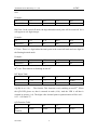
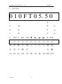
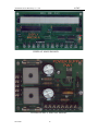
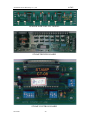
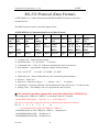
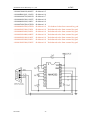
ACME ACME Electronic Machinery Co., Ltd. ACME 700 Series Bench Type User Manual ACME Electronic Machinery Co., Ltd. NO.40 Hwan-Gong Road Yung-Kang City, Tainan County, 71041 Taiwan TEL: 886-6-2333121 FAX:886-6-2329362 E-Mail: [email protected] Web: www.acmeelmc.com.tw Any company, product or service names found in this document may be the trademark or registered trademarks of their respective companies. 2012/6/20 1 ACME ACME Electronic Machinery Co., Ltd. TABLE OF COTENTS 1、Design Principle ................................................................................................ 4 2、Control and Switches ......................................................................................... 4 1) Machine Body.............................................................................................. 4 1. Power Switch ....................................................................................... 4 2. Motor Switch ....................................................................................... 4 3. Light Switch ......................................................................................... 4 4. Cancel Button....................................................................................... 4 2) Control Box ................................................................................................. 4 ※12 Function Key....................................................................................... 5 1.Unit ....................................................................................................... 5 2.Set ......................................................................................................... 5 3.Mode ..................................................................................................... 5 4.R/F......................................................................................................... 5 5.Q/D........................................................................................................ 6 6. ........................................................................................................... 7 7. ........................................................................................................... 7 8. .......................................................................................................... 7 9. .......................................................................................................... 7 10.Enter .................................................................................................... 7 11.RST ..................................................................................................... 7 12.Format ................................................................................................. 7 ※3 Condition LED ...................................................................................... 8 1.Err LED................................................................................................. 8 2.Q/D LED ............................................................................................... 8 3.R/F LED ................................................................................................ 8 3) Calculator..................................................................................................... 8 ※Function key............................................................................................. 8 1.Off ......................................................................................................... 8 2.On .......................................................................................................... 8 3.Print ....................................................................................................... 8 4.Item + ................................................................................................. 8 5.Item +/- ............................................................................................ 8 ※Decimal modes selector ........................................................................... 8 1.F ............................................................................................................ 8 2.CUT....................................................................................................... 8 2012/6/20 2 ACME ACME Electronic Machinery Co., Ltd. 3.UP ......................................................................................................... 9 4.5/4 ......................................................................................................... 9 4) Air Combination (Conveyer Type Only)................................................... 9 3、Operation ........................................................................................................... 9 4、Maintenance .................................................................................................... 10 1) P.C. Tube ................................................................................................... 10 2) Conveyer Belt ............................................................................................ 10 3)Debris & Chips ........................................................................................ 10 4) Light bulbs ................................................................................................. 10 5) Calculator................................................................................................... 10 5、Troubleshooting ............................................................................................... 11 ※Measuring Machine ............................................................................... 11 ※Calculator ............................................................................................... 11 ◎Supplement ........................................................................................................ 13 A、Installation........................................................................................... 13 B、Spare Parts ........................................................................................... 14 C、Control Box ......................................................................................... 15 D、Schematic ............................................................................................ 16 E、Parts Index ........................................................................................... 21 F、RS232 Protocol .................................................................................... 22 2012/6/20 3 ACME ACME Electronic Machinery Co., Ltd. 1、Design principle ACME electronic measuring machines are operated by photo electronic circuitry. A small incandescent light bulb and a phototransistor are aligned face to face in a vertical configuration to create a basic sensor unit. These sensor units are then made horizontally in line at one-inch interval. Eight of these sensor units and a CD-4021 shift register installed in one circuit board become a segment of the bridge. When the leather passes through these sensor bridges, the leather blocked out the light emitted from the incandescent light bulbs. Thus, the terminal voltage of each light- obstructed phototransistor rises. Then the number of sensor is blocked represent the width of the leather. In the way, leather carry through the sensors by conveyers. The movement generated the length signal. The photo sensors incorporate with parallel input and serial output register. The CD4021 will function as following: Once the conveyer signal occurring, the conveyer signal extrudes the ball inside the slot out for count. As the end of the leather pass over the sensor, the conveyer signal will extrude no ball for count. The change state from having a ball to none of ball in the extrusion will initial a command for display the total amount of ball, and print out, etc. 2、Control and switches 1) Machine Body 1.Power switch: For master control of power. 2.Motor switch: For moving and stopping of conveyers. 3.Light switch: Control the on/off of the incandescent light bulbs. Note: Machine will not work if this switch was turned off. 4.Cancel button: Push this button before the hide completely passes through the sensor bridges will cancel this particular measurement. 2012/6/20 4 ACME ACME Electronic Machinery Co., Ltd. 2)Control Box(See Supplement C-Control Box) ※12 Function Key 2 2 2 1.Unit--To change measuring unit by IN(inch )、DM (decimeter )、FT (feet )、M 2 2 (meter ). 2.Set--To set the percentage of compensation and the number of batch set. CMPST % ==>Compensation. To recover the loss in the measuring, the fair compensation is needed. BCHST==>Batch set. For the advantage to package, the number of BCHST is adjustable. Note: The data that set previously will be reserved till the “Format Button” is pushed. 3.Mode--For display batch total and grand total. BTT (Batch Total)==>The total number of batches. And these batches must be measured in the same unit. GTT (Grand Total)==>The total area that measured in one batch. Note:When the unit is changed (ex. IN==>DM or FT==>IN), the total number will be clear, and count again from 0. 4.R/F (Round off/Four Digits): For decide the calculation. Round Off==>Value are rounded off (0、1、2、3、4 cut off;5、6、7、8、9 are round up). Four==>In this case, the display will show the value with four digits. According to the different unit, the digits will be different, too. IN Case: In round off mode, the value will be round off, so the last digit will always be 2012/6/20 5 ACME ACME Electronic Machinery Co., Ltd. zero. Example: Fix 1713 1184 1125 1999 Round Off 1710 1180 1130 2000 DM Case: In the round off mode, the digit behind decimal point will be round off. So it will appear as a 4 digits integer. Example: Fix 075.3 111.4 046.5 999.9 Round Off 0075 0111 0047 1000 FT Case: There is 1 digit behind decimal point in the round off mode and two digits in the floating decimal mode. Example: Fix 05.01 08.50 10.19 09.99 Round Off 05.0 08.5 10.2 10.0 2 M Case: This function is disabling in unit M 2 . R/F Digits Table R F 2 IN DM FT M 0 . Disable . . . 2 5.Q/D(1/4 or 1/10)--The fraction. This function is only enabling at unit FT . When the Q/D LED glows on, that is counted in tenth (1/10). And the LED is off that is counted in quarter (1/4). The digits after decimal point in quarterization will be 0.00、 0.25、0.50 and 0.75. Q/D Function Table Q/D Function 2012/6/20 2 IN DM FT M Disable Disable Enable Disable 6 ACME ACME Electronic Machinery Co., Ltd. Example: D/F 05.09 05.10 05.11 05.14 05.15 D/R 05.1 05.1 05.1 05.1 05.2 Q/F 05.00 05.25 05.25 05.25 05.25 Q/R 05.2 05.2 05.2 05.2 05.2 D/F 05.24 05.25 05.34 05.35 05.40 D/R 05.2 05.3 05.3 05.4 05.4 Q/F 05.25 05.25 05.25 05.25 05.50 Q/R 05.2 05.2 05.2 05.5 05.5 D/F 05.64 05.65 05.94 05.95 06.00 D/R 05.6 05.7 05.9 06.0 06.0 Q/F 05.5 05.5 5.75 5.75 06.00 Q/R 05.5 05.7 D/F:1/10 and Four Digits D/R:1/10 and Round Off Q/F:1/4 and Four Digits Q/R:1/4 and Round Off 05.7 06.0 06.0 6.--Increase number. 7.--Decrease number. 8.--Move cursor rightward. 9.--Move cursor leftward. Note: 6)~~9) are used in adjustment in BCHST and CMPST. 10.Enter--When the number of BCHST or CMPST was adjusted, it is necessary to push “Enter Button” to input the number. If never do this action, the predetermination setup will lost. 11.RST--Clear the data of BTT and GTT. 12.Format--Clear all the data of BTT、GTT、CMPST and BCHST。 2012/6/20 7 ACME ACME Electronic Machinery Co., Ltd. ※3 Condition LED 1.Err LED(Error LED)--This LED glow on express the measuring is occurred any error. Please reset the power. 2.Q/D LED(1/4 or 1/10 LED)--For 1/4 or 1/10 increment in last digit. This LED glow on express it is 1/10 increment. 3.R/F LED(Round Off/Four Digits LED)--This LED glow on express the value will display by four digits. And in the round off case, when the last digit is 0,1,2,3 or 4, the last digit will be cut off. In the other hand, when the last digit is 5,6,7,8 or 9, the last digit will be change to zero and add 1 to the 2nd last digit. 3) Calculator ※Function Key 1.Off--Power is off. 2.On--Power is on, but no printing is performed. 3.Print--Power is on and printer is operational. 4.Item +--Power is on and printer is operational. The total number of items added and subtracted is printed along with the result when you press the ◊/# or * key. Note: Please choose this item when you are measuring. 5.Item +/−--Power is on and printer is operational. The total number of items added less the total number of items subtracted is printed along with the result when you press the ◊/# and *. ※Decimal modes selector 1.F--Floating decimal. 2.CUT--Values are cut off to the number of decimal places specified by the current Decimal Place Selector setting. 2012/6/20 8 ACME ACME Electronic Machinery Co., Ltd. 3.UP--Values are rounded up to the number of decimal places specified by the current Decimal Place Selector setting. 4.5/4--Values are round off (0, 1, 2, 3, 4 are cut off; 5, 6, 7, 8, 9 are rounded up) to the number of decimal places specified by the current Decimal Place Selector setting. 4) Air Combination (Conveyer Type Only) 1.Filter--Turn the drain for drainage weekly. 2.Regulator--Keep the pressure at 4~5 Kg. 3.Lubricator--Keep the lubricant enough. It is necessary to check and fill weekly. 4.FRL System--This system control the sliding of words plate. Keep the pressure among 0.8Kg~1.0Kg. 3、Operation 1) The multifunction of the sensor is unpredictable. To prevent the machine‘s trouble that cause by incorrect measuring, test sheet should be use to check the proper function of the machine before the measurement work starting and in the end of every measuring run. 2) The batch number is subject to the number of piece to be in a batch, which will be set by operator. The batch number that we set will count down after every measurement. When the piece remains only one, the buzzer will buzz. 3) The compensation is to correct the operational error. The percentage of compensation basically depends on the operation of measuring. The factors included softness of leather and measuring skill. Calculate the different measuring result between skill and non-skill of operator, or carefully measuring and easy pass through, is a reference of compensation to be set. 4) Operator put the leather on the feeding table and sends the leather pass through the sensor bridge. To get the maximum area, it is necessary to flatten the leather. Press leather with proper strength and flatten it is used to be. If the strength of machine that pull leather is too strong to let us press the leather, the operator should adjust the 2012/6/20 9 ACME ACME Electronic Machinery Co., Ltd. machine‘s pulling strength by turning clutch nut. Never pull the leather against machine; it will make measurement error that caused by slide. 4、Maintenance 1) P.C. Tube Clean this P.C. Tube periodically by using only copper/brass polish on non-abrasive clean agent. It is important to keep this tube from accident scratches. Note: Do not use acetone, thinner or solvent base solutions to clean this tube. 2) Conveyer Belt Inspect each green conveyer belt to make sure it is properly on track. Make sure there is no foreign object adheres to the belt. 3)Debris & Chips Lift the front cover and the P.C. tube assembly. Use compressed air and lightly blow down the aluminum casing of the incandescent light bulbs. 4) Light bulbs Lifting the front cover and the P.C. tube assembly for brush the light bulbs to sweep dust out. If there is any defect, please locate the defective one and unplug. Insert a new light bulb back in position. 5) Calculator It is necessary to cover a wrap to protect the keyboard from dust. When you replace another model calculator, you have to replace a parallel interface, too. When the ink ribbon exhausted, please change a new one. Do not add ink into the ribbon. This action will destroy the circuit and mechanism of the calculator. 2012/6/20 10 ACME ACME Electronic Machinery Co., Ltd. 5、Troubleshooting ※Measuring Machine Pro 1--No Read Out Cause: Power is off Solution: Turn on power. Cause: Encoder driver Belt drop out Solution: Open the front cover to check the encoder driver belt whether on the right position or not. If not, put the belt on the right position. Cause: Control Box does not connect with Machine. Solution: Check the connector does connect correctly. Pro 2--0000 Readout Cause: There is any spot on the P.C. Tube. Solution: Clean the P.C. Tubes by using only copper/brass polish on non-abrasive clean agent. It is important to keep the tube clean and lucent. Pro 3--Power switch is on, but machine does not work. Cause: Breaker was turn off. Solution: Turn on the breaker. ※Calculator Pro 1--Can not print. Solution: Check the connector does connect correctly. Solution: Check the selector does put in the right position. Pro 2--The number of calculator printed different from control box appear.(Ex: The control box display 47.5, but Calculator prints 4.5. the 7 was lost) Cause: Interface is breakdown. Solution: Call for fixing, or purchase a new interface. 2012/6/20 11 ACME ACME Electronic Machinery Co., Ltd. Pro 3--Push the numeric key, but it does not work. Solution: Send the calculator back to factory for fixing. 2012/6/20 12 ACME ACME Electronic Machinery Co., Ltd. SUPPLEMENT A、Installation 1) Supporting legs Acme’s bench type measuring machine comes with for supporting legs. For the ease and safety of the installation screw, please use a forklift or similar equipment to elevate the machine slightly higher than the vertical height of the legs. Each of these supporting legs is properly marred and corresponded to angle steel located at four base corners of the machine. Connect each leg with its respective angle steel by using the hexagonal bolts and nuts, round and spring washers. Make sure each leg and the angle steel are securely tighten before lowering the machine and withdraw the for lift equipment. 2) Display Box Unpack the Display Box from its original carton. Locate the opening on the left side of the rot table front cover. Flip the front cover until it rests on top of two cylindrical rubber stoppers, which can be found on the back of the machine. Then connect connectors together. 3) Calculator (Adding Machine) Locate the left compartment directly underneath the Display Box Section. Unlatch the cover and find the 15 Pin Calculator female D-Type into the opening located on the bottom of the compartment. Unpack the Calculator from its carton. Find the 15-pin Calculator male connector and connect both. 4) Feeding Table Install and fasten the Feeding Table onto the steel beam with pre-drilled holes. A Green ground wire can be found on the underside of the Feeding Table. Secure this ground wire with the steel beam also. 5) Back Plate Position of the Back Plate can be changed depending on customer‘s measuring preference. For a through-feed measuring (two operators), lock the back plate into the horizontal position. For return-feed (One operator), keep the back plate in the vertical position. 2012/6/20 13 ACME ACME Electronic Machinery Co., Ltd. Note: When the Back Plate is at the through-feed position, compartment covers cannot be removed. 6) Power Cord Depending on the local electrical voltage rating, a plug will be supplied with the machine. However, if the supplied plug is not suitable with the local socket specification, please make the change under the supervision of a certified electrician. If the local voltage supply is not stable or fluctuate frequently, a voltage regulator should be installed and used concurrently with the measuring machine. B、Spare parts 1 Cover、 1 Manual、 20 Bulbs、 10 Sensors、 1 Test Sheet、 6 Fuse。 2012/6/20 14 ACME ACME Electronic Machinery Co., Ltd. C、Control Box 0 1 0 F T 0 5. 5 0 E U M N Err N O T Q/D I D E R/F T SET E R/F Q/D ↑ ↓ ◎ ◎ ◎ ◎ ◎ ◎ 單 設 顯 位 進 上 位 定 示 數 位 → ← R RST ◎ ◎ ◎ ◎ ◎ 下 右 左 確 跳 定 離 (1) (2) (3) (4) (5) (6) (7) (8) (9) (10) (11) 2012/6/20 15 ACME ACME Electronic Machinery Co., Ltd. 2012/6/20 16 ACME ACME Electronic Machinery Co., Ltd. 2012/6/20 17 ACME ACME Electronic Machinery Co., Ltd. FOR 700B-C STANDARD MODEL FOR 700B-R & 700B-P MODEL 2012/6/20 18 ACME ACME Electronic Machinery Co., Ltd. DISPLAY MAIN BOARD POWER SUPPLY FOR ALL MODEL 2012/6/20 19 ACME ACME Electronic Machinery Co., Ltd. SENSOR BAR FOR ALL MODEL STAMP DRIVER BOARD STAMP CONTROL BOARD 2012/6/20 20 ACME ACME Electronic Machinery Co., Ltd. ACME 700 SERIAL BENCH TYPE MEASURING MACHUNE PARTS INDEX 2 1 ACME Elecronic 34 42 43 35 4 39 38 45-55 5 31 6 7 32 10 33 41 36 28 37 30 9 8 11 27 19 40 3 20 14 44 56 24 29 26 21 PW1 25 18 23 22 57 Part Description No. Part Description No. Part Description No. 1 PCB Display MMD 96-A 20 Switch, Master Power 39 End Bearing Plate 2 PCB Counter MMC 03-A 21 Switch, Motor 40 Return Sheet 3 PCB Calculator Driver PTDR-5A 22 Circuit Breaker 5A 41 Feeding Table 4 PCB Sensor SN91B 23 AC Filter 42 Switch, Cancel 5 Phototransistor 24 Bearing Pillow B 43 Buzzer 6 Supporter 25 Bearing Pillow A 44 Switch, Lamp 7 Encoder Assembly 26 Clutch Spring Loading 45 Unit 8 Transformer 5V. Lamp 27 Belt Conveyer 10x760mm 46 Set 9 Transformer 10V. 22V 28 Belt M-37 Inch 47 Mode 10 Lamp Bulbs 29 Belt K-31 Inch 48 R/F 11 N/A 30 Belt K-26 Inch 49 Q/D 12 N/A 31 Belt Encoder Driver 50 Up 13 N/A 32 Blade 51 Down 14 Relay 24V 33 Roller Shouldering 52 Right 15 N/A 34 Roller Bushing 53 Left 16 N/A 35 P.C. Tube 54 Enter 17 N/A 36 Back Plate 55 Rest 18 PCB Power PW1 37 Pivot Back Plate 19 Motor 1/4 HP.4P 38 Axial Sensor 2012/6/20 21 ACME ACME Electronic Machinery Co., Ltd. RS-232 Protocol (Data Format) ACME MMC10-A Leather Measurement Module has RS232 function to interface external devices. The RS232 protocol can be seen in the figure below.: ACME MMC10-A Communication Protocol (Data Format) 1 2 3 4 5 6 Leading Returned Command Item Unit Code Value Code Number “~” “0” or ASCII “1” ASCII 1 Byte 1 Byte * * * * “10” ASCII XXXX ASCII (HEX) 2 Bytes 7 Deducted Reserve Real Area Area XX XXXX ASCII ASCII (BCD) 4 Bytes 2 Bytes 4 Bytes 9 10 Check Sum Ending Code X ,XXXX XX 0Ah+0Dh ASCII ASCII ASCII Hexadecimal (BCD) (HEX) (HEX) 1 Byte 5 Bytes 2 Bytes 2 Bytes Leading Code:Start of encapsulation。 Returned Value:”0” Correct,”1” Error。 Command Code:Code “10” indicate to transmit the result of measured。 Item Number:represent the sequence number of the measured。 2 * Unit:00 FT ,01 IN,02 DM,03 M * * * * * 8 2 。 Deducted Area:4 bytes deducted area (Use external key pad to deduct)。 Reserve:Future use。 Real Area:Real Area (5bytes:”,” + 4bytes)。the ”,” is a splitter。 Check Sum:Exclusive-OR Sum from Returned Code to Real Area。Can do not care。 Ending Code:The Ending Code is to represent the end of record。 ※ The measure machine output data using fixed baud rate (19200,8,N,1). The ending code “CHR(10)+ CHR(13)” is not show on the PC Terminal. ~01000100005500,05602F 05.60 – 0.1 = 05.50 deducts 0.1 The above record can be split and reference Communication Protocol as follow: EX: 1 2 3 4 5 6 7 8 9 10 ~,0,10,0010,00,0550,0,,0560,2F,CHR(10)+ CHR(13) ~010000F0010901,111053 CHR(10)+ CHR(13) deducts 0.2 ~010000E0008800,091050 deducts 0.3 ~010000D0009300,09705D deducts 0.4 2012/6/20 22 ACME ACME Electronic Machinery Co., Ltd. ~010000C0008300,088055 ~010000B0012001,126058 ~010000A0007500,082054 ~01000090009300,10102E ~01000080009100,10002C ~01000070008700,09702B ~01000060004700,04702B ~01000050003200,032028 ~01000040002600,026029 ~01000030004400,04402E ~01000020001800,01802F ~01000010002900,02902C ~01000120002200,02202E 2012/6/20 deducts 0.5 deducts 0.6 deducts 0.7 deducts 0.8 deducts 0.9 deducts 1.0 deducts 0.0 deducts 0.0 deducts 0.0 deducts 0.0 deducts 0.0 deducts 0.0 deducts 0.0 23 No deducted value from external key pad No deducted value from external key pad No deducted value from external key pad No deducted value from external key pad No deducted value from external key pad No deducted value from external key pad No deducted value from external key pad