1
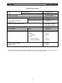
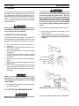
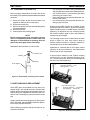
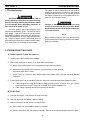
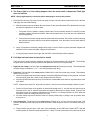
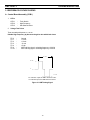
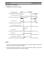
PCM-875 PLASMA CUTTING CONSOLE/POWER SOURCES with CE Compliances 230 V, 50 Hz, 3-Phase 400 V, 50 Hz, 3-Phase Service Manual 558000-892 0202 WARNING ARC WELDING AND CUTTING CAN BE INJURIOUS TO YOURSELF AND OTHERS. TAKE PRECAUTIONS WHEN WELDING. ASK FOR YOUR EMPLOYER’S SAFETY PRACTICES WHICH SHOULD BE BASED ON MANUFACTURERS’ HAZARD DATA. ELECTRIC SHOCK - Can kill l Install and earth the welding unit in accordance with applicable standards. l Do not touch live electrical parts or electrodes with bare skin, wet gloves or wet clothing. l Insulate yourself from earth and the workpiece. l Ensure your working stance is safe. FUMES AND GASES - Can be dangerous to health l Keep your head out of the fumes l Use ventilation, extraction at the arc, or both, to keep fumes and gases from your breathing zone and the general area. ARC RAYS - Can injure eyes and burn skin. l Protect your eyes and body. Use the correct welding screen and filter lens and wear protective clothing. l Protect bystanders with suitable screens or curtains. FIRE HAZARD l Sparks (spatter) can cause fire. Make sure therefore that there are no inflammable materials nearby. NOISE - Excessive noise can damage hearing l Protect your ears. Use ear defenders or other hearing protection l Warn bystanders of the risk. MALFUNCTION - Call for expert assistance in the event of malfunction. READ AND UNDERSTAND THE INSTRUCTION MANUAL BEFORE INSTALLING OR OPERATING. PROTECT YOURSELF AND OTHERS! TABLE OF CONTENTS SECTION 1 SECTION 2 SECTION 3 SECTION 4 SPECIFICATIONS ............................................................................................................ 3 MAINTENANCE ................................................................................................................ 4 General, Inspection and Cleaning, PT-27 Torch Consumable Parts, Flow Switch, IGBT Handling & Replacement TROUBLESHOOTING ...................................................................................................... 6 Troubleshooting, Troubleshooting Guide, Reference Voltage Checks, Sequence of Operation, Schematic and Wiring Diagrams REPLACEMENT PARTS ................................................................................................ 19 Maintenance and Repair work should be performed by an experienced person, and electrical work only by a trained electrician. Do not permit untrained persons to inspect, clean, or repair equipment. Use only recommended replacement parts. For installation and operation instructions, see 558000-880 (F-15-418). 2 SECTION 1 SPECIFICATIONS PCM-875 Specifications Rated 60% Duty Cycle* 60 A @ 120 V dc Output 100% Duty Cycle* 50 A @ 120 V dc Output Current Range 10 to 60 Amperes Open Circuit Voltage 275 V dc Rated Primary Input 220 V ac, 50/60 Hz, 3-phase 24 A/phase @ 7.2 kW Max. Output Power 400 V ac, 50/60 Hz, 3-phase 13 A/phase 60 A @ 120 Vdc Power Factor @ 60 Amperes Output 90% (220 V, 3-phase) 92% (400 V, 3-phase) Efficiency @ 60 Amperes Output 90% Typical Current Capacity PT-27 80 A DCSP Air Requirements PT-27 150 l/min @ 4.5 - 5.2 bar Dimensions Length 516 mm Height 409 mm w/handles 465 mm Width w/o opt. storage 275 mm w/opt. torch storage 333 mm Weight of PCM-875 System 39.5 kg Shipping Weight 45.4 kg * Duty cycle is based on a 10-minute period; therefore, a 60-percent duty cycle means the power source may operate for 6 minutes with a cool down period of 4 minutes and a 100-percent duty cycle means the power source may operate continuously. 3 SECTION 2 MAINTENANCE 2.1 GENERAL If this equipment does not operate properly, stop work immediately and investigate the cause of the malfunction. Maintenance work must be performed by an experienced person, and electrical work by a trained electrician. Do not permit untrained persons to inspect, clean, or repair this equipment. Use only recommended replacement parts. The PT-27 torch head contains a gas flow check valve that acts in conjunction with the flow switch and circuitry within the power source. This system prevents the torch from being energized with high voltage if the torch switch is accidentally closed when the shield is removed. Always replace torch with the proper torch manufactured by ESAB since it alone contains ESAB¹s patented safety interlock. Be sure that the wall disconnect switch or wall circuit breaker is open before attempting any inspection or work inside of the PCM-875. To assemble the consumable parts, refer to Figure 2-1. A. Place nozzle, swirl baffle and electrode into the shield as shown. B. Thread assembly to the torch body and hand tighten. Always make sure the shield is very tight before cutting. 2.2 INSPECTION AND CLEANING Frequent inspection and cleaning of the PCM-875 is recommended for safety and proper operation. Some suggestions for inspecting and cleaning are as follows: A. Check work cable for secured connection to workpiece. B. Check safety earth ground at workpiece and at power source chassis. C. Check heat shield on torch. It should be replaced if damaged. D. Check the torch electrode and cutting nozzle for wear on a daily basis. Remove spatter or replace if necessary. E. Make sure cable and hoses are not damaged or kinked. F. Make sure all plugs, fittings, and ground connections are tight. G. With all input power disconnected, and wearing proper eye and face protection, blow out the inside of the PCM-875 using low-pressure dry compressed air. ELECTRODE SWIRL BAFFLE NOZZLE SHIELD Water or oil occasionally accumulates in compressed air lines. Be sure to direct the first blast of air away from the equipment to avoid damage to the PCM-875. H. Occasionally, bleed all water from the filter beneath the air filter-regulator. IMPORTANT! MAKE SHIELD VERY TIGHT! 2.3 PT-27 TORCH CONSUMABLE PARTS Figure 2-1. Assembly of PT-27 Torch Front End Parts Make sure power switch on PCM-875 is in OFF position before working on the torch. 4 SECTION 2 MAINTENANCE 2.4 FLOW SWITCH (FIGURE 2-2) • When excessive contamination is found in the air, the flow switch (FS-4) should be disassembled and cleaned as follows: • A. Ensure the system is shut down and there is no trapped air under pressure in the piping. B. Remove the piston plug. C. Remove the spring. Use care when handling spring to prevent distortion. D. Remove the piston. E. Clean all parts with cleaning agent. • • Use grounded work station with grounded floors and grounded wrist straps when handling devices. Use a 100W resistor in series with the gate when performing curve tracer tests. Never install devices into systems with power connected to the system. Use soldering irons with grounded tips when soldering to gate terminals. When mounting IGBT modules on a heatsink, certain precautions should be taken to prevent any damage against a sudden torque. If a sudden torque (“one-sided tightening”) is applied at only one mounting terminal the ceramic insulation plate or silicon chip inside the module may get damaged. NOTE Ensure cleaning agent does not contain solvents which can degrade polysulfone. Warm water and detergent is recommended for cleaning. Allow all parts to dry thoroughly before reassembly. The mounting screws are to be fastened in the order shown in Figure 2-3. Also, care must be taken to achieve maximum contact (i.e. minimum contact thermal resistance) for the best heat dissipation. Reassemble the flow switch in reverse order. Application of a thermal pad on the contact surface improves its thermal conductivity. See Replacement Parts section for the required pad. PISTON PLUG A torque wrench should be used. Tighten mounting screws to 32 kg-cm; wire connecting screws to 22 kgcm. If torque is too heavy, the device can damage like the above “one-sided tightening”. SPRING PISTON FLOW SWITCH Two-Point Mounting Type Temporary tightening è Final tightening è Figure 2-2. Disassembly / Assembly of Flow Switch 2.5 IGBT HANDLING & REPLACEMENT Since IGBT gates are insulated from any other conducting region, care should be taken to prevent static build up, which could possibly damage gate oxides. All IGBT modules are shipped from the factory with conductive foam contacting the gate and emmiter sense pins. Four-Point Mounting Type Temporary tightening èèè Final tightening èèè Always ground parts touching gate pins during installation. In general, standard ESD precautlions application to FETs should be followed. Other handling precautions that should also be observed are as follows: Figure 2-3. Screw Fastening Order 5 SECTION 3 TROUBLESHOOTING 3.1Troubleshooting The cause of control malfunctions can be found by referring to the sequence of operations and electrical schematic diagram (Figure 3-1 or 3-3) and checking the various components. A volt-ohmmeter will be necessary for some of these checks. ELECTRIC SHOCK CAN KILL! Be sure that all primary power to the machine has been externally disconnected. Open the line (wall) disconnect switch or circuit breaker before attempting inspection or work inside of the power source. Voltages in plasma cutting equipment are high enough to cause serious injury or possibly death. Be particularly careful around equipment when the covers are removed. Check the problem against the symptoms in the following troubleshooting guide. The remedy may be quite simple. If the cause cannot be quickly located, shut off the input power, open up the unit, and perform a simple visual inspection of all the components and wiring. Check for secure terminal connections, loose or burned wiring or components, bulged or leaking capacitors, or any other sign of damage or discoloration. NOTE Before checking voltages in the circuit, disconnect the power from the high frequency generator to avoid damaging your voltmeter. 3.2TROUBLESHOOTING GUIDE A. Power Light (PL1) does not come on. 1. Visually inspect the machine for any damage. 2. Check if the cooling fan is running. If not, then check the following : a. Check if the machine power cord is plugged to the input power receptacle. b. Measure the input power at the receptacle. If not present, then check the wall disconnect switch and it’s fuses. c. Check Fuse (F1). If fuse is ok, then check the input circuit breaker (CB1) for proper operation. Replace if defective. 3. If above items check OK , the problem is internal. Send unit to an Authorized Repair Station for repair. a. If the cooling fan is running, then measure voltage between pins P2-11 and P2-14 of the control board (should be 115 VAC). If there is no voltage, then replace transformer T2. b. If the voltage is present, then the pilot light may be defective. B. No Air Flow A. Check air inlet supply. Unit requires 150 l/min at 4.5 bars. B. Check air hose and connections. Tighten if leaking. C. Does air flow when “air test” switch is in test position? a. If not, check torch consumables, replace if necessary. b. If above items check OK , the problem is internal. Take unit to an Authorized Repair Station for repair. 6 SECTION 3 TROUBLESHOOTING C. The Power light is on, but nothing happens when the torch switch is depressed. Fault light does not activate. NOTE: Unplug high frequency connection before attempting to work on this problem. 1. Check the Pilot Arc fuse (F2) located on the rear panel. An open fuse will indicate a short in the torch. If the fuse is all right, then check the following: a. With the machine power on, depress the torch switch. On the control board the LED 1 should be lit as long as the switch is depressed. If not then check: i. Turn power off to the machine. Unplug Control board. Put an ohmmeter across P5-1 and P5-2 to take resistance reading. Depress torch switch. Meter should read a short. If not, then one of the following is not working properly: ii. Torch switch or the leads. Unplug the torch switch leads at the machine. Put a meter across the two plug pins. Should read a short when the torch switch is depressed. If not, then either broken switch leads or defective switch. b. Check T2 transformer secondary voltages at the plugs P1 and P2. Refer to system schematic. Replace the transformer if the correct secondary voltages are not present. c. If everything above checks out all right, then the PCB1 Control Board should be replaced. D. Fault light activates when torch switch is closed. The Fault circuit is used to monitor conditions necessary for the safe operation of the PCM-875. The fault light will glow amber under the following conditions and operations will come to a complete stop: 1. High/Low line voltage. The Fault Light will rapidly blink on and off (5 times per second). This indicates that the input voltage is outside the “+” or “-” 15% safe operating range rating. 2. Flow fault - The fault light will be mostly on but will blink off for 1/10th of a second every second. This indicates that the air flow is low. a. Check the air pressure at the machine regulator. It should be adjusted to 65 psig. If no air pressure, check the air at the supply point. Also, check for any obstructions in the air hose. b. Air flow may be blocked at the torch tip. Check the torch consumables. Also check for any obstructions in the torch leads. NOTE: If above items check OK , the problem is internal. send unit to an Authorized Repair Station for repair. c.. Put the ‘Air Check’ switch to On position. Air should flow through torch. If not, then the flow switch may be stuck due to oil in the air. Clean air flow switch per supplier’s instructions or replace switch. To check if the flow switch is open, put voltmeter leads between P1-12 and P1-1. It should read about 12 VDC. When the flow switch closes, the voltage will drop to zero volts. d. Air Check switch may also be defective if the air is flowing continuously or putting in the On position does not turn air on. 3. Over Temperature. The fault light will be mostly off but will blink on for 1/10 of a second, every second. This generally indicates that the duty cycle has been exceeded. Allow the power source to cool before returning to operate. a. Thermal switch may be open. It will open if the temperature at the IGBT base reaches 94oC. With the machine power off, check the continuity between P1-1 and P1-2 of the control board. If the switch is OK, then 7 SECTION 3 TROUBLESHOOTING the ohmmeter should read a direct short. If not then it should read open. b. If the switch is defective, replace it. Clean the surface of the heat sink before installing the switch. 4. Over Current. The fault light will be on continuously. This indicates that the input current to the main transformer has exceeded preset limits. a. To check if the output is shorted, measure the resistance by putting the ohmmeter leads (make sure to disconnect HI Frequency leads):”+” of the meter to Torch “+” output terminal and Work “-” lead of the meter to the “-” output terminal. Reading should be about 2 K Ohms. Reverse the voltmeter leads, the resistance reading should be less than 1.5 K Ohms. b. If the resistance reading is different than above, check the torch, the output bridge and Filter Board (PCB-5). E. Air is On but nothing happens when torch switch is operated. 1. Check the pilot arc fuse located on the rear panel. If it is open, nothing will happen when the torch switch is depressed. 2. Check the torch. Make sure the heat shield is tight. PT27 torch has a built in safety circuit in which the torch will not fire if heat shield is tightly secured. 3. Check to assure high frequency is present at the torch. If not, then listen for high frequency at the high frequency generator. It is located on the bottom/right side of the unit. The high frequency gap is set between 0.71 to 0.78mm Disconnect HI FREQUENCY leads. Check for 115 volt supply to the high frequency unit between P2-12 & P213 of the control board with torch switch closed. 4. With HI FREQUENCY leads disconnected, measure open circuit voltage. It should be 275 VDC between “Work” and “Torch” terminals. If it is not present then any one of the following may not be working properly: a. Check the operation of the Thermal Switch. See D.3.a. above. b. Check Air Check switch operation. It might be stuck in On position. Pilot arc will not initiate if this switch is on the ON position. (safety reasons) c. Check air flow switch. There may be internal short. See D.2.c above. d. Measure voltage across C1 or C2 capacitor. It should be as follows: approx. 325 VDC for the 220 volt unit. approx. 280 VDC to 325 VDC for the 400 volt unit If not, one of following could be defective: 1). Check the capacitors C1 and C2 for any damage. 2.) Check input bridge/SCR Module (IBR) This can be checked without taking it out of the circuit using an volt/ohmeter. Replace it if found defective. Follow bridge installation instructions. 3.) Check Inrush current resistor, R10 and SCR1. Both are located on the input bridge heat sink. Replace it if defective. e. IGBTs (2 on 220 V, and 1 on the 400 V units) may be blown. See IGBT installation procedure. Before replacing IGBTs, make sure to check the zener diodes and pico fuses on the IGBT driver boards. 8 SECTION 3 TROUBLESHOOTING F. High Frequency and Pilot Arc are on but Main Arc does not transfer. 1. Make sure work clamp is connected to work material. 2. Check the torch. Replace consumables if necessary. 3. Make sure the current setting potentiometer is set above 10 amps. If it is, set below 10 amps, then HI FREQUENCY will go on and off at 5 sec intervals. G. Poor Cutting Performance. 1. Check air supply regulator . It should be adjusted to 4.5-5.2 bar. 2. The air supplied to the torch should be free of oil and water. 3. Make sure the consumables in the torch are acceptable. 4. Check open circuit voltage. See E.4 above. 5. Check the output. Use a calibrated current probe capable of measuring 100 amps in the presence of high frequency. H. Air does not shut off. 1. Check air test, the gas solenoid valve is energized when the switch is in the “on” position. 2. Does air flow stop when the torch switch is unplugged? If yes, check and repair the torch. If not, send unit to an Authorized Repair Station for repair. a. Check voltage to solenoid coil, if present when torch switch is unplugged, replace PCB1. If voltage is “0”, replace solenoid valve. I. Main arc is difficult to start. 1. 2. 3. 4. 5. The most common reason is worn or missing consumables. Check and replace if necessary. Input air must be clean and dry. Input air pressure must be between 4.5 and 5.2 bar. Torch connections must be tight. Work cable and clamp must be in good condition and must make a good electrical connection to the material to be cut. 6. If above items check OK , the problem is internal. send unit to an Authorized Repair Station for repair. a. Missing or weak pilot arc. Check pilot arc fuse, open circuit voltage, pilot arc resistors and pilot arc wiring. b. Inoperative starter board (PCB-5). 9 SECTION 3 TROUBLESHOOTING 3.3REFERENCE VOLTAGE CHECKS A. Control Board Assembly (PCB1) 1. LED’s LED-1 LED-2 LED-3 2. - Torch Switch High Frequency Gas Solenoid Valve Voltage Test Points Tests are made with power on - no arc. Disable High Frequency by disconnecting blue wire with black sleeve TP-0 TP-1 TP-2 TP-3 TP-4 TP-9 TP-10 - Ground +15 vdc +12 vdc -12 vdc +5 vdc IGBT’s driving signal - switching frequency = 20 KHz IGBT’s driving signal - switching frequency = 20 KHz 50 µsec 13 vdc 0 13 vdc For 220 VAC input, the IGBT off time is 3µsec. For 400 VAC input, the IGBT off time is 6µsec. Figure 3.1 IGBT Gating Signal 10 SECTION 3 TROUBLESHOOTING 3.4 SEQUENCE OF OPERATION A. TRIGGER LOCK “UNLOCK” position TORCH SWITCH PUSH RELEASE OPEN CLOSE GAS SOLENOID VALVE 2 SEC. PREFLOW 10 SEC Postflow FLOW SWITCH CLOSE OPEN FAULT OVERLOAD LIGHT ENERGIZE HF CIRCUIT INVERTER CUTTING ARC (CURRENT) NOTES: 1. When the torch switch is pushed during postflow period, the postflow and preflow times are canceled, and the HF is energized immediately. 2. When the amber fault light comes on, cutting operation should be stopped. The postflow time starts from the moment the torch switch is released. 11 SECTION 3 TROUBLESHOOTING B. TRIGGER LOCK "LOCK" position PUSH RELEASE PUSH RELEASE TORCH SWITCH OPEN CLOSE GAS SOLENOID VALVE 2 SEC. PREFLOW 10 SEC Postflow POSTFLOW CLOSE OPEN FLOW SWITCH FAULT LIGHT ENERGIZE HF CIRCUIT INVERTER CUTTING ARC (CURRENT) NOTES: 1. When the torch switch is pushed during postflow period, the postflow and preflow times are canceled, and the HF is energized immediately. 2. When the red fault light comes on, cutting operation should be stopped. The postflow time starts from the moment the torch switch is released. 3. FAULT light is on during second "turn-off" trigger only. This does not affect performance in any way. 12 13 D-36918 Figure 3.1 - Schematic Diagram, PCM-875, 230 V, 50/60 Hz, 3-Phase 14 D-36917 Figure 3.2 - Wiring Diagram (Sheet 1 of 2), PCM-875, 230 V, 50/60 Hz, 3-Phase 15 D-36917 Figure 3.2 Wiring Diagram (Sheet 2 of 2), PCM-875, 220 V, 50/60 Hz, 3-Phase 16 D-36604 Figure 3.3 - Schematic Diagram, PCM-875, 400 V, 50/60 Hz, 3-Phase 17 D-36605 Figure 3.4 Wiring Diagram (Sheet 1 of 2), PCM-875, 400 V, 50/60 Hz, 3-Phase 18 D-36605 Figure 3.4 - Wiring Diagram (Sheet 2 of 2), PCM-875, 400 V, 50/60 Hz, 3-Phase SECTION 4 REPLACEMENT PARTS 3, 4 5, 4 6 1, 2 7 8, 9 16 15 8 10, 11 14 12 13 Fig. 4-1. PCM-875 Power Source, Front View Item No. Qty. Req. Part No. 1 2 3 4 5 6 7 8 9 10 11 12 13 14 15 16 1 1 1 2 1 1 1 2 1 1 1 4 1 1 1 2 558000373 558000372 558000698 558000596 558000385 558000383 558000384 558000593 558000594 558000178 558000608 558000552 558000630 558000631 558000599 558000598 Circuit Symbol Description KNOB POT. 10K 2W (NOMEX INSUL. - 676876) SWITCH TOGGLE SPST 2 POS 15 A 125 V SWITCH SEAL BLACK SWITCH TOGGLE DPDT 2 POS 15 A 125 V LAMP LED YEL 12 V LAMP NEON WHITE GROMMET RUBBER 1.50 ID x 1.76 OD GAUGE 1.50 160 PSI WHITE STRAIN RELIEF HEYCO #1214 WORK CABLE 25 FT. (Not Shown) FOOT RUBBER CHASSIS PCM-875 DOOR ACCESS YEL (ESAB) LABEL WARNING HI VOLTAGE LABEL ESAB 19 R2 S2 S1 PL2 PL1 SECTION 4 REPLACEMENT PARTS 28 27 25, 26 25, 26 24 29, 30 31 23 32, 33, 34 22 21 35 36 37 38 46 39 40 41 42 43 44, 45 Fig. 4-2. PCM-875 Power Source, Left Side View (230 V) Item No. Qty. Req. Part No. 21 22 23 24 25 26 27 28 29 30 31 32 33 34 35 36 37 38 39 40 41 42 43 44 45 46 1 1 1 1 2 2 2 1 1 1 1 1 1 3 2 2 1 1 1 4 1 2 1 1 1 1 558000626 558000634 558000635 558000636 558000637 558000638 558000639 558000640 558000641 558000642 558000600 558000643 558000622 558000689 558000450 558000400 558000408 558000644 558000412 558000404 558000410 558000532 558000645 558000409 558000625 558000826 Circuit Symbol Description BRIDGE 60ADC 100NS 600 V (PAD - 558000527) CORE SATURABLE STANDOFF INS. BUSBAR NEG CAPACITOR 1800 µf 450VDC GROMMET STRIP PCB ASS'Y 1GBT DRIVER BOARD HOSE AY B/A-2X 1/4NPT RUB 2 FT BUSBAR POS CAPACITOR 1µf 630VDC (Not shown - see wiring) TERM BLOCK 2 POS MODULE INPUT BRIDGE/SCR (PAD - 558000651) CAPACITOR .22µf 1KV (See wiring) METAL OXIDE VARISTOR 275 V (See wiring) IGBT 600 V 100 A (PAD - 558000539) RESISTOR 50 W 10 OHM (PAD - 558000529) CURRENT TRANSFORMER ASS'Y CAPACITOR 40 µf 400 VDC THERMAL SWITCH 194°F RESISTOR 24 W 20 OHMS (PAD 558000528) FLOW SWITCH .25 GPM CAPACITOR 1µf 630W VDC HEATSINK SOL. VALVE 1/4NPT 165 PSI 24 VAC DIODE ZENER 60 V 75 MA (See Wiring) FILTER EMI (230 V CE) 20 D1 L3 TB3 C1, 2 PCB2, 3 C3 TB5 IBR C19 MOV1, 2, 3 Q1, 2 R7, 10 T4 C4 TS1 R3, 4, 5, 6 FS C15, 16 SOL1 ZD1 FN1 SECTION 4 REPLACEMENT PARTS 61 60 59 56, 57, 58 56, 57, 58 62 55 64, 65, 66 54 53 52 51 67 68 69 70 71 72 73 74 75, 76 Fig. 4-3. PCM-875 Power Source, Left Side View (400 V) Item No. Qty. Req. Part No. 51 52 53 54 55 56 57 58 59 60 61 62 64 65 66 67 68 69 70 71 72 73 74 75 76 1 1 1 1 1 2 2 2 1 1 1 1 1 1 3 2 1 1 1 1 4 1 1 1 1 558000626 558000634 558000646 558000635 558000647 558000637 558000638 558000642 558000619 558000649 558000640 558000650 558000643 558000622 558000629 558000400 558000408 558000644 558000654 558000412 558000404 558000410 558000645 558000409 558000625 Circuit Symbol Description BRIDGE 60 ADC 100NS 600 V (PAD - 558000527) CORE SATURABLE MODULE DUAL IGBT 150 A, 1200 V (PAD - 558000526) STANDOFF INS BUSBAR POS CAPACITOR 1800µf 450 VDC GROMMET STRIP CAPACITOR 1µf 630 VDC (See wiring) PCB ASS'Y IGBT DRIVER BOARD CAPACITOR 2µf 800 VDC HOSE ASS'Y B/A x 1/4 NPT RUB BUSBAR NEG MODULE INPUT BRIDGE/SCR (PAD - 558000651) CAPACITOR .22µf 1KV METAL OXIDE VARISTOR 510 V RESISTOR 50W 10 OHM (PAD - 558000529) CURRENT TRANSFORMER ASS'Y CAPACITOR 40µf 400 VDC FILTER EMI (400 V CE) THERMAL SWITCH 194°F RESISTOR 25W 20 OHMS (PAD - 558000528) FLOWSWITCH .25 GPM HEATSINK SOL, VALVE 1/4 NPT 165 PSI 24 VAC DIODE ZENER 60 V 75m A 21 D1 L3 Q1 TB3 C1, 2 C3, 15 PCB2 C16 IBR C19 MOV1, 2, 3 R7, 10 T4 C4 FN1 TS1 R3, 4, 5, 6 FS SOL1 ZD1 SECTION 4 REPLACEMENT PARTS 90, 91 89 88 86 87 85 82, 83, 84 92 81 93 80 94 95 101, 102, 103 96 97 104 98, 99 100 Fig. 4-4. PCM-875 Power Source, Right Side View (230 V) Item No. Qty. Req. Part No. 80 81 82 83 84 85 86 87 88 89 90 91 92 93 94 95 96 97 98 99 100 101 102 103 104 1 1 1 2 2 1 1 1 1 2 1 1 1 1 1 1 1 1 1 2 1 1 2 1 1 558000604 558000655 558000656 558000657 558000658 558000563 558000659 558000660 558000661 558000585 558000396 558000521 558000498 558000662 558000663 558000380 558000664 558000403 558000610 558000611 558000467 558000600 558000602 558000665 558000666 Circuit Symbol Description CONTROL TRANSFORMER ASS'Y RESISTOR ASS'Y PILOT ARC RELAY 25 A 120 VAC CAPACITOR .82µf 630 VDC (See Wiring) RESISTOR, 10K OHM 1W (See Wiring) LABEL WARNING HI VOLTAGE RED INDUCTOR PFC CONTROL BOARD ASS'Y MAIN TRANSFORMER ASS'Y CAPACITOR .022µf 250 VAC (See Wiring) SHUNT BOARD ASS'Y CAPACITOR .047µf 660 VAC START UP BOARD ASS'Y INDUCTOR OUTPUT BUSBAR OUTPUT LOCK TWIST MIDGET BRACKET OUTPUT REACTOR ASS'Y HI FREQ. SPARK GAP ASS'Y CAPACITOR 2500pf 15 K V TRANSFORMER HI VOLTAGE TERM. BLOCK 2 POS 20 A CAPACITOR .01µf 1KV (See wiring) CAPACITOR .01µf 250 VAC (See wiring) BOX HI FREQ. 22 T2 R11 K1 C21, 22 R12, 13 L2 PCB1 PCB4 C17, 18 PCB4 C23 PCB5 L1 J1 T3 SG C13, 14 T5 TB1 C11, 12 C9 SECTION 4 REPLACEMENT PARTS 119, 120 117 118 115 116 112, 113, 114 121 111 122 123 110 124 125 126 134 127, 128 129 133 130, 131, 132 Fig. 4-5. PCM-875 Power Source, Right Side View (400 V) Item No. Qty. Req. Part No. 110 111 112 113 114 115 116 117 118 119 120 121 122 123 124 125 126 127 128 129 130 131 132 133 134 1 1 1 2 2 1 1 1 2 1 1 1 1 1 1 1 1 1 2 1 1 2 1 1 1 558000391 558000655 558000656 558000657 558000658 558000563 558000667 558000661 558000585 558000396 558000521 558000498 558000662 558000663 558000380 558000664 558000403 558000610 558000611 558000467 558000600 558000602 558000665 558000669 558000666 Circuit Symbol Description CONTROL TRANSFORMER ASS'Y RESISTOR ASS'Y PILOT ARC RELAY 25 A 120 VAC CAPACITOR .82µf 630 VDC (See wiring) RESISTOR 10 K OHM 1 W (See wiring) LABEL WARNING HI VOLTAGE RED CONTROL BOARD ASS'Y MAIN TRANSFORMER ASS'Y CAPACITOR .022µf 250 VAC (See wiring) SHUNT BOARD ASS'Y CAPACITOR .047µf 660 VAC START UP BOARD ASS'Y INDUCTOR OUTPUT BUSBAR OUTPUT LOCK TWIST MIDJET BRACKET OUTPUT KYDEX REACTOR ASS'Y HI FREQ. SPARK GAP ASS'Y CAPACITOR 2500pf 15 K V TRANSFORMER HI VOLTAGE TERM. BLOCK 2 POS 20 A CAPACITOR .01µf 1KV (See wiring) CAPACITOR .01µf 250 VAC (See wiring) REACTOR 3PH LINE 12 A BOX HI FREQ 23 T2 R11 K1 C21, 22 R12, 13 PCB1 T1 C17, 18 PCB4 C23 PCB5 L1 J1 T3 SG C13, 14 T5 TB1 C11, 12 C9 L2 SECTION 4 REPLACEMENT PARTS 142 143 141 144 145 140 Fig. 4-6. PCM-875 Power Source, Top View with PCB1 and Shelf Removed Item No. Qty. Req. Part No. 140 141 142 143 144 145 1 1 2 1 1 1 1 558000670 558000671 558000658 558000388 558000672 558000673 558000674 Circuit Symbol Description LABEL CNC INTERFACE TERM. BLOCK 7 POS 25 A RESISTOR 10 K 25 W FAN AC AXIAL LABEL GROUND BLACK LABEL INPUT (208/230 V) LABEL INPUT (400 V) 24 TB4 R2, 15 M1 SECTION 4 REPLACEMENT PARTS 154, 155, 156 153 151, 152 157 158, 159 158, 163 160, 161 162 Fig. 6-7. PCM-875 Power Source, Rear View Item No. Qty. Req. Part No. 151 152 153 154 155 156 157 1 1 2 1 1 1 1 1 2 1 1 1 1 1 1 558000675 558000534 558000592 558000676 558000536 558000562 558000957 558000681 558000516 558000517 558000682 558000458 558000459 558000474 558000686 158 159 160 161 162 163 Circuit Symbol Description FILTER REGULATOR ADAPTOR B/A-WM x 1/4 NPTM HANDLE TOP COVER LABEL WARNING LABEL WARNING LABEL RATING PCM-875 220 3PH. V LABEL RATING PCM-875 400 3PH. V FUSE HOLDER FUSE 15 A FAST ACTING STRAIN RELIEF INPUT POWER CABLE, 10 FT 4-COND. 6AWG (230 V) INPUT POWER CABLE, 10 FT 4-COND. 4 x 4 MM (400 V CE) CIRCUIT BREAKER 3P 30 A 480 VAC (400 V) FUSE 3A FAST ACTING 25 F2 CB1 F1 26 27 ESAB Welding & Cutting Products, Florence, SC Welding Equipment COMMUNICATION GUIDE - CUSTOMER SERVICES A. CUSTOMER SERVICE QUESTIONS: Order Entry Product Availability Order Changes Saleable Goods Returns Pricing Delivery Shipping Information Eastern Distribution Center Telephone: (800)362-7080 / Fax: (800) 634-7548 Central Distribution Center Telephone: (800)783-5360 / Fax: (800) 783-5362 Western Distribution Center Telephone: (800) 235-4012/ Fax: (888) 586-4670 B. ENGINEERING SERVICE: Telephone: (843) 664-4416 / Fax : (800) 446-5693 Welding Equipment Troubleshooting Hours: 7:30 AM to 5:00 PM EST Warranty Returns Authorized Repair Stations C. TECHNICAL SERVICE: Telephone: (800) ESAB-123/ Fax: (843) 664-4452 Part Numbers Technical Applications Hours: 8:00 AM to 5:00 PM EST Performance Features Technical Specifications Equipment Recommendations D. LITERATURE REQUESTS: Telephone: (843) 664-5562 / Fax: (843) 664-5548 Hours: 7:30 AM to 4:00 PM EST E. WELDING EQUIPMENT REPAIRS: Telephone: (843) 664-4487 / Fax: (843) 664-5557 Repair Estimates Repair Status Hours: 7:30 AM to 3:30 PM EST F. WELDING EQUIPMENT TRAINING: Telephone: (843)664-4428 / Fax: (843) 679-5864 Training School Information and Registrations Hours: 7:30 AM to 4:00 PM EST G. WELDING PROCESS ASSISTANCE: Telephone: (800) ESAB-123 Hours: 7:30 AM to 4:00 PM EST H. TECHNICAL ASST. CONSUMABLES: Telephone : (800) 933-7070 Hours: 7:30 AM to 5:00 PM EST IF YOU DO NOT KNOW WHOM TO CALL Telephone: (800) ESAB-123/ Fax: (843) 664-4452/ Web:http://www.esab.com Hours: 7:30 AM to 5:00 PM EST F-15-424-A 2/02 Printed in U.S.A.