1
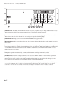
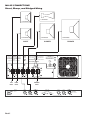
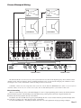
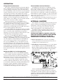
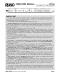
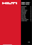
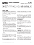
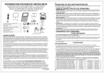
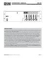
OPERATORS MANUAL
MA 6S
MULTICHANNEL AMPLIFIER
1
2
3
4
5
6
CLIP LIMIT
CLIP LIMIT
CLIP LIMIT
CLIP LIMIT
CLIP LIMIT
CLIP LIMIT
SOA LIMIT
SOA LIMIT
SOA LIMIT
SOA LIMIT
SOA LIMIT
SOA LIMIT
READY
READY
READY
READY
READY
READY
MA 6S
POWER
THERMAL
MULTI
CHANNEL
AMPLIFIER
BRIDGED
(INACTIVE)
BRIDGED
(INACTIVE)
BRIDGED
(INACTIVE)
LEVEL
+4
+10
4
6
LEVEL
+4
+10
4
6
LEVEL
+4
+10
4
6
LEVEL
+4
+10
4
6
LEVEL
+4
+10
4
6
LEVEL
+4
+10
4
6
POWER
+20
8
2
0
10
dBu 0
+20
8
2
0
10
dBu 0
+20
8
2
0
10
dBu 0
+20
8
2
0
10
dBu 0
+20
8
2
0
10
dBu 0
+20
8
2
0
10
dBu 0
QUICK START
You gots your good habits, and you gots your bad habits. A good habit is to read at least this much of the manual. A bad
habit is not to read any of this manual. Reading just this section can prevent grief worse than your worst nightmare. Grief
that's hard to get rid of—harder than a bad habit.
Be sure the amplifier is off before making any connections. Euroblocks make connecting and unconnecting the amplifier easy. They are just like little snap-on terminal blocks.The balanced Input blocks are green, and the speaker Output
blocks are black. Driving the MA 6S from a balanced source is recommended. If you just have to drive the MA 6S Input
with an unbalanced source, we recommend using cable that has two conductors with a shield. Connect the sources positive
or “hot” to the MA 6S’s +, the negative or ground to the MA 6S’s –, and connect the shield to the MA 6S’s SHIELD
(center of Euroblock connector). Do not connect the shield at the source end. Keep your input cable lengths as short as
possible. See the RaneNote, “Sound System Interconnection” for more information regarding this issue.
Speaker loads should be no less than four ohms per output. If you are running multiple speakers per channel in series or
parallel, check your impedances, and consider the KTM 6 Transformer Kit as an option (see Data Sheet). If you use 100V,
70.7V or 25V output transformers, you need to engage the 80 Hz High-Pass Filter jumpers as described on page Manual-6.
If you are running six separate channels (unbridged), be sure all the BRIDGED switches on the rear panel are depressed. If you are running any channels bridged, you are obviously a power user and we highly recommend you read
further into the manual regarding this issue.
With Input and Output connections completed, be sure all front panel LEVEL controls are all the way counterclockwise. Now flip the POWER switch and after hearing the relays click in after a second, notice that the READY lights come
on. Slowly turn up each channel's LEVEL control to the desired gain and if all is well you should hear something pleasant.
If not, re-check connections, put on a better CD, and read more of the manual.
WEAR PARTS: This product contains no wear parts.
Manual-1
FRONT PANEL DESCRIPTION
1
2
3
4
5
6
CLIP LIMIT
CLIP LIMIT
CLIP LIMIT
CLIP LIMIT
CLIP LIMIT
CLIP LIMIT
SOA LIMIT
SOA LIMIT
SOA LIMIT
SOA LIMIT
SOA LIMIT
SOA LIMIT
READY
READY
READY
MA 6S
POWER
THERMAL
MULTI
CHANNEL
AMPLIFIER
READY
READY
READY
BRIDGED
(INACTIVE)
BRIDGED
(INACTIVE)
BRIDGED
(INACTIVE)
LEVEL
+4
+10
4
6
LEVEL
+4
+10
4
6
LEVEL
+4
+10
4
6
LEVEL
+4
+10
4
6
LEVEL
+4
+10
4
6
LEVEL
+4
+10
4
6
POWER
+20
8
2
0
1
2
3
4
+20
10
dBu 0
8
2
0
5
10
dBu 0
6
+20
8
2
0
10
dBu 0
+20
8
2
0
10
dBu 0
+20
8
2
0
10
dBu 0
+20
8
2
0
10
dBu 0
7
햲 POWER switch: Obediently turns the MA 6S on and off every time you poke it with your finger (or other suitable object).
All six channels have delayed turn-on/instant turn-off relays to eliminate any switching transients.
햳 THERMAL Overload indicator: Lights red if the MA 6S becomes too hot, indicating that power has been removed from
all six channels. Be sure to check the fan filter and actual speaker impedances if this lights up.
햴 POWER indicator: Lights yellow whenever the MA 6S POWER switch (햲) is turned on.
햵 READY indicators: Light green whenever the mute relay is passing the signal through to the speaker. Normal operation is
the on status.
햶 SOA LIMIT indicators: Light red whenever a channel leaves the Safe Operating Area (SOA). This means the amplifier
turned down the Input level quickly and automatically, avoiding over-dissapation. Input signals 30 dB over a safe limit will
cause the READY indicator and mute relay to turn off until the amplifier has been turned off and the problem corrected.
Normal operation is the off status.
햷 CLIP LIMIT indicators: Light red whenever a channel’s Output cannot follow its Input. The amplifier has turned down
the Input level quickly and automatically, avoiding audible distortion. Normal operation is the off status.
햸 LEVEL controls: Determine the Input sensitivity of each respective amplifier channel. At its full clockwise position, an
Input signal of 0 dBu (.775 vrms) drives the amplifier to full power. As the controls are rotated counterclockwise, more
Input signal level will be needed to achieve full power. If the calibrations in gray appear backwards with respect to most
level controls, it is because they are Input sensitivity markings, not attenuation indications.
NOTE: To install the MA 6S security covers, which have been supplied with the amplifier in the form of six small black plastic
caps, set the six LEVEL controls to the desired position and then pull the knobs off. Insert the plastic covers in the now
vacant holes. You may then sleep soundly knowing that your amplifier installation cannot be mindlessly violated.
Manual-2
REAR PANEL DESCRIPTION
WARNING
MA 6S
CAUTION
CAUTION
TO REDUCE THE RISK OF FIRE OR ELECTRICAL SHOCK DO
NOT EXPOSE THIS EQUIPMENT TO RAIN OR MOISTURE. DO
NOT REMOVE COVER. NO USER SERVICEABLE PARTS
INSIDE. REFER SERVICING TO QUALIFIED PERSONNEL.
MADE IN U.S.A.
RANE CORP.
TO REDUCE THE RISK OF FIRE REPLACE ONLY WITH THE SAME
TYPE FUSE. DISCONNECT SUPPLY CORD BEFORE CHANGING FUSE.
TO PREVENT POSSIBLE INJURY
TURN UNIT OFF AND UNPLUG AC
LINE CORD BEFORE REMOVING FAN
FILTER GUARD FOR CLEANING.
ATTENTION
UTILISER UN FUSIBLE DE RECHNAGE DE MÊME. DÉBRANCHER
AVANT DE REMPLACER LE FUSIBLE.
AVIS
RISQUE DE CHOC ELECTRIQUE — NE PAS OUVRIR
ACN 001 345 482
120VAC UNIT: FUSE TYPE 3AB 15A/250VAC FB
230VAC UNIT: FUSE TYPE 3AB 8A/250VAC FB
120 V
50/60 Hz
1400 WATTS
TYPICAL
BLACK
5
+
–
+
–
RED +
BLACK
3
4
+
–
+
–
F
RED +
BLACK
6
BRIDGED SPEAKER
RED +
+
–
+
–
SIGNAL
GROUND
CHASSIS
GROUND
–
+
IN
(NOT
USED)
–
+
IN
OUTPUT POWER PER CHANNEL
100 WATTS / 8 Ω
150 WATTS / 4 Ω
300 WATTS / 8 Ω
CLASS 2
1
FOR CONTINUED GROUNDING
PROTECTION DO NOT REMOVE SCREW
1
2
E
BRIDGED SPEAKER
FUS
E
US
FUSE
BRIDGED SPEAKER
2
–
+
INPUT
–
+
IN
(NOT
USED)
–
+
IN
OUTPUT POWER PER CHANNEL
100 WATTS / 8 Ω
150 WATTS / 4 Ω
300 WATTS / 8 Ω
CLASS 2
–
+
INPUT
–
+
IN
(NOT
USED)
–
+
IN
OUTPUT POWER PER CHANNEL
100 WATTS / 8 Ω
150 WATTS / 4 Ω
300 WATTS / 8 Ω
CLASS 2
NORMAL
NORMAL
NORMAL
BRIDGED
BRIDGED
BRIDGED
3
–
+
INPUT
4
5
6
햲 INPUTS: These are balanced Euroblock connectors. Cable should include two wires with shield. Euroblocks accept up to
12 AWG wire. The shield may be attached to either chassis or signal ground. For unbalanced sources consult the included
RaneNote, “Sound System Interconnection.”
햳 OUTPUTS: Connect the speaker(s) to each of the six channels by means of the Euroblock connectors with 18 to 12 AWG
wire (See 햴 for Bridged operation).
햴 NORMAL/BRIDGED switch: With the switch in the out position and the red BRIDGED indicator on, the MA 6S is
operating in BRIDGED mode. The MA 6S utilizes the BRIDGE switch to make internal connections between each pair of
channels: 1&2, 3&4, and 5&6. Whenever a signal is connected to an odd numbered channel (say channel 1), the next
even-numbered channel is driven inverted when the BRIDGE switch is activated. Connect Inputs to odd amplifier channels
only (1,3,5), and connect speakers to the “+” terminals of each channel pair as shown in gray on the chassis silk-screen.
When the BRIDGE switch is inactive, the internal connection is defeated and both channels operate independently.
햵 AC line cord: Plug this into a grounded l20 VAC AC outlet (or 230 VAC if the MA 6S is internally wired for 230 V
operation).
햶 Line FUSE: For 120 volt operation, use only a 15 amp 250 volt Fast-blow (or Normal blow—not Slow blow) fuse, 1.25"
long, such as Buss ABC-15 or equivalent. For 230 volt operation use Buss AGC-8 or equivalent.
햷 Fan filter: This washable filter may easily be removed for periodic cleaning by gently pulling on the black plastic housing
and then lifting it away–perform this feat with the fan off, of course. Once the filter is removed, rinse it under hot tap water;
use dish soap to cut through particularly stubborn “tav sludge.” The MA 6S draws a tremendous amount of air to ensure
proper cooling and resultant long term reliability. Check and clean the filter as often as necessary, especially if the
THERMAL overload indicator ever comes on.
IMPORTANT: Keep this filter clean to ensure proper cooling and reliability of the MA 6S. Never remove the filter with the
unit plugged in.
Manual-3
MA 6S CONNECTIONS
Direct, Biamp, and Bridged Wiring
4 OHM MINIMUM
4 OHM MINIMUM
4 OHM MINIMUM
4 OHM MINIMUM
DIRECT
8 OHM MINIMUM
BIAMPED
BRIDGED
WARNING
MA 6S
CAUTION
CAUTION
TO REDUCE THE RISK OF FIRE OR ELECTRICAL SHOCK DO
NOT EXPOSE THIS EQUIPMENT TO RAIN OR MOISTURE. DO
NOT REMOVE COVER. NO USER SERVICEABLE PARTS
INSIDE. REFER SERVICING TO QUALIFIED PERSONNEL.
MADE IN U.S.A.
RANE CORP.
TO REDUCE THE RISK OF FIRE REPLACE ONLY WITH THE SAME
TYPE FUSE. DISCONNECT SUPPLY CORD BEFORE CHANGING FUSE.
TO PREVENT POSSIBLE INJURY
TURN UNIT OFF AND UNPLUG AC
LINE CORD BEFORE REMOVING FAN
FILTER GUARD FOR CLEANING.
ATTENTION
UTILISER UN FUSIBLE DE RECHNAGE DE MÊME. DÉBRANCHER
AVANT DE REMPLACER LE FUSIBLE.
AVIS
RISQUE DE CHOC ELECTRIQUE — NE PAS OUVRIR
120 V
50/60 Hz
1400 WATTS
ACN 001 345 482
120VAC UNIT: FUSE TYPE 3AB 15A/250VAC FB
230VAC UNIT: FUSE TYPE 3AB 8A/250VAC FB
TYPICAL
F
+
–
+
–
3
4
+
–
+
–
RED +
FOR CONTINUED GROUNDING
PROTECTION DO NOT REMOVE SCREW
1
2
+
–
E
BRIDGED SPEAKER
BLACK
5
6
FUS
E
US
FUSE
+
–
CHASSIS
GROUND
SIGNAL
GROUND
–
+
IN
–
+
IN
OUTPUT POWER PER CHANNEL
100 WATTS / 8 Ω
150 WATTS / 4 Ω
300 WATTS / 8 Ω
CLASS 2
NORMAL
–
+
–
+
IN
–
+
–
+
IN
–
+
IN
OUTPUT POWER PER CHANNEL
100 WATTS / 8 Ω
150 WATTS / 4 Ω
300 WATTS / 8 Ω
CLASS 2
(NOT
USED)
–
+
IN
OUTPUT POWER PER CHANNEL
100 WATTS / 8 Ω
150 WATTS / 4 Ω
300 WATTS / 8 Ω
CLASS 2
–
+
INPUT
NORMAL
BRIDGED
LEFT
INPUT
RIGHT
INPUT
BRIDGED
INPUT
HIGH OUT
LOW OUT
CHANNEL 2 IN
STEREO 2-WAY
HIGH OUT
LOW OUT
CHANNEL 1 IN
AC 22B
POWER
160mA
CLASS 2 EQUIPMENT
Manual-4
SUBWOOFER SWITCH MUST
BE SET TO 2-CHANNEL
FOR MONO 3-WAY
MADE IN U.S.A.
RANE CORP.
OMIT FOR MONO SUB
SYSTEM MODE
STEREO
MONO
2-WAY
3-WAY
SUBWOOFER
MONO SUB
2CHANNEL
PIN 2=POSITIVE
PIN 3=NEGATIVE
PIN 1=CHASSIS GND
MONO SUB OUT
Stereo Biamped Wiring
TWEETER
TWEETER
8 OHM WOOFER
8 OHM WOOFER
WARNING
MA 6S
CAUTION
CAUTION
TO REDUCE THE RISK OF FIRE OR ELECTRICAL SHOCK DO
NOT EXPOSE THIS EQUIPMENT TO RAIN OR MOISTURE. DO
NOT REMOVE COVER. NO USER SERVICEABLE PARTS
INSIDE. REFER SERVICING TO QUALIFIED PERSONNEL.
MADE IN U.S.A.
RANE CORP.
TO REDUCE THE RISK OF FIRE REPLACE ONLY WITH THE SAME
TYPE FUSE. DISCONNECT SUPPLY CORD BEFORE CHANGING FUSE.
TO PREVENT POSSIBLE INJURY
TURN UNIT OFF AND UNPLUG AC
LINE CORD BEFORE REMOVING FAN
FILTER GUARD FOR CLEANING.
ATTENTION
UTILISER UN FUSIBLE DE RECHNAGE DE MÊME. DÉBRANCHER
AVANT DE REMPLACER LE FUSIBLE.
AVIS
RISQUE DE CHOC ELECTRIQUE — NE PAS OUVRIR
120 V
50/60 Hz
1400 WATTS
ACN 001 345 482
120VAC UNIT: FUSE TYPE 3AB 15A/250VAC FB
230VAC UNIT: FUSE TYPE 3AB 8A/250VAC FB
TYPICAL
+
–
BLACK
3
+
–
+
–
F
+
–
RED +
4
RED +
FOR CONTINUED GROUNDING
PROTECTION DO NOT REMOVE SCREW
1
2
+
–
E
BLACK
5
6
FUS
E
US
FUSE
BRIDGED SPEAKER
BRIDGED SPEAKER
+
–
CHASSIS
GROUND
SIGNAL
GROUND
–
+
IN
–
+
IN
OUTPUT POWER PER CHANNEL
100 WATTS / 8 Ω
150 WATTS / 4 Ω
300 WATTS / 8 Ω
CLASS 2
–
+
–
+
IN
(NOT
USED)
–
+
–
+
IN
OUTPUT POWER PER CHANNEL
100 WATTS / 8 Ω
150 WATTS / 4 Ω
300 WATTS / 8 Ω
CLASS 2
–
+
IN
(NOT
USED)
–
+
IN
OUTPUT POWER PER CHANNEL
100 WATTS / 8 Ω
150 WATTS / 4 Ω
300 WATTS / 8 Ω
CLASS 2
INPUT
–
+
INPUT
NORMAL
BRIDGED
BRIDGED
HIGH OUT
LOW OUT
CHANNEL 2 IN
STEREO 2-WAY
HIGH OUT
LOW OUT
CHANNEL 1 IN
AC 22B
POWER
160mA
SUBWOOFER SWITCH MUST
BE SET TO 2-CHANNEL
FOR MONO 3-WAY
MADE IN U.S.A.
RANE CORP.
OMIT FOR MONO SUB
SYSTEM MODE
STEREO
MONO
2-WAY
3-WAY
SUBWOOFER
MONO SUB
2CHANNEL
PIN 2=POSITIVE
PIN 3=NEGATIVE
PIN 1=CHASSIS GND
MONO SUB OUT
CLASS 2 EQUIPMENT
CHANNEL 2 INPUT
CHANNEL 1 INPUT
The MA 6S will drive an active two-way stereo system when wired as shown. The high frequency drivers run direct from
channels 5 and 6. The low frequency drivers, requiring much more power, are run from two bridged pairs: Channels 1 and 2
are bridged to one woofer, and channels 3 and 4 are bridged to the second woofer.
CAUTION: 8 ohms is the lowest impedance that can be driven by the MA 6S in BRIDGED mode. If there are two woofers in
each bass cabinet, be sure they are wired in series if they have an individual impedance of less than 16 ohms each.
Chassis Grounding
Whenever connecting any device to the MA 6S Inputs, be aware of signal grounding paths. Connect the shield to MA 6S
Chassis Ground for proper cable shielding. Some installations may permit ground connection to Signal Ground on the
Euroblock, but the best ground is directly to the Chassis.
In addition, since the AC 22B does not get it's ground through the line cord, its chassis should be grounded through either
the rack rails or a jumper wire connecting the chassis’ of both units.
See the included RaneNote, “Sound System Interconnection” for a full explanation and proper wiring techniques.
Manual-5
OPERATION
Voltage Controlled Attenuators
The voltage controlled attenuators (VCAs) in the MA 6S
allow a significant increase in usable volume levels without
excessive clipping or interference from conventional distortion causing muting circuits. The VCAs do not affect dynamic
response, distortion or noise levels of any material within the
rated output specifications of the amplifier. They simply
monitor the difference between Input and Output signals, and
the power dissipated in the output devices. In the event of
clipping or excessive dissipation in the output devices, the
VCAs “jump in” (out of hiding, as it were) and turn down the
Input level to correct the overdrive condition.
This means that whenever a CLIP LIMIT flashes, a
musical peak has been quickly turned down to avoid excessive clipping. This allows you to run the amplifier at a higher
continuous level, typically about 4 dB SPL higher than
without VCAs. And that 4 dB of increased SPL is the equivalent of a 250 watt amplifier without VCAs.
If an SOA LIMIT flashes, the Input level has been quickly
turned down to prevent over-dissipation in the output devices
due to excess phase shift or abnormally low impedances
which may occur at some frequencies. This protection occurs
without distorting or interrupting the program.
Keep an eye on the LEDs on the MA 6S front panel.
Occasional flashing of a CLIP LIMIT and/or occasional
flashing of a SOA LIMIT means you are getting the most SPL
out of the amplifier. Continual lighting of either LED indicates excessive input overdrive, or too low impedance of
load. If a green READY goes off, a load has been encountered that could not be corrected by the VCAs, or the amplifier has offset. If this occurs, the amplifier must be turned off
and the problem corrected before the channel can be operated.
If the READY LED will not light with the load disconnected,
then an internal fault has occurred and the amplifier is in need
of repair.
About the MA 6S and Circuit Breakers...
The MA6S will easily deliver over 900 watts of audio
power, which requires as much as 15 amps of current from
the AC outlet. 15 amps is not an uncommon value for
household and some institutional circuitbreakers, though 20
amp versions are becoming more common. The bottom line is
that the MA 6S is capable of tripping a 15 amp circuit breaker
under normal operation. An amp that delivers a lot of power,
drinks a lot of power to do so.
It is not likely that you will trip a breaker, but it is wise to
be aware of the possibility so you don’t panic if it happens.
INTERNAL JUMPERS
Each amplifier card contains a jumper block that gives the
option of inserting an 80 Hz High-Pass Filter into the Input
signal. This is required in 70 or 100 volt systems when
excessive bass can saturate the transformers, reduce the
output, and possibly blow a fuse at high output levels.
The MA 6S is shipped with these jumpers in the out
position (filters defeated). Moving this jumper to the in
position activates the filter.
CAUTION: WAIT ABOUT 15 MINUTES AFTER THE
AMPLIFIER HAS BEEN POWERED DOWN BEFORE
BEGINNING DISASSEMBLY, TO ALLOW THE
POWER SUPPLY CAPACITORS TO DISCHARGE.
1. Remove the bottom cover: 4 each #6 x 3/8" phillips
screws on the bottom of the side rails and 12 each #6 x 1/
4" phillips screws on the bottom cover.
2. 80 Hz High-Pass Internal Jumpers: To access the jumper
on each amplifier card, locate J2 (LOW FILTER). The
MA 6S is shipped with these jumpers in the OUT position
(filters defeated). Moving this jumper to the IN position
activates the filter.
V
Adapting the MA 6S to Your Changing Needs
With six channels to choose from and built-in Bridging,
there are a number of different combinations available to suit
your present and growing needs. The nice thing about the
MA 6S is that you can re-configure it instead of losing money
on an obsolete, used piece of gear you no longer need.
You can start out with 6 channels at 100 watts or three
channels at 300 watts. When the time comes, you can step up
to six channels at 300 watts by obtaining another MA 6S and
keeping the original. Upgrading to biamped monitors or
tri-amped mains becomes easy as well, by simply adding a
second MA 6S, both taking up only 10.5" rack space.
In the event that 80 Hz is not a high enough cutoff
frequency, values may be changed to replace 3 resistors on
each amplifier card. This operation requires dissasembly and
soldering as outlined in the MA 6S SERVICE INFORMATION section, and should only be performed by qualified
service personnel.
©Rane Corporation 10802 47th Ave. W., Mukilteo WA 98275-5098 TEL (425)355-6000 FAX (425)347-7757 WEB http://www.rane.com
Manual-6
107213