1
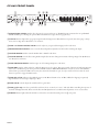
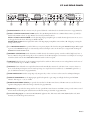
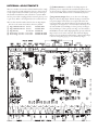
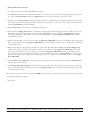
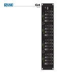
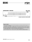
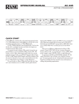
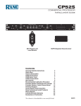
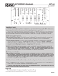
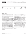
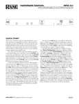
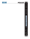
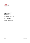
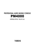
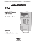
OPERATORS MANUAL
CP 64S
COMMERCIAL PROCESSOR
PAGING
ZONE ASSIGN
PAGE 1
PAGE 2
1 2
1 2
RMT
1&2 RMT
1&2
ZONE 2
LINE 1
LINE 2
LINE 3
4
6
4
6
4
6
4
6
4
6
0
10
0
10
0
10
0
10
0
10
2
ACTIVE
PROGRAM INPUT LEVELS
LEVEL
ZONE 1
8
2
8
2
8
2
8
2
ZONE 1
DUCKER
DEPTH
PRIORITY
8
4
6
0
10
2
ZONE 2
PROGRAM
SELECT
L2 L3
L1
P
8
LEVEL
4
2
OFF
ON
ACTIVE
10
ZONE 1
PROGRAM
SELECT
L2 L3
L1
P
8
0
RMT
DUCKER
DEPTH
6
SIG OL
•
ON
SIG OL
6
CP 64S
•
0
COMMERCIAL
PROCESSOR
•
8
0
RMT
12
6
2
OFF
ZONE 2
+
LEVEL
4
6
•
10
12
40
100
250
630
1.6k
4k
10k
40
100
250
630
1.6k
4k
10k
POWER
QUICK START
If you were the type that cheated on school book reports by just
skimming through the reading assignments, then this section is
for you! It gives you not quite enough information to really know
what you’re doing. But, if you follow the recommended set up
procedure, you should get at least a “B.”
Keep the amplifiers and the CP 64S turned off until all connections are made.
INTERNAL SETTINGS
Access to the following internal controls requires removal of the
top cover. All internal settings should be complete before you install the CP 64S, before you attach the power cable. The factory
default settings work for many applications. However, you may
need to change one or more for your system. See the INTERNAL
ADJUSTMENTS description on page Manual-4 for more details.
• Each Page Input has a 15 volt Phantom Power switch. The
default is off.
• The Page Priority switch assigns priority override to Page 1,
Page 2 or NO (none). The default is Page 1. If a Page has
priority, it overrides the non-priority Page in the Zone(s) it is
assigned. The NO priority setting allows the Pagers to mix.
• Each Page Input may sum with the Program Pre- or PostVCA. When set to Pre-VCA, Zone Level, EQ and Limiter
circuits act upon the Page. When summed Post-VCA, the
Page is not influenced by Zone Level, EQ or Limiter circuits.
The default is Pre-VCA.
• The Zone 1 Stereo/Mono switch default is Stereo.
• There are two internal trim controls for the Program Priority
detector. The Program Priority Threshold trim has a range of
-∞ to -35 dBu with a default of -50 dBu. The Program Priority
Release Time has a range of 2 to 20 seconds. The default is 12
seconds.
PAGE INPUTS
Connect Page Inputs to the Euroblock on the rear panel and
select the appropriate MIC or LINE switch position for each.
First, set the gain with the Page TRIM control, then set the Page
DETECT THRESHOLD and finally the Page Zone LEVEL.
PR 2 REMOTE
If you use the optional PR 2 remote (sold separately), wire it to
the rear RMT ZONE ASSIGN Euroblock as indicated. If you
WEAR PARTS: This product contains no wear parts.
require remote control but do not wish to use a PR 2, any simple
switch closure to GND will work. These inputs are also TTL
compatible (0 to 5 VDC). See wiring details on page Manual-5.
PROGRAM INPUTS
Connect Program sources to the RCA PROGRAM INPUTS.
If you have a priority program, like a jukebox, connect it to the
PRIORITY Input. The Program PRIORITY ASSIGN switch
assigns priority override to Off, Zone 1, Zone 2, or Both. In the
Zone(s) that it is assigned, the priority program is automatically
selected when signal is detected.
EXPAND OUTPUTS
Wire the EXPAND OUTPUT Euroblock for each Zone as
required. These are cross-coupled line drivers and may be used
balanced or unbalanced. Each Expand Output can be Page-only,
Program-only or its Zone signal. The Zone source will not include
the Page if the Page is summed Post-VCA. Page is always available from the Page source.
ZONE OUTPUTS
Wire the two ZONE OUT Euroblocks as required. These are
cross-coupled line drivers and may be used balanced or unbalanced. Set the LIMIT threshold as required.
ZR 1 REMOTE
You may use one or two ZR 1 Remotes with each CP 64S. If
you use the optional ZR 1 remote (sold separately), wire it to the
rear REMOTES Euroblock as indicated. If a ZR 1 remote is not
used, any simple switch closure to ground will work for the D0
and D1 pins. These pins are TTL compatible (0 to 5 VDC). The
logic is inverse Gray Code. Any ground referenced 5 volt DC
control may be used as the input to V1 or V2 . Do not ground the
Vr1 or Vr2 pins. See wiring details on page Manual-5.
SETUP ADVICE
The CP 64S is very versatile. While this makes a large number of
system applications possible, it also results in complexity. For this
reason, it is important to use an organized approach for setup and
calibration. A highly recommended setup procedure appears on
page Manual-7. By following it you will encounter fewer problems and reduce the need to increase our collective phone bills.
Manual-
CP 64S FRONT PANEL
1
6 80
PAGING
ZONE ASSIGN
PAGE 1
PAGE 2
1 2
1 2
RMT
1&2 RMT
1&2
ZONE 2
LINE 1
LINE 2
LINE 3
4
6
4
6
4
6
4
6
4
6
0
10
0
10
0
10
0
10
0
10
2
ACTIVE
PROGRAM INPUT LEVELS
LEVEL
ZONE 1
8
2
8
2
8
2
8
2
8
4
6
0
10
2
3
4
ZONE 2
PROGRAM
SELECT
L2 L3
L1
P
8
LEVEL
4
ON
DUCKER
DEPTH
6
2
OFF
10
ZONE 1
PROGRAM
SELECT
L2 L3
L1
P
8
0
RMT
ACTIVE
2
ZONE 1
DUCKER
DEPTH
PRIORITY
•
ON
SIG OL
SIG OL
6
CP 64S
•
0
COMMERCIAL
PROCESSOR
•
8
0
RMT
12
6
2
OFF
ZONE 2
+
LEVEL
4
6
•
10
12
40
100
250
57 9
630
1.6k
4k
10k
40
100
250
630
1.6k
4k
q
10k
POWER
w
1 Paging Zone Assign switches select the zone(s) a page signal is sent to. The RMT position activates the rear panel RMT
ZONE ASSIGN port, allowing the optional PR 2 wired remote to assign the active page Zone(s).
2 Active indicators light when a page input signal reaches the Page Detect Threshold (see rear panel). Note that a page is always
Active when its Page Detect Threshold is set to minimum.
3 Zone 1 and Zone 2 Paging Level controls adjust (as you guessed) the Paging Level in each Zone.
4 Program Input LevelS “stereo”controls allow independent adjustment of the level for each Program Input.
5 Ducker OFF/ON switches turn the Ducker ON or OFF for each Zone.
6 Ducker Depth controls allow setting Ducker Depth (the amount of Program attenuation during a Page) from 50 dB (ccw)
to 6 dB (cw) for each Zone.
7 Zone Program Select switches assign one of four Program Inputs to each Zone.
8 Zone RMT switches, when pushed in, enable the Remotes port for a Zone. This turns control of Zone Level and Zone Program
Select over to the Remotes port. Front panel Zone LEVEL and Zone PROGRAM SELECT controls are inactive when RMT is
selected. Two optional wired ZR 1 remotes may be connected to the Remotes port. An object smaller in diameter than the switch
button is required to engage the RMT switches.
9 Zone SIG and OL indicators show SIGnal present at -20 dBu and OverLoad at -16 dBu (4 dB before clipping) respectively.
Signal indicators are located pre-EQ and pre-VCA.
0 Zone Level controls adjust the overall Level for a given Zone.
q ZONE graphic EQ controls are provided for each Zone. Zone 1 controls are “stereo,” with each slider controlling the response of
both Left and Right channels. These controls allow ±12 dB adjustment of seven ISO center frequencies on two octave centers.
w POWER indicator lights when the CP 64S is connected to its needed electrical power. See q, rear panel.
Manual-
CP 64S REAR PANEL
CP 64S
COMMERCIAL AUDIO
EQUIPMENT 24TJ
100-240 V
50/60 Hz 12 WATTS
Z2 PGM
Z2 LEVEL
ACN 001 345 482
q
LIMITER
ZONE 1
ZONE 2
MIN
MAX
Vr Vc
ZONE 2
EXPAND OUT
Z1 PGM
D1 D0
+8
ZONE 1
EXPAND OUT
ZONE PAGE ZONE PAGE
Z1 LEVEL 2
1
Vr Vc
PGM
PGM
0
PROGRAM INPUTS
Z2 EXPAND Z2 MONO
WIRING
R
RANE CORP. MADE IN U.S.A.
OUTPUTS
REMOTES
7
–20
Z1 EXPAND Z1 RIGHT
+ –
+ –
6
Z1 LEFT
+ –
+8
+20
–20
PRIORITY
ASSIGN
ZONE
off 1
+20
THIS DEVICE COMPLIES WITH
PART 15 OF THE FCC RULES FOR
A CLASS 'B' COMPUTING DEVICE.
L
REMOTE 1
REMOTE PAGE
ZONE ASSIGN WIRING
L
INPUT 1
PAGING INPUTS
PAGE 1
TRIM
PAGE 2
TRIM
Z1 Z2
2
1&2
R
PRIORITY
5 4
R
3
2
3
PAGE 2
1
+30
+60
MIC
LINE
PAGE 1
DETECT THRESHOLD
8
REMOTE 2
Z2 Z1
INPUT 2
+ –
91
OL +30
MIC
+60
LINE
2
1 PagING Input Euroblock connectors may be operated balanced or unbalanced. See CP 64S Connections on page Manual-3.
2 PagE 1 and PAGE 2 Input Mic / Line switches select 30 dB Input Pads when set to LINE. Phantom Power (if enabled) is
disabled when LINE is selected. See page Manual-4 to internally set Phantom Power.
PagE 1 and PAGE 2 Input Trim controls adjust Page Input preamplifier gain to match the microphone/source in use, not to
set the page level in the Zones. The range is 30 dB to 60 dB.
Paging INPUTS OL indicator lights when either of the Page Input preamplifiers comes within 3 dB of clipping, assisting the
setting of these trims.
3 Four Program Inputs are provided. Three are non-priority Inputs. The fourth is a Program PRIORITY Input. When signal
is present at the PRIORITY Input, it is automatically selected as the Input source in the Zone(s) it is assigned with the Program
PRIORITY ASSIGN ZONE switch.
4 Priority Assign ZONE switch determines in which Zone(s) the automatic priority override is enabled. Off (none), Zone 1,
Zone 2 or Both are the possible settings. If you do not intend to use the Priority Input as an automatic override Input, do not assign
it with this switch. Use the Zone PROGRAM SELECT switch on the front panel.
5 LimitER threshold controls set the maximum output level for each Zone. These circuits are true voltage limiters with a ratio of
15:1. The threshold range is -20 dBu to +20 dBu.
6 OutputS feature balanced cross-coupled line drivers with a Euroblock connector for each Zone. Zone 1 is stereo. Zone 2 is
mono, and both Expand outputs are mono. When operating cross-coupled line drivers unbalanced, it is essential to ground the (–)
pin. See CP 64S Connections on page Manual-3.
7 ZONE Expand OUT switches assign Page-only, Program-only or Zone 1 or Zone 2 as the source for each Expand Output.
8 Detect Threshold sets the Paging input signal level required to gate a Page on and light the front panel ACTIVE
indicator. The range is -∞ (on) to +4 dBu.
9 REMOTE PAGE Zone Assign port provides the interface for the PR 2 wired remote. The PR 2 remote is used for Zone assignment of Page Inputs. Follow the wiring as described on page Manual-5.
0 Remotes ports provides the wiring interface for two optional ZR 1 wired remotes. Each ZR 1 remote provides remote control
of Zone Level and Zone Program Select functions. Follow the wiring as described on page Manual-5.
q Universal Voltage Input: via a miniature IEC 60320 C6 appliance inlet. This mates with an IEC 60320 C5 line cord (USA
domestic). Do not lift the ground connection!
Manual-
INTERNAL ADJUSTMENTS
There are a number of controls inside the CP 64S used to configure the system for specific applications. Access to these controls
is only required once before initial system setup. Do this before
the CP 64S is installed in a rack or wired into a system. Make
sure the power cable is unplugged before removing the top cover
to gain access. Refer to the diagram below for control locations.
There are five internal switches related to the two Page Inputs.
The dot on the circuit board shows the factory default:
1 Page 1 Phantom Power 15VDC
Default: OFF
2 Page 2 Phantom Power 15VDC
Default: OFF
3 Page Priority
P1, NO, P2 Default: P1
4 Zone 1 Page Sum Pre- or Post-VCA Default: Pre-VCA
5 Zone 2 Page Sum Pre- or Post-VCA Default: Pre-VCA
1 2 Phantom Power is available for both Page Inputs. If
phantom power is required for the intended microphone, then
set the appropriate switch to ON. If a Paging Input Mic / Line pad
switch is set to LINE, Phantom Power is automatically defeated.
3 Page Priority Assign allows you to select one of the Page
Inputs as a Priority Page Input. The Priority Pager overrides the
non-priority Pager in the Zone(s) it is assigned. Note that the
non-priority Pager may still broadcast in any Zone that the Priority Pager is not assigned to or not currently broadcasting in. Set
the switch to P1 if you wish Page 1 to have priority over Page 2.
If you wish Page 2 to have priority over Page 1, set the switch to
P2. If NO is selected, neither Paging Input has priority and both
Pagers may be active at the same time. This allows the Paging
Inputs to mix for applications like karaoke or PA. If a Page Input
is used for emergency paging, set it as the Priority Pager.
6
1
2
7
3
8
4 5
Manual-
4 5 The Zone 1 Page and Zone 2 Page switches allow you to
sum Page signals with Program signals “Pre” (before) or “Post”
(after) the VCA. The VCA is used for Zone Level control and
Limiting. Therefore, if you require the Page Level to be controlled independent of the Program Level, set the switch for that
Zone to “Post.” This is the desired setting for emergency paging.
If “Pre” is selected, Paging signals sum with Program signals
before the VCA. In this instance both Page and Program signal
levels are affected by the front panel ZONE LEVEL control.
Note the following:
• Zone Level, EQ and Limiter circuits do not affect Page signals
summed Post-VCA.
• Zone Level, EQ and Limiter circuits do affect Page signals
summed Pre-VCA.
• Page signals are not available on the Expand Zone output
when summed Post-VCA.
• Page signals are always available for the Expand Page output.
There are two internal controls related to the Program Priority
detector:
6 Priority Release Time 2 sec to 20 sec (trim pot)
Default: 12 seconds
7 Priority Threshold
-∞ to -35 dBu (trim pot)
Default: -50 dBu
The default settings for the Program Priority detector are
chosen for most applications. Detector Threshold settings lower
than the default setting of -50 dBu are prone to false triggering unless the source is very quiet. If a source is noisy, you may
wish to set the threshold higher to prevent false triggering. The
default Release Time is 12 seconds. You may wish to decrease
the Release Time if the source is a TV, radio, tape machine or
any other relatively constant signal source. If you have a source
like a jukebox, with relatively long search times, you may wish to
extend the Release Time.
There is one internal control related to Zone 1:
8 Zone 1 Mode
Mono/Stereo
Default: Stereo
CP 64S CONNECTIONS
Do not connect the power cable to the CP 64S until all other
connections are made.
All Input and Output connections are made with Euroblock
connectors except for the RCA Program Inputs. When wiring
to Euroblocks, a minimum wire gauge of 22 is preferred for
reliability (maximum 12 guage). If the ground or shield wire
is left shorter, it acts as a strain relief for the other wires. Cable
with a flexible jacket is easier to use and less likely to damage the
connections. Avoid stripping excess insulation. Inspect wires for
nicks that may lead to wire breakage. Fully insert each wire in
the appropriate socket and tighten the screw.
Page Input circuits are true instrumentation amplifier inputs
and operate balanced or unbalanced. Expand and Zone Outputs
are driven by high quality cross-coupled line drivers and operate
balanced or unbalanced. For both Inputs and Outputs, wiring
is basically the same. Balanced operation is recommended. Balanced wiring is straight forward, (+) to (+), (–) to (–) and shield
to shield.
For unbalanced operation, we recommend using two conductor cable with shield. The cable is wired to the CP 64S the same
as for balanced operation. At the other end of the cable, connect
the (+) wire to signal “hot” and both the (–) and shield wires to
ground (important.)
If you use single conductor cable with shield, connect the
shield/gnd wire to both the (–) and shield pins at the CP 64S. At
the other end of the cable connect the (+) wire to the signal “hot”
and the shield/gnd wire to ground. When unbalanced wiring
is used, it is very important for the CP 64S and any other unit
in the system to have good earth or technical grounds. If a unit
is located far from the CP 64S or is of a type that might create
grounding problems, isolation transformers should be used.
When operating cross-coupled line drivers unbalanced (i.e., any
CP 64S Output), it is essential to ground the (–) pin.
The four stereo Program Inputs connect to RCA jacks. These
Inputs are unbalanced. The same guidelines given above for
unbalanced operation apply to these Inputs.
See the RaneNote Sound System Interconnection (included in
this booklet) to answer any uncertainties, especially when using
unbalanced sources.
REMOTE INSTALLATION
The CP 64S supports wired remotes for Page Assign, Zone Level
and Zone Source selection. Wire lengths of up to 1000 feet are
possible. A brief list of suitable wire types is provided in the
WIRE TYPES section on the next page.
The PR 2 remote provides Page Zone Assign for Page 1 and
Page 2 inputs and is usually located at the Page source. If your
application requires one of the two PAGE ASSIGN switches to
control both Page 1 and Page 2 Assign, simply wire all Page 1
and Page 2 ports in parallel. You may leave the knob off the
unused control and cover it with one of the hole plugs provided
in the kit. If your installation requires Page 1 and Page 2 remote
control at two different locations, only three wires are required
for each PR 2 remote (Z1, Z2 & GND). As above, you may leave
the knob off the unused control and cover it with a hole plug.
The ZR 1 remote provides Zone Level and Source Selection,
allowing local control from inside the Zone. Two ZR 1 remotes
may be used (only use one in each Zone). If only one of the two
controls is used, you may cover the unused control with one
of the hole plugs provided in the kit. If you require one ZR 1
remote to control both Zones, simply wire the ports in parallel.
This may be done with Program Select only, Level only or both.
If only one of the two controls is wired in parallel, the other is
still available for a second remote.
When paralleling one remote across multiple CP 64S’s, all
three control pins must be wired, including the shields.
Keep the power cable unplugged to the CP 64S until all
connections are made. It is important to ensure that the CP 64S
Remote Ports are not subjected to sustained voltages outside the
range of 0 to 5 volts DC or high levels of static. Inputs are protected, however, caution is the better part of… you know. It is a
good idea to install the wiring, connect it to the remote assemblies and then make the final connections at the CP 64S. Do not
short Vr1 or Vr2 pins to ground. These pins are current limited,
however, excess heat is generated in the 5 volt supply if a short
occurs. Never subject the Vr1 or Vr2 pins to voltages above 5 volts.
Manual-
REMOTE MOUNTING
The ZR 1 and PR 2 remote assemblies mount in a standard U.S.
electrical box with a minimum depth of 2.25". Be sure to note
the wire color of each input in order to facilitate correct wiring
to the CP 64S. Connect each wire to the Euro connector by fully
inserting it in the correct socket and tightening the screw. Make
sure wires are free of nicks and that the cable jacket is stripped
back sufficiently to allow it to lie in the electrical box with the
remote assembly inserted. Use the flat head #6 screws supplied
with the kit to mount the remote assembly and silk-screened
front panel to the electrical box (see above diagram). Note the
“UP” arrow screened on the printed circuit board of each remote
(mount it pointing up).
The silk-screened front panel metal is painted on both sides.
This allows you to custom silk-screen the panel or add your own
custom decals. Simply install the modified front panel with your
art facing out, and you are in business!
Install each knob so that the line on the knob is properly
aligned with the silk-screening on the front panel of the remote
assembly. Install any Decora plate of your choice. For a secured
installation, you may wish to leave the knobs off and use a blank
Decora plate to cover the remote after adjustment.
WIRE TYPES
Variations in wire type do not greatly affect the performance of
the remote controls. 22-gauge stranded wire with a flexible jacket
is recommended. You may use 5-conductor unshielded remote
control signal cable for shorter runs (less than 200 feet [60
meters]), or 4-conductor (2 pair) shielded remote control signal
cable (use the shield as the ground return) for longer runs (200
to 1000 feet [60 to 300 meters]). The type of wire required is
influenced by your installation and local electrical codes.
Rane Corporation does not provide or source cable. Please
contact your local retail or wholesale outlet, not the factory. The
following is a short list of suitable cable types:
CONSOLIDATED ELECTRONIC WIRE AND CABLE
Plenum cable:
Unshielded remote control signal cable CAT. # 9896
Shielded remote control signal cable CAT. #9877, CAT. #9852
WEICO WIRE & CABLE INC.
Communication and control cable:
Multiconductor, unshielded CAT. #7606
ALPHA
Communication and control cable:
Multiconductor, unshielded CAT. #1175C
BELDEN
Unshielded remote control signal cable CAT. # 88741
Shielded remote control signal cable CAT. # 88723
S1B
10
J1A
Zone / Volume
4
6
0
10
2
8
LEVEL
S1A
2
D0
5
3
CW
3
PROGRAM SELECT
1
4
Vc
2
4
3
2
1
GND
GND
R1
2KRD
1
ZR 1
P
Decora plate (not included)
L1
L2 L3
D1
9
8
7
6
GND
5
Vr
5 POS TERM
ZONE REMOTE (ZR 1)
S2B
10
OFF
PR 2
Z1 Z2
BOTH
PAGE 1 ASSIGN
Paging Assign / Volume
OFF
Z1 Z2
BOTH
PAGE 2 ASSIGN
Manual-
Decora plate (not included)
J1A
Z2
PAGE 1
Z1
GND
5
S2A
4
5
3
Z1
Z2
2
GND
4
3
2
1
S1B
GND
9
8
7
6
GND
5
1
5 POS TERM
10
PAGE REMOTE (PR 2)
4
3
2
1
S1A
GND
PAGE 2
9
8
7
6
GND
RECOMMENDED CALIBRATION PROCEDURE
The CP 64S is a very versatile instrument. While this allows it to conform to the requirements of a large number of system applications, it also results in complexity. For this reason, it is very important to use an organized approach to system calibration. Once the
internal switches are set and the system is connected, take the time for proper calibration. The following is an ordered list of system
adjustments that should make calibration easy and result in optimum performance. Most important:
• Program Priority Assignrear panel
off
• Limiters
rear panel
+20 dBu
• Duckers
front panel
OFF
• Page Zone Levels
front panel
Min
• Remote Controls
front panel
not selected
• Paging Zone Assigns front panel
1&2 (both)
PAGING
ZONE 1
4
6
0
10
2
ACTIVE
CP 64S
PROGRAM INPUT LEVELS
LEVEL
ZONE ASSIGN
PAGE 1
PAGE 2
1 2
1 2
RMT
1&2 RMT
1&2
ZONE 2
8
4
6
0
10
2
LINE 1
8
4
6
0
10
2
LINE 2
8
4
6
0
10
2
LINE 3
8
4
6
0
10
2
ZONE 1
DUCKER
DEPTH
PRIORITY
8
4
6
0
10
2
COMMERCIAL AUDIO
EQUIPMENT 24TJ
Z2 LEVEL
0
ACN 001 345 482
Z1 PGM
D1 D0
6
10
4
ON
+8
+20
–20
off 1
+20
THIS DEVICE COMPLIES WITH
PART 15 OF THE FCC RULES FOR
A CLASS 'B' COMPUTING DEVICE.
COMMERCIAL
PROCESSOR
•
6
•
12
SIG OL
40
PRIORITY
ASSIGN
ZONE
CP 64S
•
0
8
10
100
250
630
1.6k
PROGRAM INPUTS
–20
Z1 LEFT
+ –
6
6
0
RMT
+8
Z1 EXPAND Z1 RIGHT
+ –
+ –
12
•
Z2 EXPAND Z2 MONO
ZONE 1
EXPAND OUT
ZONE 2
+
LEVEL
2
OFF
LIMITER
ZONE 1
ZONE 2
ZONE PAGE ZONE PAGE
Z1 LEVEL 2
1
Vr Vc
PGM
PGM
ZONE 1
PROGRAM
SELECT
L2 L3
L1
P
SIG OL
WIRING
ZONE 2
EXPAND OUT
DUCKER
DEPTH
8
ON
MIN
MAX
Vr Vc
R
RANE CORP. MADE IN U.S.A.
OUTPUTS
REMOTES
4
2
OFF
RMT
Z2 PGM
LEVEL
8
ACTIVE
100-240 V
50/60 Hz 12 WATTS
ZONE 2
PROGRAM
SELECT
L2 L3
L1
P
L
4k
10k
40
100
250
REMOTE 1
REMOTE PAGE
ZONE ASSIGN WIRING
L
630
INPUT 1
1.6k
10k
4k
PAGING INPUTS
PAGE 2
TRIM
Z1 Z2
POWER
PAGE 1
TRIM
2
1&2
R
PRIORITY
R
3
2
PAGE 2
1
+30
+60
MIC
LINE
PAGE 1
DETECT THRESHOLD
REMOTE 2
Z2 Z1
INPUT 2
+ –
OL +30
MIC
+60
LINE
Make sure the power is disconnected!
Control Presets:
Page settings (repeat for second page input):
• Input Pad
rear panel
• Input gain trim rear panel
• Detect Threshold
rear panel
• Paging Zone Assign
front panel
• Paging Level, Zone 1 front panel
• Paging Level, Zone 2 front panel
• Phantom Power
internal
• Pre/Post summing
internal
• Page Priority
internal
MIC or LINE as required
Center (12:00)
Min (CCW, active)
1&2 (both)
Min
Min
As required. Default Off
As required. Default Pre-VCA
As required. Default Page 1
Program Input settings:
• Priority Assign Zone
• Program Input Levels
• Priority Threshold
• Priority Release Time
off
Min
Set to -50 at factory (internal adjust -∞ to -35 dBu)
Set to 12 sec. at factory (internal adjust 2 to 20 sec.)
rear panel
front panel
internal
internal
Zone Settings (repeat for second zone):
• Expand Out
rear panel
• Limiter Threshold
rear panel
• Zone Level
front panel
• Program Select
front panel
• Ducker
front panel
• Ducker Depth
front panel
• RMT (Remote)
front panel
• EQ
front panel
• Stereo / Mono switch internal
As required (Zone/Program/Page)
CW, +20 dBu
Max
L1 (if your input is on L1).
OFF
Center (about 15 dB)
Out
Flat (center detent position)
As required (Zone 1 only, default:stereo)
System Connections:
• Connect page mics or line-level paging source
• Connect Program sources
• Connect Outputs to amplifiers
• Connect Remotes
You are now ready to calibrate the CP 64S…
Manual-
…CP 64S Calibration (continued)
1. Connect the power cord and verify the Power indicator lights.
2. Verify Zone Level controls are set to Maximum and that you have an active source for each of the Program Inputs you intend to
use. Select each Program Input and adjust its Input Level control to be the very loudest you would ever desire.
3. Adjust the rear panel Zone Limiter thresholds so that they just start to audibly reduce the output level. This ensures the level in a
Zone will never be louder than the maximum level you just set. If you wish one of the Zones to have a lower maximum loudness,
lower the Zone Limiter threshold accordingly.
4. Turn the Zone Level controls down to a comfortable listening level.
5. Note that with the Paging Zone Level set to minimum, you will not hear the following Page. Speak very loudly (bark) into the
Paging Mic. Set the proper preamplifier gain by adjusting the Page Trim control (rear panel) so the Page OverLoad Indicator
(rear panel) just lights. It is important to set the gain of the pre-amp before setting the Page Detect Threshold. Repeat for the
second Mic if it is used.
6. Speak into the Page Mic in a normal voice and adjust the Page Detect Threshold (rear panel) so the Active indicator (front panel)
lights only when you speak. If the Page Detect Threshold is set too low, the Pager may gate on due to background sound. Repeat
for second Mic if used.
7. With an active Program source playing in both Zones, speak into the Page Mic. Adjust the Zone 1 and Zone 2 Paging Level
controls (front panel) to provide the correct Page-to-Program mix in each zone. If the Page Detect Threshold is set too high,
there may be a delay when you start to speak. To correct, lower the Page Detect Threshold setting. If a second Page source is
used, verify that it has the same level as the first Page source (it should be close). If not, use the Page Trim control of the second
Page source to adjust its gain to match. If you change the gain of the second Page source substantially, be sure to reset the Page
Detect Threshold.
8. Set the Ducker switch to ON. With an active Program source playing, speak into the Page Mic and adjust the Ducker Depth as
required. Repeat for both Zones.
9. Set the Program Priority Assign Zone switch as required (on rear panel). If you do not require automatic priority program override in a zone, do not assign it. Instead, use the front panel Program Select switch to select the “P” program Input as you would
any other non-priority input.
10. If a remote control is used, select the appropriate RMT switch settings on the front panel to verify the remote functions correctly.
11. Adjust the Equalizers as required.
…You’re all set.
©Rane Corporation 10802 47th Ave. W., Mukilteo WA 98275-5098 TEL 425-355-6000 FAX 425-347-7757 WEB www.rane.com
Manual-
102907