1
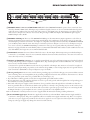
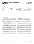
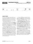
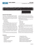
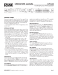
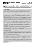
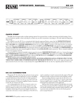
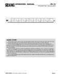
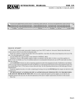
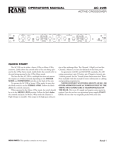
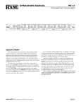
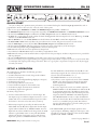
OPERATORS MANUAL
DA 26
DISTRIBUTION AMPLIFIER
PRIORITY
GAIN
DETECT
DUCKER
TARGET
LEVEL
CROSSOVER
AGC
OUTPUTS
1
RATIO
2
3
4
5
6
DA 26
FREQUENCY
MIN MAX
OL
ON +4
dBu
-80
ACTIVE
dB
0
-12 +12
dBu
1:1
GAIN
∞ :1
SLOW
FAST
-12 -6
-3
0
-12
3
6
12
80 110
150 200
+12
FULL HIGH LOW
-12
+12
FULL HIGH LOW
-12
+12
FULL HIGH LOW
-12
-12
+12
FULL HIGH LOW
+12
FULL HIGH LOW
-12
DISTRIBUTION
PROCESSOR
+12
FULL HIGH LOW
POWER
QUICK START
Are you in a hurry? For optimum system performance, we recommend reading the detailed Setup & Operation below and on
page Manual-4. For those who can’t wait, at least be aware of these points:
• There are two inputs: PRIORITY and LINE. The PRIORITY Input accepts MIC or LINE level.
• The PRIORITY Input sums with an output when assigned by the PRIORITY ASSIGN Port, and PRIORITY DETECT is active.
• The level of the PRIORITY Input is unaffected by the AGC, Output Level controls or Remote Level controls.
• The AGC only operates when the signal is within 26 dB of the Target Level. If the Line Input level is out of AGC range, the 0 dB
indicator on the AGC GAIN meter is off.
• With the RATIO set to ∞:1, the AGC GAIN meter should indicate about 0 dB for nominal Line Input levels.
• The AGC SLOW / FAST switch only affects the gain reduction time constant. The gain increase time constant is fixed.
• Only the LINE Input is processed by the AGC, CROSSOVER, Output Level and Remote level controls.
• The three Crossover Outputs (full-range, high-pass and low-pass) may be selected by any of the six Outputs.
• Set the initial Output levels using the Output Level controls on the front panel.
• Remote Level controls allow end user adjustment of Output level.
• Any combination of Remote Ports may be controlled by a single Remote device.
• Remote Level controls provide automatic loudness compensation for low-pass Outputs. Loudness compensation is not provided for
full range Outputs.
• The optional VR 1 Remote Level control provides audio taper control over a range of 0 dB to –80 dB.
• Never connect anything except an approved Rane power supply to the Input that looks like a telephone jack on the rear of the DA 26. This
is an AC Input and requires specific voltage and current. This is not a good place to experiment or improvise. Use only the supply
sent with your DA 26.
SETUP & OPERATION
The outline below is detailed in the following procedure.
1. Set Line Input level
2. Set AGC (Automatic Gain Control) Target Level and Ratio
3. Set Crossover frequency
4. Select Source for each Output (Full-range, High-pass or Low-pass)
5. Set Output Level controls
6. Connect Output Remote Level controls
7. Connect the Priority Input for the intended source
8. Set the Priority Input automatic Detect threshold
9. Set Ducking depth for the application
10. Priority Assign selection
1. Connect a balanced line level source to the Line Input. The
Line Input accepts an unbalanced Input connected to (+) and
(GND). We do not recommend unbalanced operation unless
the distance to the source is less than 3 feet [one meter].
2. The Line Input signal is processed by the AGC circuit. The
AGC GAIN meter 0 dB indicator lights when the Line Input
signal is within 26 dB of the set TARGET LEVEL. For Line
Input levels more than 26 dB below the Target Level, the 0 dB
indicator is off and AGC returns to unity. The AGC GAIN
indicates the amount of attenuation used to make the Line
Input level equal the set TARGET LEVEL. For best results,
WEAR PARTS: This product contains no wear parts.
the AGC GAIN meter should indicate about 0 dB for nominal Line Input signals. The best resolution for this adjustment is
achieved with the AGC RATIO set to ∞:1.
The TARGET LEVEL is set in one of two ways:
a) If you have a source output level control, set the TARGET
LEVEL to the desired setting and adjust the Line Input
level so that the AGC GAIN meter indicates 0 dB for
nominal signal levels.
b) If a source output level control is not available, adjust the
TARGET LEVEL so the AGC GAIN meter indicates 0 dB
for nominal Line Input levels. The difference between the
resulting AGC Target Level and the desired Target Level is
compensated with the OUTPUT trims. With Input level
and TARGET LEVEL correctly set, adjust the AGC RATIO to the desired value. We recommended values between
2:1 and ∞:1 as marked by the gray band. The soft-kneeresponse of the AGC results in a natural sounding response
with AGC Ratios as high as ∞:1.
3. The CROSSOVER splits the Line Input signal into three
separate Outputs: Full-Range, High-pass and Low-pass, each
selectable for each of the six Outputs. Select the desired FREQUENCY (80, 110,150 or 200 Hz).
continued on page Manual-4...
Manual-1
FRONT PANEL DESCRIPTION
PRIORITY
GAIN
DETECT
DUCKER
TARGET
LEVEL
CROSSOVER
AGC
OUTPUTS
1
RATIO
2
3
4
5
6
DA 26
FREQUENCY
MIN MAX
OL
ON +4
dBu
-80
ACTIVE
dB
0
-12 +12
dBu
1:1
GAIN
∞ :1
SLOW
FAST
-12 -6
-3
0
-12
3
6
12
80 110
150 200
+12
FULL HIGH LOW
-12
+12
FULL HIGH LOW
-12
+12
FULL HIGH LOW
-12
+12
FULL HIGH LOW
-12
+12
FULL HIGH LOW
-12
DISTRIBUTION
PROCESSOR
+12
FULL HIGH LOW
POWER
1 PRIORITY GAIN trim and OL indicator: adjusts the gain for the PRIORITY INPUT. Set this trim to prevent overloading the
Input — if the Priority Gain OL illuminates, turn down the GAIN.
2 PRIORITY DETECT trim and ACTIVE indicator: sets the threshold in dBu for the PRIORITY INPUT to override the LINE
INPUT. When the threshold has been reached, the ACTIVE indicator illuminates. Set the GAIN(1), then set the DETECT trim.
The range of operation is +4 dBu to ON. The release time for the auto-detect circuit is fixed at about 6 seconds, after which the
LINE INPUT signal returns to it's previous level.
3 PRIORITY DUCKER trim: sets the amount of attenuation applied to the LINE INPUT signal when the PRIORITY INPUT is
activated by the DETECT threshold. DUCKER depth is continuously adjustable over a range of 0 dB to –80 dB. For equal mixing of PRIORITY and LINE, set the DUCKER to 0 dB. For PRIORITY replaces LINE operation, use –80 dB. A value of –12
dB (1 o’clock) is typical for PRIORITY (page) talks over LINE (music) operation.
4 AGC TARGET LEVEL trim: is best set so the average signal at the LINE INPUT reads 0 dB on the GAIN meter. This gives the
best performance of the AGC (Automatic Gain Control). Active constant gain range of the AGC is ±12 dB (24 dB range). When
the Input falls 26 dB below the AGC Target Level, gain returns to unity. See Setup and Operation, step 2.
5 AGC RATIO trim: determines the Ratio applied to the AGC with a soft-knee response. Increased clockwise rotation increases
the amount of AGC. The full counter-clockwise position disables the AGC. The normal range of operation is between 2:1 and
∞:1 as marked by the gray band.
6 AGC SLOW/FAST release switch: determines the gain reduction time constant of the AGC circuit. SLOW = 230 ms (best for
music), FAST = 11 ms (best for voice). The gain increase time constant is fixed at 1100 ms.
7 AGC GAIN meter: indicates the amount of AGC applied to the LINE INPUT. The 0 dB GAIN indicator is off if the Input is
more than 26 dB below the Target Level.
8 CROSSOVER FREQUENCY switch and indicators: select the FREQUENCY for the 2-way Crossover when High-Pass and/or
Low-Pass outputs are used (80, 110,150 or 200 Hz). High, Low or Full-Range is selectable for each of the six Outputs.
9 OUTPUT trims and Crossover select switches: The ±12 dB trims set the levels for each of the six Outputs. High, Low or
Full-Range is switch selectable for each of the six Outputs. Note: the Output trims do not affect Low-pass loudness compensation or
Priority Input level. See Setup & Operation, step 5.
0 POWER indicator LED: This yellow illumination device lights up to let the operator know the thing is plugged in.
Manual-2
REAR PANEL DESCRIPTION
DA 26
POWER
MADE IN U.S.A.
RANE CORP.
ACN 001 345 482
600mA
CLASS 2 EQUIPMENT
RMT
6
OUT
RMT
5
OUT
RMT
4
OUT
RMT
3
OUT
RMT
2
OUT
RMT
1
OUT
LINE
INPUT
PRIORITY
ASSIGN
Vr Vc
+
-
Vr Vc
+
-
Vr Vc
+
-
Vr Vc
+
-
Vr Vc
+
-
Vr Vc
+
-
+
-
Z1 Z2 Z3 Z4 Z5 Z6 ALL
Vr Vc
+
-
Vr Vc
+
-
Vr Vc
+
-
Vr Vc
+
-
Vr Vc
+
-
Vr Vc
+
-
+
-
Z1 Z2 Z3 Z4 Z5 Z6 ALL
PRIORITY
INPUT
LINE
MIC
+
-
+
-
1 PRIORITY INPUT connector and MIC/LINE switch: The balanced PRIORITY INPUT operates at line or mic level, determined by the MIC / LINE switch. This Input accepts unbalanced signals, however, we do not recommend unbalanced operation
unless the source is within 3 feet [one meter]; then only connect (+) and (GND). Note: the Priority Input is not influenced by the
AGC, Crossover, Output trims or Remote Level controls. The gain range for MIC level Input is 30 to 60 dB. The gain range for
LINE level Input is 0 to 30 dB.
2 PRIORITY ASSIGN port: The state of the PRIORITY ASSIGN port determines Priority Input assignment to each of the six
Outputs. Assignment pins are active low with passive internal pull-up. Any combination of pins may be active at one time. The
select ALL pin is provided for convenience. To complete an assignment, the Output must be selected by the PRIORITY ASSIGN
port and Priority Detect must be active. Note that if a combination of Crossover Outputs is used in one zone, all Outputs serving the
zone must be selected by the PRIORITY ASSIGN port. Variations in wire type do not greatly affect the performance of this port.
However, 22-gauge stranded wire with a flexible jacket is recommended. Unshielded multi-conductor cable is OK for shorter runs
(less than 100 feet). For longer runs, we recommend shielded cable.
3 LINE INPUT connector: Connect a balanced line level source to the Line Input. The Line Input accepts an unbalanced Input
connected to (+) and (GND), but we do not recommend unbalanced connection unless the distance to the source is less than one
meter; then only connect (+) and (GND).
4 OUTPUT and REMOTE connectors: are on single 6-pin Euroblocks, one set for each Output. Outputs are line-level, balanced,
and hopefully driving a balanced equalizer or amplifier. If not, keep cable lengths short and consult RaneNote 110, “Sound System
Interconnection” located elsewhere in this manual.
Connections for optional wired Remote Level controls are provided for each Output. Note: Remote Level controls do not affect the
level of the Priority Input. Each port provides a 5 volt reference voltage (REF), a control voltage input (Vc) and a ground reference.
Gain control law is 50 mV/dB. See Setup and Operation, step 6 for details.
5 Chassis ground point: A #6-32 screw is used for chassis grounding purposes. If after hooking up your system it exhibits excessive
hum or buzzing, there is an incompatibility in the grounding configuration between units somewhere. Your mission is to discover
how your particular system wants to be grounded. Here are some things to try:
1. Try combinations of lifting grounds on units that are supplied with ground lift switches or links.
2. If your equipment is in a rack, verify that all chassis are tied to a good earth ground, either through the line cord grounding pin or
the rack screws to another grounded chassis.
3. Units with outboard power supplies, such as the DA 26, do not ground the chassis through the line cord. Make sure that these
units are grounded either to another chassis which is earth grounded, or directly to the grounding screw on an AC outlet cover by
means of a wire connected to a screw on the chassis with a star washer to guarantee proper contact. If you are connecting the DA
26 Outputs directly to a power amplifier, be sure to connect a ground wire to the amplifier chassis.
Refer to the RaneNote “Sound System Interconnection” (supplied with this manual) for further grounding information.
6 Remote POWER supply input: The DA 26 is supplied from the factory with a Model RS 1 Remote Power Supply suitable for
connection to this input jack. The power requirements call for an 18 VAC center-tapped transformer only. This is not a telephone
jack. Never use a power supply with your DA 26 other than the one supplied or an exact replacement obtained from Rane Corporation.
Using any other type of supply may damage the unit and void the warranty.
Manual-3
Setup & Operation…continued from page Manual-1...
4. Next, set up the six OUTPUTS. First, determine the number of zones served and the signals to be sent to each. Using
a drawing like the example application diagram in the Data
Sheet is helpful. For ease of wiring, make Outputs serving a
common zone adjacent. Select Full-range, High-pass or Lowpass as required for each output. The following are possible
zone configurations:
• Full-range only for medium size bookshelf speakers.
• High-pass only for small distributed ceiling speakers.
• Full-range output combined with Low-pass Output to enhance bass response.
• High-pass output combined with Low-pass Output for true
bi-amp operation.
5. The ±12 dB OUTPUT trims set Output levels, with relative
levels between Full-range, High-pass and Low-pass. Note: the
Output trims do not affect Low-pass loudness compensation or
Priority Input level. The idea is to set system levels for proper
operation at the maximum required SPL (with Remote Level
controls set for unity gain). Remote Level controls then attenuate the level as required.
Automatic loudness compensation is achieved by altering the gain control law of any Remote port associated with
a Low-pass Output. A Low-pass Output is always used in
conjunction with a high-pass or full-range Output. Because
the Remote Level control turns the low-pass Output down
at a lesser rate than the high-pass or full-range Output, bass
response is enhanced. The corner frequency for loudness compensation is set by the CROSSOVER frequency selection. The
reference level for the room is set with the OUTPUT trim
on the front panel. Any Remote Level gain change results in
automatic loudness compensation.
6. A port for a wired Remote Level control is provided for each
Output. Note: Remote Level controls do not affect the level of the
Priority Input. Each port provides a 5 volt reference voltage
(REF), a control voltage input (Vc) and a ground reference.
The gain control law for Vc is 50 mV/dB. Using the optional
VR 1 Remote control provides an audio taper response from
0 dB to > -80 dB. To control more than one Remote Port with
a single Remote control, it is only necessary to connect the Vc pin
of each additional port. An external ground referenced control
voltage with a range of 0 to 5 volts may be used with the
Remote ports. If the ratiometric output of a linear potentiometer is used, (GND to CW, Vc to center tap, REF to CCW),
a linear log response results. Audio taper response requires a
potentiometer with a reverse log taper. Audio taper response is
achievable using a linear potentiometer by connecting a resistor equal to 1/10th the value of the potentiometer between
GND and Vc as shown below:
cw
10k
1k
GND
Vc
Variations in wire type do not greatly affect the performance
of the Remote controls. However, 22-gauge stranded wire
with a flexible jacket is recommended. You may use 3-conductor unshielded remote control signal cable for shorter
runs (less than 100 feet [30 meters]). For longer runs, we
recommend using shielded cable. The type of wire required
is influenced by your installation and local electrical codes.
Rane Corporation does not provide cable— please contact
your local retail or wholesale outlet.
7. The balanced PRIORITY INPUT operates at line or mic level,
determined by the MIC / LINE switch, on the rear panel
next to the PRIORITY INPUT jack. See Rear Panel (1) for
unbalanced connection rules. Note: the Priority Input is not
influenced by the AGC, Crossover, Output trims or Remote Level
controls. The gain range for MIC level Input is 30 to 60 dB.
The gain range for LINE level Input is 0 to 30 dB. Set the
PRIORITY GAIN to prevent overloading the Input — if the
Priority Gain OL illuminates, turn down the GAIN.
8. The PRIORITY DETECT threshold is calibrated in dBu,
and monitors the signal after the input preamp. Any change
in PRIORITY GAIN setting affects the DETECT sensitivity. Set the GAIN, then set DETECT. The range of operation
is +4 dBu to ON. The consequence of setting DETECT too
low is premature triggering due to background noise. Setting
DETECT too high results in excess delay and a sudden large
step in amplitude (perceived as a “pop”). If a paging mic is
used in an environment with a lot of background noise, we
recommend a push-to-talk device.
The release time is fixed at about 6 seconds. The release delay
is based on the typical time required to accommodate a pause
in speech or dead-time between music programs.
9. The PRIORITY DUCKER depth sets the amount of attenuation applied to the LINE INPUT signal when the
PRIORITY INPUT is activated by the DETECT threshold.
DUCKER depth is continuously adjustable over a range of 0
dB to -80 dB. For equal mixing of PRIORITY and LINE, set
the DUCKER to 0 dB. For PRIORITY replaces LINE operation, use –80 dB. A value of –12 dB (2 o’clock) is typical for
PRIORITY (page) talks over LINE (music) operation.
10. The state of the PRIORITY ASSIGN port determines Priority Input assignment to each of the six Outputs. Assignment
pins are active low with passive internal pull-up. Any combination of pins may be active at one time. The select ALL pin
is provided for convenience. To complete an assignment, the
Output must be selected by the PRIORITY ASSIGN port
and Priority Detect must be active. Note that if a combination
of Crossover Outputs is used in one zone, all Outputs serving the
zone must be selected by the PRIORITY ASSIGN port. The type
of wire recommended is similar to the description in Step 6
above.
REF
©Rane Corporation 10802 47th Ave. W., Mukilteo WA 98275-5098 TEL 425-355-6000 FAX 425-347-7757 WEB www.rane.com
Manual-4
104699