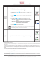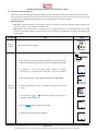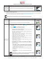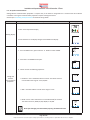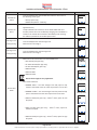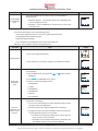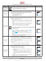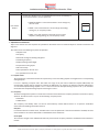
1
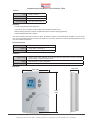
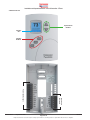
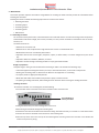
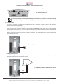
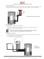
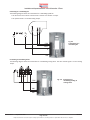
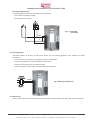
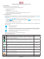
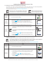
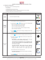
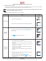
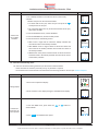
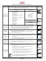
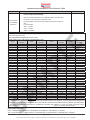
Fan Coil Controller – EZstat
www.Engineered-Comfort.com
Date: 9-2014
Supersedes: NEW
Page 1 of 36
Engineered Comfort reserves the right to change any information concerning product or specification without notice or obligation.
EC-EZstat
Installation and Operation Manual ● Fan Coil Controller – EZstat
CONTENTS
1
P REFACE.....................................................................................................................................3
2SAFETY SYMBOLS & CONSIDERATIONS....................................................................................3
3
I NTRODUCTION.........................................................................................................................3
3.1 FEATURES.................................................................................................................................. 3
3.2 USER FUNCTIONS..................................................................................................................... 3
3.3 SPECIFICATIONS....................................................................................................................... 4
3.4 EZSTAT FEATURES..................................................................................................................... 6
4
I NSTALLATION............................................................................................................................7
4.1 MOUNTING THE EZSTAT.......................................................................................................... 7
4.2 CONNECTING INPUTS.............................................................................................................. 8
4.3 CONNECTING OUTPUTS.......................................................................................................... 9
4.4 CONNECTING POWER............................................................................................................ 11
4.5 MAINTENANCE....................................................................................................................... 11
5
U SER FUNCTIONS....................................................................................................................12
5.1 OPERATING THE EZSTAT........................................................................................................ 12
5.2 ENTERING USER OR ADMIN PASSWORD............................................................................. 13
5.3 CHANGING THE ACTIVE SETPOINTS..................................................................................... 13
5.4 SETTING THE OPERATING MODES........................................................................................ 14
6
C OMMISSIONING FUNCTIONS................................................................................................15
6.1 CREATING AND/OR CHANGING PASSWORDS...................................................................... 16
6.2 SETTING THE COMMISSIONING SETPOINTS....................................................................... 17
6.3 SET UP THE COMMUNICATIONS........................................................................................... 18
6.4 SET THE TIME AND DATE....................................................................................................... 19
6.5 SETTING THE OCCUPANCY SCHEDULE................................................................................. 20
6.6 ENTER THE COMMISSIONING MODE................................................................................... 21
6.7 ADVANCED OPTIONS............................................................................................................. 25
7SEQUENCES OF OPERATION....................................................................................................27
7.1 SETPOINT LIMITS................................................................................................................... 27
7.2 OCCUPANCY............................................................................................................................ 27
7.3 AUTOMATIC COOLING AND HEATING CHANGEOVER......................................................... 28
7.4 SCHEDULING OCCUPANCY.................................................................................................... 28
7.5 DISPLAY BLANKING AND BACKLIGHT................................................................................... 28
7.6 TEMPERATURE SENSING INPUTS.......................................................................................... 28
7.7 PID CONTROL LOOPS............................................................................................................. 28
7.8 VALVE OPERATION FOR FAN COILS....................................................................................... 28
7.9 FAN OPERATION FOR FAN COILS.......................................................................................... 29
7.10 ONE, TWO, AND THREE SPEED FANS.................................................................................... 29
8
SYSTEM INTEGRATION............................................................................................................30
8.1 BACNET OBJECTS................................................................................................................... 30
8.2 CONNECTING TO MS/TP NETWORK..................................................................................... 34
Date: 9-2014
Supersedes: NEW
Page 2 of 36
Engineered Comfort reserves the right to change any information concerning product or specification without notice or obligation.
EC-EZstat
Installation and Operation Manual ● Fan Coil Controller – EZstat
1PREFACE
Your equipment is initially protected under the manufacturer’s standard warranty. However, this warranty is provided under the
condition that the steps outlined in this manual are followed for initial inspection, proper installation, periodic maintenance and
everyday operation of the equipment.
This manual should be fully reviewed in advance of any actual work being done on the equipment. Should any questions
arise, please contact your local Sales Representative or the factory before proceeding.
Consult the approved unit submittal, order acknowledgment, and other manuals for details on the applications and accessories
provided with the equipment on each project.
Always follow proper procedures related to safety, handling, installation, operation, servicing of mechanical equipment as the
manufacturer assumes no responsibility for personal injury or property damage resulting from improper or unsafe practices
during handling, service or operation of any equipment.
2 SAFETY SYMBOLS & CONSIDERATIONS
The equipment covered by this manual is designed for safe and reliable operation within its design specification limits. To avoid
personal injury or damage to equipment or property while installing or operating this equipment, it is essential that qualified,
experienced personnel perform these functions using good judgment and safe practices. To promote safety, the following
symbols are used in this document to alert the reader to potential hazards:
DANGER indicates an imminently hazardous
situation which, if not avoided, will result in
death or serious injury.
CAUTION identifies a hazard which could lead
to damage to the machine, damage to other
equipment and/or environmental pollution.
Usually an instruction will be given, together
with a brief explanation.
NOTE
T IP
NOTE is used to highlight additional information
which may be helpful to you.
TIP indicates time saving shortcuts and
programming tips.
WARNING indicates a potentially hazardous
situation which, if not avoided, could result in
death or serious injury.
3INTRODUCTION
The EZstat combines the power of a space‑mounted equipment controller with the convenience of built-in temperature sensors.
The EZstat controller includes a wide range of factory supplied programs for two and four pipe fan coil units.
3.1Features
• No special programming, software application, or setup tools are required to configure and commission an
EZstat
• Bright, full-color display is easy to read across a room even in bright sunlight
• Display - Large numbers and simple color icons to indicate heating or cooling, local setback modes, and fan operation
• Five function keys, operator can change set-points and fan, heating, cooling modes, choose between Fahrenheit or
Celsius values, Set BACnet addressing, Set up and commission the installation, and add or change user passwords
• Ready to connect to a BACnet MS/TP network. Device instance, MAC address, and baud rate are set from the
password protected front controls; feature a hardware clock and BACnet schedule that can be set up from the front
panel or as standard BACnet objects and properties
• White finish
3.2 User Functions
EZstat user functions are limited to changing the following functions:
• Active temperature set-points
• Fan operation
• Changing between heating and cooling
• Override scheduled occupancy or occupancy based on the schedule in the EZstat
• Change the display between Fahrenheit and Celsius
Date: 9-2014
Supersedes: NEW
Page 3 of 36
Engineered Comfort reserves the right to change any information concerning product or specification without notice or obligation.
EC-EZstat
Installation and Operation Manual ● Fan Coil Controller – EZstat
3.3 Specifications
EZstat specifications are subject to change without notice.
User Interface
The user interface is a color display and with five push buttons. Through the menu driven display, an operator can do the
following:
• Add or change user passwords
• Change setpoints
• Set BACnet addressing
• Set up and commission the installation
• Configure any available options
Security
Separate passwords for users and controls technicians.
Display type
• 128 ×128 pixels
• Active color LCD with LED back lighting
• 0.98 x 1.04 inches (25 x 26 mm)
Inputs and outputs
All inputs and outputs are preprogrammed and application specific. Review wiring label for proper connections.
Analog inputs
Analog inputs represent BACnet analog input objects and are configured for discharge air temperature, remote
temperature sensor and water temperature sensor. Not all input sensors are applicable or required for all applications.
• Sensors are automatically detected
• Inputs accept industry-standard 10,000 Ω, Type II (Nailor Part# H1-1989) or Type III (Nailor Part# H1-0246 and H1-1764B)
thermistors sensors.
• Input overvoltage protection up to 24 VAC, continuous. 12-bit analog-to-digital conversion
Analog outputs
Analog outputs are configured to represent BACnet analog objects. The outputs control modulating valves, and variable
speed fans, or other equipment that requires a proportional input signal.
• Short-circuit protected
• Loads up to 10 mA at 0–12 VDC
• 8-bit PWM digital-to-analog conversion
Relay outputs
Relay outputs are configured to represent BACnet binary objects. The outputs control On/Off valves, speeds for threespeed fans, fan start circuits, or electric heat.
• All relay outputs are normally open, SPST, Form “A” relays
• 1 ampere maximum per relay at 24 VAC or VDC for each output. Maximum for all relay outputs is 3 amperes (72VA).
Connectors
• Screw terminal block mounted to back plate
• Wire size 14-22 AWG
Communications—BACnet MS/TP
• Integral peer-to-peer BACnet MS/TP network communications. Network speeds from 9600 to 76,800 baud.
• Front panel configurable device instance, MAC address, and baud. Automatic baud detection, see the topic Set up the
communication. Screw terminal block mounted to back-plate. Wire size 14–22 AWG
• Meets or exceeds ANSI/ASHRAE BACnet Standard 135-2008 for Application Specific Controllers
Date: 9-2014
Supersedes: NEW
Page 4 of 36
Engineered Comfort reserves the right to change any information concerning product or specification without notice or obligation.
EC-EZstat
Installation and Operation Manual ● Fan Coil Controller – EZstat
Accuracy
Type
±0.36° F (±0.2° C)
Accuracy
±0.36° F (±0.2° C)
Resistance
Operating Range
10,000 Ω at 77° F (25° C)
48 to 96° F (8.8 to 35.5° C)
Regulatory
• UL 916 Energy Management Equipment
• FCC Class A, Part 15, Subpart B and complies with Canadian ICES-003 Class B
• BACnet Testing Laboratory listed as an application specific controller (listing applied for)
• SASO PCP Registration KSA R-103263
This device complies with part 15 of the FCC Rules. Operation is subject to the following two conditions: (1) This device
may not cause harmful interference, and (2) this device must accept any interference received, including interference that
may cause undesired operation.
Environmental limits
Operating
32 to 120° F (0 to 49° C)
Shipping
–40 to 140° F (–40 to 60° C)
Humidity
0–95% relative humidity (non-condensing
Installation
Supply Voltage
Weight
Case Material
24 VAC (–15%, +20%), 50-60 Hz, 12 VA, Class 2 only, non-supervised. All circuits, including
supply voltage, are power limited circuits.
Approximately 6 ounces (170 grams)
Flame retardant plastic
Dimensions
1 1/8” (29)
3 1/2” (89)
5 1/8”
(130)
Date: 9-2014
Supersedes: NEW
Page 5 of 36
Engineered Comfort reserves the right to change any information concerning product or specification without notice or obligation.
EC-EZstat
Installation and Operation Manual ● Fan Coil Controller – EZstat
3.4 EZstat Features
Up and Down
Buttons
Soft Key
Bar
Soft Key
Buttons
Supersedes: NEW
Inputs and
Network
Power and Outputs
Date: 9-2014
Page 6 of 36
Engineered Comfort reserves the right to change any information concerning product or specification without notice or obligation.
EC-EZstat
Installation and Operation Manual ● Fan Coil Controller – EZstat
4INSTALLATION
This section provides important instructions and guidelines for installing the EZstat. Carefully review this information before
installing the controllers.
Installing the sensors includes the following topics that are covered in this section:
• Mounting the EZstat
• Connecting inputs
• Connecting outputs
• Connecting power
• Maintenance
4.1 Mounting the EZstat
For the most accurate performance, install the EZstat on an inside wall where it can sense the average room temperature.
Avoid locations with direct sunlight, heat sources, windows, air vents, and air circulation or obstructions such as curtains,
furniture, etc.
The EZstat must not be:
• Mounted on an exterior wall.
• Mounted on or near an object with a large thermal mass such as a concrete block wall.
• Blocked from normal air circulation by obstructions.
• Exposed to heat sources such as lights, computers, copiers, or coffee makers, or to direct sunlight at any time of the
day.
• Exposed to drafts from windows, diffusers, or returns.
• Exposed to air flow through connecting conduits or empty spaces behind walls.
Rough-in preparation
Complete rough-in wiring at each location before mounting an EZstat. This includes the following steps
• Install the supplied mounting base directly to a wall, a vertical electrical box, or a box with a wall plate kit.
• Routing the connecting cable or cables from the EZstat to the equipment it is controlling.
• If required, install an appropriate wall plate kit.
• Block leaks and airflow from conduits with plumber’s putty or similar material.
• If replacing an existing thermostat, label existing wires for reference when removing the existing thermostat.
Installing the EZstat
To install the controller on a mounting base, do the following:
1.Turn the Allen screw in the base of the sensor clockwise until it clears the case.
Turn Clockwise to
remove from base
2.Swing the EZstat away from the mounting base to remove it.
3.Route wiring for the EZstat through the mounting base.
4.Position the base with the embossed UP toward the ceiling and fasten it directly to a vertical 2 x 4 inch electrical box.
5.Connect the wires for the EZstat to the terminals in the mounting base.
6.Place the top of the sensor over the top of the mounting base and swing it down over the Allen screw bracket. Be
careful not to pinch any wiring.
Date: 9-2014
Supersedes: NEW
Page 7 of 36
Engineered Comfort reserves the right to change any information concerning product or specification without notice or obligation.
EC-EZstat
Installation and Operation Manual ● Fan Coil Controller – EZstat
7. Turn the Allen screw counterclockwise until it backs out of the mounting base and engages the case.
Turn Counterclockwise until
the screw engages the base.
To prevent mounting screw heads from toughing the circuit board in the controller, use only the mounting
screws supplied. Using screws other than the type supplied may damage the EZstat unit.
4.2 Connecting Inputs
The inputs for the EZstat are configured for specific functions and do not require set up in the field. Not all inputs are
required for every model or application.
Remote space temperature sensor (optional)
Connect a 10kΩ, Type II thermistor temperature sensor (Nailor part #H1-1989) to the remote space temperature (RS)
input and ground (GND) terminals. The input includes the internal pull-up resistor. Follow the instructions supplied with
the sensor for installation.
When a remote space temperature input is connected to the EZstat, the remote temperature is used instead of the
internal temperature sensor.
Fig. 4-1 Wiring for remote space temperature sensor
RS
GRD
Discharge air temperature
Connect a 10kΩ, Type III thermistor temperature (Nailor part #H1-0246) probe to the discharge air temperature (DAT)
input. The input includes the internal pull-up resistor.
Fig. 4-2 Wiring for Discharge Air Temperature Sensor
GND
DAT
Date: 9-2014
Supersedes: NEW
Page 8 of 36
Engineered Comfort reserves the right to change any information concerning product or specification without notice or obligation.
EC-EZstat
Installation and Operation Manual ● Fan Coil Controller – EZstat
Water temperature sensor
Connect a 10kΩ, Type III thermistor temperature probe (Nailor part #H1-1764B) to the water temperature (WST) input.
The input includes the internal pull-up resistor. Follow the instructions supplied with the sensor for installation.
Fig. 4-3 Wiring for a water temperature sensor
WST
GND
4.3 Connecting Outputs
The EZstat outputs are configured for specific applications.
• Depending on the configuration, the EZstat outputs are designed for either 24 VAC or 0-10 VDC loads.
• The outputs may represent analog or digital signals.
Improperly connecting loads or equipment to output terminals may damage the equipment.
Connect only as shown in the following diagrams or application drawings.
Connecting to a three-speed fan
The following diagram shows the connections for a three-speed fan. The fan circuits must be a 24 VAC pilot duty only.
• For a single-speed fan, use only the FAN-L connection.
FAN-H
FAN-M
FAN-L
• For a three-speed, use FAN-L, FAN-M, and FAN-H
COM
Fig. 4-4
Connections to a
three-speed fan
R
Date: 9-2014
Supersedes: NEW
Page 9 of 36
Engineered Comfort reserves the right to change any information concerning product or specification without notice or obligation.
EC-EZstat
Installation and Operation Manual ● Fan Coil Controller – EZstat
Connecting to a modulating fan
The following diagram shows the connections for a modulating speed fan.
• The fan start circuit must be a 24 VAC circuit. Connect it to the FAN- L output.
• The speed control is a 0-10 VDC analog output.
COM
FAN-L
Fig. 4-5
Connections for a
modulating fan
R
A08
Connecting to modulating valves
The following diagram shows the connections for a modulating mixing valves. The valve control signal is a 0-10 V analog
output.
Fig. 4-6 Connections to
modulating heating &
cooling valves
COM
A06
A07
Date: 9-2014
Supersedes: NEW
Page 10 of 36
Engineered Comfort reserves the right to change any information concerning product or specification without notice or obligation.
EC-EZstat
Installation and Operation Manual ● Fan Coil Controller – EZstat
Connecting to On/Off valves
The following diagram shows the connections for an on/off valve.
• The valves are actuated by 24 VAC
• The outputs are 24 V relays.
Fig. 4-7 Connecting
on/off valve
COM
R
B05
4.4 Connecting Power
The EZstat requires an external, 24 VAC power source. Use the following guidelines when choosing and wiring
transformers.
• Use only a Class-2 transformer of the appropriate size to supply power.
• Connect the transformer’s neutral lead to the COM terminal.
• Connect the AC phase lead to the 24VAC terminal.
• Power is applied to the controller when the transformer is powered.
24VAC
Fig. 4-8 Wiring for EZstat power
COM
4.5Maintenance
Remove dust as necessary from the holes in the top and bottom. Clean the display with soft, damp cloth and mild soap.
Date: 9-2014
Supersedes: NEW
Page 11 of 36
Engineered Comfort reserves the right to change any information concerning product or specification without notice or obligation.
EC-EZstat
Installation and Operation Manual ● Fan Coil Controller – EZstat
5 USER FUNCTIONS
This section covers topics for the end user in a facility.
EZstat user functions are limited to changing the following functions:
• Active temperature setpoints
• Fan operation
• Changing between heating and cooling
• Override scheduled occupancy or occupancy based on the schedule in the EZstat.
• Change the display between Fahrenheit and Celsius
5.1 Operating the EZstat
EZstat functions are accessible through a user interface consisting of simple, context sensitive menus. The menus are
opened and options are selected by using the buttons and a color display on the front of the EZstat. See Section 3.4 for
EZstat features.
• Pressing either the
or
button changes a selection, setting, or value.
• Pressing the Enter button saves the selected setting or value. Typically the Enter button is the middle of the three
buttons below the display.
• Saving a selection also advances to the next display.
The three buttons below the display are defined by labels in the soft key bar. Typically the buttons are designated for the
following functions:
Back
Returns to the previous menu.
Cncl
Cancels current changes.
Done
Push this button at any point while entering a value. For example, if you have entered the first two digits of
a password and the remaining two digits are correct, pushing Done completes the entry of the password.
Enter
Pushing this button enters the selection and advances to the next step.
Exit
Returns to temperature display
The operating modes of the EZstat are represented by the display icons.
Table 5–1 Operating mode icons
Icon
Description
Mode
The fan icon rotates when the system fan is operational. In systems with multispeed fans the
icon rotation is the same regardless of speed. When fan operation is set to automatic, the
word “ON” is placed under the fan icon.
Off
Date: 9-2014
Fan
Occupied—Occupancy is set to occupied by the schedule maintained in the controller.
Occupancy
Unoccupied—Occupancy is set to unoccupied by the schedule maintained in the controller.
Occupancy
Standby—The space is temporarily unoccupied because of lack of detected motion in the
room.
Occupancy
Override—A user has entered temperature setpoints that override the unoccupied setpoints.
Occupancy
Cooling—The system will cool the space until the cooling setpoint is reach. The icon is in
motion when cooling is taking place.
Heating/Cooling
Heating—The system will heat the space until the heating setpoint is reached. The icon is in
motion when heating is taking place.
Heating/Cooling
System is off
Heating/Cooling
Supersedes: NEW
Page 12 of 36
Engineered Comfort reserves the right to change any information concerning product or specification without notice or obligation.
EC-EZstat
Installation and Operation Manual ● Fan Coil Controller – EZstat
5.2 Entering User or Admin Password (Password 1 & 2, respectively)
User functions may require a password consisting of four numbers. Once either the User or Admin level password is
entered, the functions will remain unlocked for 60-seconds after the last button is pushed.
To set up the password levels, go to Create and/or change Passwords.
Security User Level – Calls up Password 1 in the program
NOTE
Security Admin Level – Calls up Password 2 in the program.
Procedure
T IP
Allow 60 seconds time elapse for
password change/setup to enable.
Steps
Starting
Display
Display
70
Start at the temperature display.
AUTO
1. Press either the
or
button for the first digit of Password 1.
2. Press the Enter button to select the next digit. Repeat for all
remaining digits. The Enter button is the middle of the three buttons
below the display.
Enter
the User
Password
°F
AUTO
SECURITY
USER LEVEL
0000
Enter
If the password is correct, the display will advance to the first menu.
1. Press the left and right buttons below the display at the same time
and hold them until the display changes to the SECURITY ADMIN
LEVEL Display
Enter the
Admin
Password
NOTE
If Password 2 has not previously been entered, the display will change to the
MAIN menu.
2. Press either the
or
SECURITY
ADMIN LEVEL
0000
button for the first digit of Password 2.
3. Press the Enter button to select the next digit. Repeat for all
remaining digits.
Enter
5.3 Changing the active setpoints
To enter or change the active temperature setpoints you may need to enter the User password.
NOTE
In the following procedure the current active setpoint–either cooling or heating–is the first setpoint to
change. Once that setpoint is entered, the display advances to the next setpoint.
To change the operation of the fan, occupancy, or heating/cooling, see the topic Setting the operating modes.
Procedure
Starting
Display
Steps
Display
70
Start at the temperature display.
AUTO
Enter the
Password
2. Press the button to save the value. The display will advance to the
next setpoint.
3. Press either the
or
Cncl
Supersedes: NEW
Enter
Done
72
°F
COOLING SETPT
Cncl
Date: 9-2014
°F
HEATING SETPT
button to change the setpoint.
4. Press the Enter button to save the value. The display will return to the
temperature display
AUTO
68
1. Press either the or button to change the active temperature setpoint.
°F
Page 13 of 36
Engineered Comfort reserves the right to change any information concerning product or specification without notice or obligation.
Enter
Done
EC-EZstat
Installation and Operation Manual ● Fan Coil Controller – EZstat
5.4 Setting the operating modes
The operating modes set the following functions:
• Fan operation
• Changing between heating and cooling
• Override scheduled occupancy or occupancy that has been set by a schedule.
• Change the display units from Fahrenheit to Celsius.
Procedure
Starting
Display
Steps
Display
70
Start at the temperature display.
AUTO
1. Push the button under the heating/cooling icon.
2. Press either the
or
button to select the heating/cooling
mode. The mode may be one of the following.
Change the
heating
or cooling
mode.
°F
AUTO
MODE: HEAT
COOL
AUTO
OFF
Cncl
Enter
• Heat—The system will only heat the space.
• Cool—The system will only cool the space.
• Auto—The system will switch between heating and cooling.
• Off—The system is turned off.
3. Press the Enter button to save the setting. The display returns to the
temperature display.
Heating/Cooling
Icons
1. Press the Enter button to select the next digit. Repeat for all four digits.
2. Press either the
following options.
or
button to select the fan mode from the
Fan Icon
• Auto (Default) — Auto function is utilized to match EPIC (ECM)
motor with this feature for optimum energy savings.
Set the fan
mode.
AUTO FAN RESET for ECM applications only, by enabling the AUTO
FAN RESET located in SYSTEM menu. To adjust default time of 60
mins, select LOCAL OVRD TIME. The AUTO FAN RESET and LOCAL
OVRD TIME work together.
Enter
The AUTO FAN RESET function protects from user accidentally
changing out of FAN - AUTO mode on interface. After time
expires, the control will reset back to Auto Mode, while
ensuring the efficiency benefits of the variable speed motor.
The word ON will be placed under the fan icon.
• Low, Med, High—Sets the speed at which 3-speed or modulating
fans will run continuously.
3. Press the Enter button to save the setting. The display returns to the
temperature display.
Date: 9-2014
AUTO FAN RESET
ENABLE
DISABLE
Supersedes: NEW
FAN: HIGH
MED
LOW
AUTO
Cncl
Enter
Multi-speed
fan option
Page 14 of 36
Engineered Comfort reserves the right to change any information concerning product or specification without notice or obligation.
EC-EZstat
Installation and Operation Manual ● Fan Coil Controller – EZstat
Procedure
Steps
Display
Entering an override setpoint can only take place if the EZstat is in the
unoccupied mode.
1. Push the button under the unoccupied icon
2. Press either the
password.
or
.
button to change the first digit of the
3. Press the Enter button to select the next digit. Repeat for all four
digits.
Change the
override
setpoint
4. Press either the
or
65
AUTO
°F
AUTO
button to turn the override on or off.
• Override Off—The controller uses the unoccupied setpoint as the active
setpoint.
LOCAL OVRD: ON
OFF
• Override On—the controller changes to the occupied setpoint
which can then be temporarily changed.
Cncl
Enter
5. Press the Enter button to save the setting.
NOTE
When the system is in the unoccupied mode, changing the active setpoint will
automatically place the system in the override mode.
70
Change the
display units
To temporarily change the display units to either Celsius or Fahrenheit,
press and hold the middle button under the display until the units change.
AUTO
AUTO
21
AUTO
°F
°C
.0
AUTO
6 COMMISSIONING FUNCTIONS
The topics in this section are advanced topics for control technicians and engineers. These topics cover procedures for the initial
EZstat setup.
The EZstat commissioning functions are values and settings that are entered during the installation and commissioning of a
controller and the equipment it is controlling. Typically these functions do not change after the installation and commissioning
process.
To set up the commissioning functions, you will need the following information:
• Information about the equipment
• The sequence of operation for the equipment
• The building automation system plans for controllers that are part of a network.
Users may change the occupied heating and cooling setpoints without accessing the commissioning functions. This procedure
is covered in the topic User functions.
Date: 9-2014
Supersedes: NEW
Page 15 of 36
Engineered Comfort reserves the right to change any information concerning product or specification without notice or obligation.
EC-EZstat
Installation and Operation Manual ● Fan Coil Controller – EZstat
6.1 Create and/or Change Passwords
For access to the commissioning functions you will need to know the Admin Level Password, also known as Password 2.
If the controller has not been previously set up, no password is required and the user can either continue on to setup the
User & Admin Level passwords (see table below) or proceed directly to the section of interest.
Password Functions:
• User Level – Calls up Password 1 in the program. This is for a facility user and limits changes to active setpoints, fan
operation, occupancy, and heating and cooling modes.
• Admin Level – Calls up Password 2 in the program. This is generally used by a controls technician to set up and
commission the EZstat. When set, will lock user out from setpoints, fan operation, occupancy, and heating and
cooling modes.
Procedure
Starting
Display
Steps
Display
70
Start at the temperature display.
AUTO
°F
AUTO
1. Press the left and right buttons below the display at the same time and
hold them until the display changes to the SECURITY ADMIN LEVEL display
SECURITY
ADMIN LEVEL
0000
2. If Password 2 has not previously been entered, the display
will change to the MAIN menu. Otherwise, enter the password.
3. Under the MAIN menu, select ADVANCED followed by PASSWORDS.
Enter
MAIN
SETPOINT
SCHEDULE
SYSTEM
COMM
ADVANCED
Enter
Creating
Password 1
4. Select the password you wish to configure and proceed to the next
screen.
5. Press either the
or
button to program the first digit of
Password 1 and/or Password 2.
6. Press the Enter button to select the next digit.
7. Repeat steps 5 & 6 for all remaining digits.
PASSWORD1:
0000
Enter
Date: 9-2014
Supersedes: NEW
Page 16 of 36
Engineered Comfort reserves the right to change any information concerning product or specification without notice or obligation.
EC-EZstat
Installation and Operation Manual ● Fan Coil Controller – EZstat
Procedure
Select a
commissioning
function
Steps
Display
Access to the commissioning functions always starts at the MAIN menu display.
6.2 Setting the commissioning setpoints
The commissioning setpoints set the operational setpoints and limits for the EZstat. Setting commissioning setpoints
requires entering Password 2 which is described in the topic Enter the Commissioning mode.
Not all setpoints in the following procedure are applicable to all models of EZstat.
NOTE
Procedure
Steps
Display
1. Start at the temperature display.
Starting Display
2. Enter Password 2. The display changes to the MAIN menu display.
70
AUTO
1. From the MAIN menu, press either the
SETPOINTS.
or
°F
AUTO
button to select
2. Press the Enter . The SETPOINTS menu opens.
3. Choose and set each of the following setpoints.
• OCC COOL—The cooling setpoint that is used as the active
setpoint when the system is occupied.
• OCC HEAT—The heating setpoint that is used as the active setpoint
when the system is occupied.
• UNOCC COOL—The cooling setpoint that is used as the active
setpoint when the system is un-occupied.
• UNOCC HEAT—The heating setpoint that is used as the active
setpoint when the system is unoccupied.
• MIN COOLING—The minimum cooling setpoint that a user can
select as the active setpoint.
Choose and set
the setpoints
SETPOINT
OCC COOL
OCC HEAT
UNOCC COOL
UNOCC HEAT
MIN COOLING
MAX HEATING
DIFFERENTIAL
Cncl
Enter
Back
• MAX HEATING—The maximum heating setpoint that a user can
select as the active setpoint.
• DIFFERENTIAL—The minimum value between the cooling or
heating setpoints. The EZstat will always maintain this difference
between set points.
• STBY OFFSET—A value used to calculate the standby setpoint.
The standby setpoint is calculated by adding or subtracting
the offset value to or from the value of the occupied setpoint.
(Applicable to BACnet systems only).
• COOL DAT LIMIT* – A value used to control the discharge cooling
temperature.
• HEAT DAT LIMIT* – A value used to control the discharge heating
temperature.
NOTE
Date: 9-2014
* Nailor Exclusive: The DAT is monitored by the control and will modulate
the valve according to the demand versus DAT setpoint
Supersedes: NEW
SETPOINT
OCC COOL
OCC HEAT
UNOCC COOL
UNOCC HEAT
MIN COOLING
MAX HEATING
DIFFERENTIAL
Cncl
Page 17 of 36
Engineered Comfort reserves the right to change any information concerning product or specification without notice or obligation.
Enter
Back
EC-EZstat
Installation and Operation Manual ● Fan Coil Controller – EZstat
6.3 Set up the communications
Setting BACnet communications properties is required only if the EZstat is integrated into a network with other BACnet
controllers. Entering the communications properties requires entering Password 2.
See the topic Connecting to MS/TP network for network wiring details.
Procedure
Steps
Display
70
1.Start at the temperature display.
AUTO
°F
AUTO
Starting Display
2.Enter Password 2. The display changes to the MAIN menu display.
SECURITY
ADMIN LEVEL
0000
Enter
1. From the MAIN menu, press either the or button to select COMM.
2. Press Enter. The COMM menu opens.
3. Choose and set the following properties:
Change the
network
communication
properties.
DEVICE ID:
0000000
• DEVICE ID—This is the BACnet device instance. The device instance
must be within the range of 1 to 4,194,302.
Enter
Back
• MAC—The MAC address must be in the range of 1-127.
• BAUD—Set to match other devices on the BACnet MS/TP network.
The choices are Auto, 9600, 19,200, 38,400, or 76,800.
Note: After changing a communication property, the EZstat will reset.
NOTE
Date: 9-2014
Supersedes: NEW
Page 18 of 36
Engineered Comfort reserves the right to change any information concerning product or specification without notice or obligation.
EC-EZstat
Installation and Operation Manual ● Fan Coil Controller – EZstat
6.4 Set the time and date
Setting the time and date requires entering Password 2.
NOTE
If the EZstat is connected to a BACnet network that includes a time service master, the time and date are automatically
set to the network time and date.
Set the time and date
Procedure
Steps
Display
70
1. Start at the temperature display.
AUTO
Starting Display
°F
AUTO
SECURITY
ADMIN LEVEL
0000
2. Enter Password 2. The display changes to the MAIN menu display.
Enter
1. From the MAIN menu, press either the
select SCHEDULE.
Select the
SCHEDULE
menu.
or
button to
2. Press Enter . The SCHEDULE menu opens.
3. Choose SET CLOCK and then press Enter . The SET Clock menu
opens.
Choose one of the features in the SET CLOCK menu to change the
date, time, or Daylight Saving Time (DST) setting.
• DATE—The current calendar date.
• TIME—Time is set according to a 12-hour clock.
Choose a clock
function to set.
• UTC OFFSET—Enter the time offset, in minutes, between local
standard time and Universal Time Coordinated. The value of the
property ranges from -780 to +780 seconds. The time zones to
the west of the zero degree meridian are positive values; those
to the east are negative values. The value of the UTC Offset
property is subtracted from the UTC received in a UTC Time
Synchronization service request to calculate the correct local
standard time.
• DST ENABLE—Set to TRUE to enable Daylight
• Saving Time and FALSE to use standard time year around.
• DST AUTO—When set to TRUE, the EZstat automatically
calculates the start and end dates from relative dates. For
example, set DST START to the first Sunday in March instead of a
calendar date.
• DST START and DST END—Enter the dates and time to begin
observing DST. If DST AUTO is set to TRUE the dates are relative;
if set to FALSE the date is a calendar date.
Date: 9-2014
Supersedes: NEW
Page 19 of 36
Engineered Comfort reserves the right to change any information concerning product or specification without notice or obligation.
EC-EZstat
Installation and Operation Manual ● Fan Coil Controller – EZstat
6.5 Setting the occupancy schedule
The schedule in the EZstat controls the occupancy mode. If the schedule is set to ON, the EZstat uses the occupied
setpoint as the active setpoint. If the schedule is OFF, the unoccupied setpoint is used.
NOTE
The schedule in the EZstat is a BACnet schedule object. If the EZstat is connected to a BACnet network the schedule
can be set up with a BACnet operator workstation.
Setting the occupancy schedule requires entering Password 2.
Procedure
Steps
Display
70
1. Start at the temperature display.
AUTO
°F
AUTO
Starting Display
2. Enter Password 2. The display changes to the MAIN menu display.
SECURITY
ADMIN LEVEL
0000
Enter
1. From the MAIN menu, press either the
select SCHEDULE.
or
button to
Select the
SCHEDULE
menu.
2. Press Enter . The SCHEDULE menu opens.
1. From the SCHEDULE menu, choose one of the following schedule
entry methods to enter a weekly schedule.
• ENTIRE WEEK—Sets the schedule for all seven days of the week
at one time.
• WEEKDAYS—Sets the schedule for Monday to Friday. Saturday
and Sunday are not changed
Choose and
set a weekly
schedule.
• WEEKEND—Sets the schedule for Saturday and Sunday. Monday
to Friday remain unchanged.
• INDIVIDUAL DAYS—Sets the schedule for just the selected day of
the week.
2. Change the daily times and values in the schedule to set the
occupancy mode to either ON or OFF.
• When finished with each pair push Enter or Done .
• When finished with the schedule push Exit to return to the
SCHEDULE menu
Date: 9-2014
Supersedes: NEW
Page 20 of 36
Engineered Comfort reserves the right to change any information concerning product or specification without notice or obligation.
EC-EZstat
Installation and Operation Manual ● Fan Coil Controller – EZstat
Procedure
Steps
Display
1.Use a holiday schedule to override the values in the weekly
schedule.
Months and years can be entered as follows:
• To choose ANY as the year, select the year and push the
arrow past the current year
• For month the choices are any of the twelve months of the year,
ANY, EVEN, and ODD.
Choose and
set a holiday
schedule
2.From the SCHEDULE menu, choose HOLIDAYS.
3. From the HOLIDAYS list, choose a holiday to edit.
4.From the menu for the holiday, choose
• DATE—Enter a single date on which the holiday schedule will
override the values of the weekly schedule.
• DATE RANGE—Enter a range of dates on which the values and
times listed in the holiday schedule will override the values of
the weekly schedule.
• WEEK N DAY—A day of the week and month on which the values
and times listed in the holiday schedule will override the values
of the weekly schedule.
6.6 Enter the commissioning mode
For access to the commissioning functions you will need to know Password 2.
• If the controller has not been previously set up, no password is required.
• A new Password 2 can be entered in the advanced commissioning functions. See the topic Advanced Options.
Procedure
Steps
Display
70
1. Start at the temperature display.
AUTO
Starting Display
2. Enter Password 2. The display changes to the MAIN menu display.
°F
AUTO
SECURITY
ADMIN LEVEL
0000
Enter
Choose and
set the fan coil
system options
1. From the MAIN menu, press either the
select SYSTEM.
2. Press Enter . The SYSTEM menu opens.
Date: 9-2014
Supersedes: NEW
or
button to
Page 21 of 36
Engineered Comfort reserves the right to change any information concerning product or specification without notice or obligation.
EC-EZstat
Installation and Operation Manual ● Fan Coil Controller – EZstat
Procedure
Steps
3.Press the
to choose any of the following items:
Common Options
Two Pipe Only
• LOCAL OVRD TIME
• FAN OFF DELAY
• OCCUPIED FAN
• FAN SPEEDS (three speed fans only)
• FAN COOL MAX
• FAN MINIMUM (modulating fans only)
• FAN HEAT MAX
• MOD FAN ACTION
• MAX VLV LOW
• MAX VLV MED
• MAX VLV HIGH
• DAT ENABLE
Choose and
set the fan coil
system options
Display
• AUTO FAN RESET
• STAGE 1 FAN
• STAGE 2 FAN
• VLV ACTION
Four Pipe Only
From the SYSTEM menu choose FAN DELAY
OFF to set the time the system fan will continue to run after the last heat‑
ing or cooling stage is turned off.
Set the fan
delay.
Exit
Enter
Back
• CL VLV ACTION
• HT VLV ACTION
Set the local override time.From the SYSTEM menu choose LOCAL OVRD
TIME to set the time the EZstat will hold an override temperature setpoint
as the active setpoint. At the end of the period, the EZstat will use either
an occupied or unoccupied setpoint as the active setpoint.
Set the local
override time.
SYSTEM
STAGE 1 FAN
STAGE 2 FAN
MAX VLV LOW
MAX VLV MED
MAX VLV HIGH
DAT ENABLE
VLV ACTION
From the SYSTEM menu choose OCCUPIED FAN to choose the following:
Set the
occupied fan
control.
• When ON, the fan will run continuously when the schedule is
occupied (On).
• When the schedule is unoccupied (Off) the fan will run only when
there is a call for heating or cooling.
Set fan speeds
for threespeed fans.
Select FAN SPEEDS from the SYSTEM menu to designate the number of
speeds at which the installed fan will run.
• FAN MINIMUM—Sets the slowest speed at which the fan will run
when a user sets the fan speed to LOW.
• FAN HEAT MAXIMUM—Sets the fastest speed at which the fan will
run when a user sets the fan speed to HIGH for heating.
Set fan speeds
for modulating
speed fans
• FAN COOL MAXIMUM – Sets the fastest speed at which the fan will
run when a user sets the fan speed too HIGH for cooling.
NOTE
The Min. and Max. CFMs are also the range at which the ECM operates
throughout the sequence when set to auto.
Select FAN MINIMUM and FAN MAXIMUM from the SYSTEM menu to set
fan speed for modulation fans.
FAN MINIMUM
25%
Enter
FAN HEAT MAX
100%
Enter
FAN COOL MAX
100%
Enter
Date: 9-2014
Supersedes: NEW
Page 22 of 36
Engineered Comfort reserves the right to change any information concerning product or specification without notice or obligation.
EC-EZstat
Installation and Operation Manual ● Fan Coil Controller – EZstat
Procedure
Steps
Display
How to Setup Fan CFM example:
Set fan speeds
for modulating
speed fans
Refer to the 35FH ECM Motor Fan Calibration Table. The VDC value
correlates to the CFM on the calibration chart.
Fan percentages are entered into the EZstat and convert output to
VDC.
For an example:
10% = ~1.0VDC
50% = ~5.0VDC
100% = ~10.0VDC
ECM MOTOR FAN CALIBRATION TABLE
CFM vs VDC (Imperial Units)
HIGH PERFORMANCE HORIZONTAL FAN COIL UNIT
MODEL SERIES: 35FH • UNIT SIZE 8 • 120/208/230/277 VAC
0-10
0-10
CFM
CFM
VDC REF.
VDC REF.
0
0.00
412
2.84
190
0.50
418
2.91
199
0.57
423
2.98
207
0.64
429
3.05
216
0.71
434
3.12
224
0.78
440
3.19
232
0.85
445
3.26
240
0.93
451
3.34
248
1.00
456
3.41
255
1.07
462
3.48
263
1.14
467
3.55
270
1.21
472
3.62
277
1.28
478
3.69
284
1.35
483
3.76
291
1.42
488
3.83
298
1.49
494
3.90
304
1.56
499
3.97
311
1.63
504
4.04
318
1.71
510
4.12
324
1.78
515
4.19
330
1.85
520
4.26
337
1.92
526
4.33
343
1.99
531
4.40
349
2.06
536
4.47
355
2.13
542
4.54
361
2.20
547
4.61
367
2.27
552
4.68
373
2.34
557
4.75
378
2.41
563
4.82
384
2.49
568
4.90
390
2.56
573
4.97
396
2.63
579
5.04
401
2.70
584
5.11
407
2.77
589
5.18
CFM
595
600
605
610
616
621
626
632
637
642
647
653
658
663
668
673
679
684
689
694
699
705
710
715
720
725
730
735
740
745
750
755
760
765
0-10
VDC REF.
5.25
5.32
5.39
5.46
5.53
5.60
5.68
5.75
5.82
5.89
5.96
6.03
6.10
6.17
6.24
6.31
6.38
6.46
6.53
6.60
6.67
6.74
6.81
6.88
6.95
7.02
7.09
7.16
7.24
7.31
7.38
7.45
7.52
7.59
CFM
770
775
780
785
790
795
800
805
810
815
819
824
829
834
839
844
849
854
859
864
868
873
878
883
888
893
899
904
909
914
919
925
930
935
0-10
VDC REF.
7.66
7.73
7.80
7.87
7.94
8.01
8.09
8.16
8.23
8.30
8.37
8.44
8.51
8.58
8.65
8.72
8.79
8.87
8.94
9.01
9.08
9.15
9.22
9.29
9.36
9.43
9.50
9.57
9.65
9.72
9.79
9.86
9.93
10
THIS UNIT HAS BEEN FACTORY SET AT CFM.
RE-CALIBRATION IS NOT REQUIRED UNLESS THE ZONE DESIGN AIRFLOW REQUIRMENT HAS CHANGED. THE BOLD LINES INDICATE MIN AND MAX
CFM FOR THE UNIT. IF OPERATING IN THE SHADED AREA AT LOW VOLUMES, VARIATIONS IN FLOW MAY BE GREATER THAN 5%. DATA REPRESENTED
IN THIS CHART IS AT STANDARD CONDITIONS OF TEMPERATURE, PRESSURE AND HUMIDITY I.E. SCFM. FAN TURNS OFF BELOW 0.50Vdc.
www.nailor.com
SUBJECT TO CHANGE WITHOUT NOTICE
Digital Control Algorithm:
CFM = 0.0149(Vdc)5 ‐ 0.4423(Vdc)4 + 5.0126(Vdc)3- 27.6276(Vdc)2 + 149.7246(Vdc) + 121.2664
Vdc= ‐2.419E‐14(CFM)5 + 7.788E‐11(CFM)4 ‐ 1.007E‐07(CFM)3 + 6.674E‐05(CFM)2 ‐ 9.435E‐03(CFM) + 4.870E‐01
Date: 9-2014
Supersedes: NEW
Page 23 of 36
Engineered Comfort reserves the right to change any information concerning product or specification without notice or obligation.
EC-EZstat
Installation and Operation Manual ● Fan Coil Controller – EZstat
Procedure
Steps
From the SYSTEM menu choose MOD FAN and then choose one of
the following motor types:
Set Mod Fan
Action
Display
MOD FAN ACTION
STEP
MODULATE
• STEP (3-speed only)
• MODULATE (default – ECM only)
From the SYSTEM menu choose AUTO FAN RESET for ECM
applications only.
To adjust default time of 60 mins, select LOCAL OVRD TIME. This
function protects from user accidentally changing out Auto Mode on
interface. The control will reset back to Auto Mode, while ensuring
the efficiency benefits of the variable speed motor.
Set Auto Fan
Reset
Set Stage 1 Fan
From the SYSTEM menu choose Stage 1 fan.
Select the fan % for Stage 1.
(two pipe only)
Enter
AUTO FAN RESET
ENABLE
DISABLE
Enter
STAGE 1 FAN:
50%
Enter
Set Stage 2 Fan
From the SYSTEM menu choose Stage 2 fan.
Select the fan % for Stage 2.
(two pipe only)
STAGE 2 FAN:
100%
Enter
Select one of the valve actions from the SYSTEM menu.
• VLV ACTION (two pipe only)
• CL VALVE ACTION (four pipe only)
• HT VLV ACTION (four pipe only)
Four Pipe View
• MAX VLV LOW
• MAX VLV MED
• MAX VLV HIGH
NOTE
Not all choices apply to every application.
Four Pipe View
Valve action selections:
Set the valve
action
• NORMAL OPEN – The valve changes from fully open to fully
closed as the EZstat varies the valve output from 0 to 10 volts
• NORMAL CLOSED – The valve changes from fully closed to fully
open as the EZstat varies the valve output from 0 to 10 volts.
• MAX VLV LOW (two pipe only) – Select % valve, opens for low
fan speed
Two Pipe View
MAX VLV LOW:
100%
Enter
• MAX VLV MED (two pipe only) – Select % valve, opens for
medium fan speed
MAX VLV MED:
100%
Enter
• MAX VLV HIGH (two pipe only) – Select % valve, opens for high
fan speed
MAX VLV HIGH:
100%
Enter
Date: 9-2014
Supersedes: NEW
Page 24 of 36
Engineered Comfort reserves the right to change any information concerning product or specification without notice or obligation.
EC-EZstat
Installation and Operation Manual ● Fan Coil Controller – EZstat
Procedure
Set DAT ENABLE
for modulating
valve
Steps
Display
Select DAT ENABLE from the system menu to set the ENABLE or
DISABLE feature.
• ENABLED (default) – This function allows the modulating valve
to be controlled by the DAT.
DAT ENABLE:
ENABLED
DISABLED
• DISABLED – If set to DISABLED, the function will not control the
modulated valve.
Enter
6.7 Advanced Options
Use the advanced options to set up the following items.
• Choosing an application and units of measure. Adjusting the PID loops
• Changing passwords Calibrating inputs
• Setting the display blanking
• User lock button and modifying access to users with Password 1.
Setting the advance options requires entering Password 2.
Procedure
Steps
Display
70
1. Start at the temperature display.
AUTO
Starting Display
2. Enter Password 2. The display changes to the MAIN menu display.
°F
AUTO
SECURITY
ADMIN LEVEL
0000
Enter
1. To enter the MAIN menu, hold the 1st and 3rd soft keys
simultaneously.
2.From the MAIN menu, press either the
ADVANCED.
or
button to select
3. Press Enter . The ADVANCED menu opens.
Choose the
ADVANCED
menu
4.Choose any of the following functions:
• RESTORE APP
• LOOPS
• PASSWORDS
• CALIBRATION
• DISPLAY
• KEY LOCKOUT
Choose RESTORE APP from the ADVANCED menu to do one, or a
combination, of following:
Reset the
application and
choose units of
measure.
• Use it also to select/change the EZstat application program from
two pipe to four pipe applications.
• Reset the EZstat to the original configuration and settings.
• Configure the units of measure to display. There are two versions
of each application program in every EZstat:
○ The Metric version displays temperature in Celsius and uses
metric values for units of measure.
○ The English version displays temperature in Fahrenheit and
uses English values for units of measure (default).
Date: 9-2014
Supersedes: NEW
Page 25 of 36
Engineered Comfort reserves the right to change any information concerning product or specification without notice or obligation.
EC-EZstat
Installation and Operation Manual ● Fan Coil Controller – EZstat
Procedure
Reset the
application and
choose units of
measure.
Steps
Display
Choosing an application will reset the EZstat.
NOTE
Choose LOOPS from the ADVANCED menu to adjust the values for
the cooling or heating PID loops. Only the proportional and integral
properties can be changed from the display.
• The proportional default is 2° F.
• The integral default is zero (0).
Adjust the PID
loops.
Choose PASSWORDS from the ADVANCED menu to set either
Password 1 or Password 2. Note: Allow 60 seconds time elapse for
password change/setup to enable.
• Password 1 is for a facility user and limits changes to active
setpoints, fan operation, occupancy, and heating and cooling
modes.
• Password 2 is for a controls technician to set up and commission
the EZstat. When set, will lock user out from setpoints, fan
operation, occupancy, and heating and cooling modes.
Enter or change
passwords.
NOTE
Entering four zeros (0000) removes the password. The EZstat is supplied
without passwords.
1.From the PASSWORD1 or PASSWORD2 menu either the
button to change the first digit of the password.
or
PASSWORD1:
0000
2.Press the Enter button to select the next digit. Repeat for all
four digits.
Enter
3.When the Enter button is pressed for the last digit, the new
password is saved and the display advances.
Calibrate the
inputs
Choose CALIBRATION from the ADVANCED menu to calibrate an
input. The EZstat includes two calibration entries; one for the internal
temperature sensor and one for the optional remote temperature
sensor connected to the RS terminal.
Enter a calibration factor to adjust either input for sensor
inaccuracies.
• For a low input reading enter a positive correction value.
• For a high input reading enter a negative correction value.
Set the display
blanking.
Date: 9-2014
Choose DISPLAY from the ADVANCED menu to set the display
appearance after the last button is pushed.
• BLANKING—Choose one of the blanking
○ CLOCK—An analog clock replaces the temperature and
mode icons.
○ BACKLIGHT OFF—The display brightness changes to the
level set by DIM LEVEL after the last button interaction.
○ NONE—The temperature and mode icons always remain
visible.
• DIM LEVEL—Sets the level of brightness of the display back light
if BACKLIGHT OFF is the selected blanking option.
Supersedes: NEW
Page 26 of 36
Engineered Comfort reserves the right to change any information concerning product or specification without notice or obligation.
EC-EZstat
Installation and Operation Manual ● Fan Coil Controller – EZstat
Procedure
Steps
Display
Choose KEY LOCKOUT from the ADVANCED menu to limit accessibility to
users with Password 1, the user password.
• MODE/SETPOINTS—Users with Password 1 cannot change any
value or mode.
User lockout
buttons
• MODE—Users with Password 1 cannot change the heating/
cooling, fan, or occupancy modes.
• NONE—Users with Password 1 have full access to active
setpoints, heating/cooling, fan, and occupancy modes.
7 SEQUENCES OF OPERATION
Topics in this section cover the sequences of operation for the EZstat. These are advanced topics for control’s technicians and
engineers.
This section covers the following sequences of operation:
• Setpoint Limits
• Occupancy
• Automatic cooling and heating changeover
• Scheduling occupancy
• Display blanking and backlight
• Temperature sensing inputs
• PID control loops
• Valve operation for fan coil units
• Fan operation for fan coil units
7.1 Setpoint Limits
The programming in the EZstat will limit the setpoint entry so that no heating setpoint is set higher than its corresponding
cooling setpoint.
If a user is adjusting a setpoint and it falls within the range set by the value of Minimum Setpoint Differential, the
corresponding setpoint will be changed to maintain the differential. For example, the Minimum Setpoint Differential is
4° F and the Occupied Heating setpoint is 70° F. If the user lowers the Occupied Cooling setpoint to 71° F, the controller
recalculates the Occupied Heating setpoint and changes it to 67° F.
7.2Occupancy
The EZstat is designed to operate as a stand-alone controller and can determine occupancy based on its internal occupancy
schedule. The EZstat can be in any one of the following occupancy states.
• OCCUPIED
• UNOCCUPIED
The occupancy and standby states can also be commanded by another BACnet device or an operator workstation
connected to the building automation network.
Occupied
In controllers without a motion sensor, the EZstat starts in the occupied state. If the internal schedule is enabled, the state
of the schedule is set to either OCCUPIED or UNOCCUPIED as the initial state.
Unoccupied
The controller changes to the UNOCCUPIED state only if the internal occupancy schedule is enabled and if the schedule is
inactive.
Date: 9-2014
Supersedes: NEW
Page 27 of 36
Engineered Comfort reserves the right to change any information concerning product or specification without notice or obligation.
EC-EZstat
Installation and Operation Manual ● Fan Coil Controller – EZstat
7.3 Automatic cooling and heating changeover
The EZstat can be set to automatically change between the heating and cooling modes.
• If the space temperature rises above the active cooling setpoint, the mode is set to cooling.
• If the space temperature falls below the heating setpoint, the mode is set to heating.
7.4 Scheduling occupancy
The schedule in the controller is a standard BACnet schedule object. It can be changed from the display by a technician
with Password 2 or a BACnet operator workstation.
The internal occupancy schedule changes the EZstat between the occupied (ACTIVE) and unoccupied (INACTIVE) states.
7.5 Display blanking and backlight
The EZstat display and backlight can be set to take any of the following actions one minute after the last button is pushed.
• Display an analog clock instead of the temperature display.
• Dim the display to a preset level.
• Remain unchanged.
When the display is dimmed or the clock is visible, the display returns to normal when any button is pushed.
7.6 Temperature sensing inputs
The EZstat includes inputs for sensing space, discharge air, and fan coil unit supply water.
Space temperature sensing
All models of EZstat include an internal temperature sensor for measuring space temperature. For remote temperature
sensing, an external, 10,000 ohm, Type II thermistor sensor or Nailor Part# H1-1989 can be connected to terminals RS. If
the EZstat detects that a remote sensor is connected, the internal sensor is not used for determining space temperature.
Water temperature sensor
The Water Temperature Sensor input (WST) is a required sensor for two-pipe fan coil units with both heating and
cooling applications. The EZstat is configured for a Type III thermistor sensor or Nailor Part# H1-1764B to monitor water
temperature.
The water temperature can be monitored as an analog input and is also stored in an analog value object.
Discharge air temperature sensor
The Discharge Air Temperature (DAT) setup is a required for modulating valve applications. The EZstat is configured for a
Type III thermistor sensor or Nailor Part# H1-0246 for DAT applications. Discharge air temperature can be monitored as an
analog input and is also stored in an analog value object.
The Loop 3 (CL_DAT_Loop) and Loop 4 (HT_DAT_Loop) modulate to the DAT set-points. The valves are controlled off
these loops, while the DAT sensor is constantly monitoring the discharge air temperature.
7.7 PID control loops
A PID control loop calculates an error value from the difference between the measured room temperature and the active
setpoint. The error value is expressed as a percentage and is typically used in a BAS controller to control the state of
an output. When the difference between the setpoint and room temperature is large, the error is large. As the system
reduces the difference between the setpoint and space temperature, the error becomes smaller. In a simple example, if
the output of the PID loop that is controlling a modulating valve is 50% the valve would be opened half way; if the output
of the loop is 100% the valve position is fully open.
The EZstat uses the heating and cooling PID loops which are implemented in all sequences.
The PID loops in the EZstat are standard BACnet objects.
7.8 Valve operation for fan coils
Hot and chilled water valves are used for heating and cooling in the fan coil unit versions of the EZstat. The fan coil twopipe programming includes also a method to determine supply water temperature.
Modulating valves
On a call for cooling or heating, a modulating valve will modulate from 0 to 100% over the first half (0-50%) of the PID
loop output controlling the valve. The EZstat supports both normal and reverse action valves which can be set from the
user interface.
Date: 9-2014
Supersedes: NEW
Page 28 of 36
Engineered Comfort reserves the right to change any information concerning product or specification without notice or obligation.
EC-EZstat
Installation and Operation Manual ● Fan Coil Controller – EZstat
Modulating valves Cont.
• Normal — The valve is fully closed when the output signal is 0 volts and fully open when the output is 10 volts DC.
• Reverse —The valve is fully closed when the output signal is 10 volts and fully open when the output is 0 volts DC.
Two-pipe water supply temperature evaluation
For two-pipe fan coil units, the EZstat uses the WST sensor to determine if chilled or hot water is being supplied to
the unit. The water type is determined by comparing the value of the WST input to the room temperature. The EZstat
programming then determines that the water temperature is one of the following:
• Chilled—the water temperature is 10° F below room temperature. Hot—the water temperature is 10° F above room
temperature.
• None—the water temperature is within 7° F of room temperature.
If the water temperature is evaluated as None, the EZstat runs the water evaluation program every six hours. During a
water evaluation, the EZstat opens the valve until a water type is determined or for five minutes, whichever is reached
first. If a water evaluation is not being performed, the valve remains closed.
The supply water type is stored in multistate variable Water Available.
Two-pipe with electric heat
For EZstat fan coil models that support both on/off and modulating valves, electric heat can be added to two-pipe systems.
Typically this heat is a duct or baseboard resistance heater controlled by a relay.
When the supply water type is chilled water and there is a call for heat, the EZstat controls the heating element through
output terminal BO5. The output turns on when the heating loop is equal or greater than 40%. The output is turned off
when the loop falls below 40%. If the supply water type is hot water, only the water valve output is used to satisfy a call
for heat.
7.9 Fan operation for fan coils
The EZstat supports both modulating fans and fans with one, two, or three speeds. Speed for either type of fan is
determined directly off room temperate and the fan is controlled by the PID loops. Fan speed control is set up from the
user interface by a user with Password 2.
7.10 One, two, and three speed fans
For one, two, and three speed fans, the EZstat controls the fan speed with terminals FAN-L, FAN-M, and FAN-H. This
feature applies to Fan Speed, located in System menu.
The user selects on the interface the Fan selection - Auto, and then in the SYSTEM menu select Fan Speed. See in Enter the
Commissioning Mode.
• Single speed fans use terminal FAN-L only
• Two speed fans are controlled with terminals FAN-L and FAN-H
• Thee speed fans use terminals FAN-L, FAN-M, and FAN-H
The fan output terminals are energized as the cooling or heating loop varies from 0-100%. Terminal activation is shown in
the following table. The values listed below correspond to loop percentages.
Table 7-1
Terminal Activation (Auto Mode)
Fan L terminal
Fan M terminal
Fan H terminal
Fan speed
On
Off
On
Off
On
Off
One
*0%
5%
n/a
n/a
n/a
n/a
Two
*0%
5%
n/a
n/a
95%
80%
Three
*0%
5%
65%
50%
95%
80%
Fan minimum is enabled at dead band sequence, and loop percentage not applicable.
NOTE
Date: 9-2014
Supersedes: NEW
Page 29 of 36
Engineered Comfort reserves the right to change any information concerning product or specification without notice or obligation.
EC-EZstat
Installation and Operation Manual ● Fan Coil Controller – EZstat
Modulating fans
The fan starts a modulation fan on a call for either heating or cooling. The fan runs at the minimum dead band speed until
the heating or cooling loop is above 50%, then the fan start to ramping up based on room temperature demand From 50%
to 100% of the loop, the fan speed ramps to maximum speed. The minimum and maximum fan speeds are set from the
user interface during system setup.
Automatic fan control
A user with Password 1 can set the EZstat controlled fan to either run continuously or to start automatically on a call for
cooling or heating.
Auto—when Auto is selected, the fan runs at deadband, and when there is a call for cooling or heating, the fan will begin
to modulate toward the maximum cooling or heating fan airflow. Fan will continue to run unless system mode is changed
to Off mode on the user interface.
Low, Medium, High—for systems with three-speed fans, the user has the choice of low, medium or high speed as the
continuous running speed for the fan.
NOTE
If the user selects one of these speeds on the user interface, this will override the auto functionality and Nailor
sequences. However, if the user accidentally overrides AUTO function, the AUTO FAN RESET (for ECM applications
only) can prevent this from occurring, by Enabling the AUTO FAN RESET located in SYSTEM menu. The AUTO FAN
RESET feature works together with LOCAL OVRD Time. To adjust default time of 60 mins, select LOCAL OVRD TIME.
The control will reset back to Auto Mode, while ensuring the efficiency benefits of EON (variable speed) motor.
8 SYSTEM INTEGRATION
Topics in this section cover integrating EZstat controllers into a building automation network. These are advanced topics for
control technicians and engineers.
The EZstat can function as a standalone controller or it can be connected to a BACnet MS/TP network. The topics in this section
are reference material for control technicians or engineers that will be installing and setting up an EZstat that is connected to
a network.
In addition to the information in this section, you will also need the following information.
• Detailed plans and drawings for the building automation system.
• Information about the facility LAN including routers, switches, and network firewalls.
• Application Note AN0404A, Planning BACnet Networks.
8.1 BACnet objects
The EZstat is a BACnet Application Specific Controller (ASC) that is composed of standard BACnet objects. This section
lists the objects that are likely to be needed for monitoring with a standard BACnet operator workstation to verify system
operation.
Changing the configuration of any object may result in unpredictable operation of the EZstat and damage to
equipment that is under control of the EZstat.
NOTE
Not all input objects are present in every model.
Input objects
The following BACnet input objects represent values at the physical inputs of the EZstat. Only inputs 1-3 are available for
external connections.
Table 8-1
EZstat Input objects
Input
Name
Description
Device Type Screen Display
AI1
REMOTE_SENSOR
Remote Room Sensor
KMC10K_Type_II
AI2
WATER_TEMP
Water Temperature
KMC10K_Type_III
AI3
DAT
Discharge Air Temp
KMC10K_Type_III
AI4
LOCAL_SENSOR
Space Temp
KMC10K_Type_II
Date: 9-2014
Supersedes: NEW
Page 30 of 36
Engineered Comfort reserves the right to change any information concerning product or specification without notice or obligation.
EC-EZstat
Installation and Operation Manual ● Fan Coil Controller – EZstat
Output objects
The following BACnet output objects represent values at the physical outputs of the EZstat.
Table 8–2
Fan coil unit, two-pipe
Input
Name
Description
Device Type
AO6
ANALOG VALVE
Analog Valve Output
0-100% (0-10V)
AO7
ANALOG AUX HEAT
Auxiliary Heat
0-100% (0-10V)
AO8
ANALOG FAN
Fan Speed Control
0-100% (0-10V)
BO1
LOW
Fan Low Speed
Unknown
BO2
MEDIUM
Fan Medium Speed
Unknown
BO3
HIGH
Fan High Speed
Unknown
BO4
STAGE_2_HEAT
Stage 2 Heat
Unknown
BO5
STAGE_1_HEAT
Stage 1 Heat
Unknown
Table 8–3
Fan coil units, four-pipe
Input
Name
Description
Device Type
A06
ANALOG_COOLING
Analog Cooling Output
0-100% (0-10 V)
A07
ANALOG_HEATING
Analog Heating Output
0-100% (0-10 V)
A08
ANALOG_FAN
Fan Speed Control
0-100% (0-10 V)
B01
LOW
Fan Low Speed
Unknown
B02
MEDIUM
Fan Medium Speed
Unknown
B03
HIGH
Fan High Speed
Unknown
B04
BINARY_COOLING
Cooling Valve
Unknown
B05
BINARY_HEATING
Heating Valve
Unknown
Date: 9-2014
Supersedes: NEW
Page 31 of 36
Engineered Comfort reserves the right to change any information concerning product or specification without notice or obligation.
EC-EZstat
Installation and Operation Manual ● Fan Coil Controller – EZstat
Value objects
BACnet value objects represent setpoints or other operational data in the EZstat.
Setpoints—the analog value objects in the following table represent operational setpoints for the EZstat applications. All
of the setpoints are available from the user interface.
Table 8–4
Analog value objects—Setpoints
Value object
Name
Description
AV3
ACT_COOL_STPT
Active Cooling Setpoint
AV4
ACT_HEAT_STPT
Active Heating Setpoint
AV5
OCC_CL_STPT
Occupied Cooling Setpoint
AV6
OCC_HT_STPT
Occupied Heating Setpoint
AV7
UNOCC_CL_STPT
Unoccupied Cooling Setpoint
AV8
UNOCC_HT_STPT
Unoccupied Heating Setpoint
AV9
MAX_CL_STPT
Minimum Cooling Setpoint
AV10
MAX_HT_STPT
Maximum Heating Setpoint
AV11
MIN_STPT_DIFF
Minimum Setpoint Differential
AV12
STBY_OFFSET
Standby Offset
AV25
FAN_OFF_DELAY
Fan Off Delay
AV31
Max_VLV_LOW
Maximum Valve at Low Fan Speed
AV32
Max_VLV_MED
Maximum Valve at Medium Fan Speed
AV33
Max_VLV_HIGH
Maximum Valve at High Fan Speed
AV34
FAN_SPEED
Fan Speed
AV35
FAN_COOL_MAX
Fan Cool Maximum Speed
AV36
FAN_MINIMUM
Fan Minimum Speed
AV37
FAN_HEAT_MAX
Fan Heat Maximum Speed
AV38
OVRD_TIME
Local Override Timer
Temperature points—the following analog value objects represent temperatures points derived from the EZstat input
sensors.
Table 8–5
Analog value objects—Temperature points
Value object
Name
Description
AV1
SPACE_TEMP
Space Temperature
AV19
WATER_TEMP
Water Temperature
AV20
DISCHARGE_TEMP
Discharge Air Temperature
Date: 9-2014
Supersedes: NEW
Page 32 of 36
Engineered Comfort reserves the right to change any information concerning product or specification without notice or obligation.
EC-EZstat
Installation and Operation Manual ● Fan Coil Controller – EZstat
Operating states and modes—the binary and multistate value objects represent operating conditions in the EZstat.
Objects BV5 and BV36 are related to the schedule.
Table 8–6
Binary value objects
Value object
Name
Description
BV5
OCC_SCHEDULE
Occupy Schedule
BV6
DAT_ENABLE
DAT Enable
BV7
DAT_SENSOR
DAT Sensor Present
BV9
FAN_NEED
Call for Fan
BV10
COOL_HEAT_NEED
Cooling or Heating needed
BV11
SPEED_UP
Speed up Timers x15
BV13
OCCUPIED_FAN
Fan On During Occupied Mode
BV14
FAN_STATUS
Fan Proof
BV15
MOD_FAN_ACTION
Modulating or Stepped Fan Action
BV16
AUTO_FAN_RESET
Reset Fan Back to Auto
BV18
CL_VLV_ACTION
Normal Close/Normal Open
BV19
HT_VLV_ACTION
Normal Close/Normal Open
BV20
COOL_STG_1
Cooling Stage 1
BV22
HEAT_STG_1
Heating Stage 1
BV28
LOCAL_OVRD
Local Override Mode
BV36
STPT_HOLD
Hold Temperature Setpoint
Table 8–7
Multi-state value objects
Value object
Name
Description
MSV1
OCCUPIED_MODE
Occupied Mode
MSV2
SYSTEM_MODE
Control Mode
MSV3
FAN_MODE
Fan Auto-Manual Mode
MSV4
AVAILABLE_SPEEDS
Number of Fan Speeds Available
Schedule object
The EZstat occupancy state is controlled from a standard BACnet schedule object. The occupancy state is stored in the
reference object binary value object OCC_SCHEDULE. The exception schedule within the schedule object is represented in
the user interface as the holiday schedules.
Table 8-8
Schedule object
Object
Name
Description
Object Reference
1
SCHED_1
Schedule #1
BV5
Loop objects
The BACnet PID loops are used for valve and fan modulation, staging, economizer operation, and reheat during
dehumidification. The proportional and integral properties of the cooling and heating loops are available from the user
interface.
Date: 9-2014
Supersedes: NEW
Page 33 of 36
Engineered Comfort reserves the right to change any information concerning product or specification without notice or obligation.
EC-EZstat
Installation and Operation Manual ● Fan Coil Controller – EZstat
Table 8-9
PID control loops
Value object
Name
Description
LOOP1
CL LOOP
Cooling Loop
LOOP2
HT LOOP
Heating Loop
LOOP3
CL_DAT LOOP
Cooling Loop
LOOP4
HT_DAT LOOP
Heating Loop
The difference between the PID Loop types.
• CL LOOP/HT LOOP - directly controls the fan and modulates off of room temperature • CL_DAT LOOP/HT_DAT LOOP - modulate to the DAT setpoints. The valves are controlled off these loops.
NOTE
8.2 Connecting to MS/TP network
Before connecting the EZstat to a BACnet MS/TP network, configure the network properties. See the topic Set up
communications in for the procedure to set the following:
• Device instance
• MAC address
• Baud
Use the following principles when wiring the EZstat to an MS/TP network:
• Connect no more than 128 addressable BACnet devices to one MS/TP network. The devices can be any mix of EZstat
controllers, other BACnet controllers, or BACnet routers.
• To prevent network traffic bottlenecks, limit the MS/TP network size to 60 controllers.
• Use 18 gauge, twisted pair, and shielded cable with capacitance of no more than 51 picofarads per foot for all network
wiring. Belden cable model #82760 meets the cable requirements.
• Connect the -A terminal in parallel with all other - terminals. Connect the +B terminal in parallel with all other +
terminals. Connect the shield to an earth ground at one end only.
• Use a KMD-5575 repeater between every 32 MS/TP devices or if the cable length will exceed 4000 feet (1220 meters).
Use no more than seven repeaters per MS/TP network.
• Place a KMD-5567 surge suppressor in the cable where it exits a building.
Illustration 8–1 BACnet MS/TP network wiring
+B
-A
Date: 9-2014
Supersedes: NEW
Page 34 of 36
Engineered Comfort reserves the right to change any information concerning product or specification without notice or obligation.
EC-EZstat
Installation and Operation Manual ● Fan Coil Controller – EZstat
The controllers or devices on the physical ends of the MS/TP wiring segment must have end-of-line (EOL) termination
installed for proper network operation. Set the end-of-line termination to On using the EOL switches.
Illustration 8-2 Location for end-of-line termination
Illustration 8-3 Location of EOL switch
EOL
Switches
Date: 9-2014
Supersedes: NEW
Page 35 of 36
Engineered Comfort reserves the right to change any information concerning product or specification without notice or obligation.
EC-EZstat
Installation and Operation Manual ● Fan Coil Controller – EZstat
THIS PAGE IS LEFT INTENTIONALLY BLANK
Date: 9-2014
Supersedes: NEW
Page 36 of 36
Engineered Comfort reserves the right to change any information concerning product or specification without notice or obligation.
EC-EZstat