1
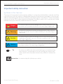
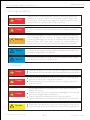
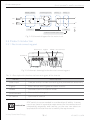
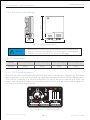
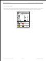
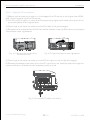
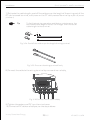
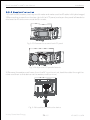
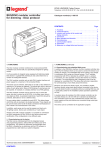
PV Grid-Tied Inverter
1600TL 2200TL 2800TL 3300TL
User Manual
Installer
Operator
Maintainer
EN
Introduction
ShiniCube1600TL-3300TL User Manual
Instruction Manual
About Victory Power
Thank you for use the photovoltaic grid-tied inverter from the research, development and
manufacture of Victory Power.
Victory Power, a high-tech enterprise in the new energy industry, is mainly engaged in the
supply of perfect power source inverting products and technical services for solar
photovoltaic power generation, wind power generation and renewable energy power
generation system, and the products and services are mainly used in the renewable energy
grid-tied power generation system, off-grid village power supply system and private power
supply system.
For readers
This manual is applicable for technicians of inverter installation, operation and maintenance. The reader shall be familiar with electrical knowledge.
About this manual
Please carefully read through this manual before using the product. This manual shall be
well kept in a place easy for using. Persons to operate the product as per this manual must
be a qualified electrical engineer certified by the local electrical authority.
Copyright
The copyright of this manual belongs to Wuxi Victory Power New Energy Technology Co.,
Ltd. No part or the entire of this manual can be reproduced in public without a written
permission.
Because of the continuous product upgrading, this manual will be updated correspondingly,
and thus there will be some unconformity between the manual description and the product,
and the user can acquire the most updated version from www.victorypower.com or Victory
Power will not be responsible for informing the user of manual updating.
Applicable models
This manual provides the instruction for the installation, operation and maintenance of
photovoltaic grid-tied inverters ShiniCube1600TL-ShiniCube3300TL.The following
models of inverter are related:
ShiniCube1600TL
ShiniCube2800TL
ShiniCube2200TL
ShiniCube3300TL
Victory Power New Energy
VP-UMSC1.0.0EN
Introduction
ShiniCube1600TL-3300TL User Manual
Revision
Revised version No.
Date
Description
VP-UMSC1.0.0EN
2011.09.19
Rev. 1
Victory Power New Energy
VP-UMSC1.0.0EN
ShiniCube1600TL-3300TL User Manual
Important safety instruction
Important safety instruction
Symbols in this manual
To ensure the personal and property safety in using the photovoltaic inverter and the
high efficiency of the product, related safe operation notices are provided in the manual,
and corresponding symbols are used for emphasizing the importance. These important
notices must be fully understood and followed. Symbols used in this manual are listed
below to help you carefully read and use this manual.
Danger
It means a highly potential danger which may cause a serious
personal injury or death directly if this warning is neglected.
Warning
It means a moderately potential danger which may cause a
serious personal injury or death directly if this warning is
neglected.
Caution
It means a lightly potential danger which may cause a light or
moderate personal injury or serious property loss if this
warning is neglected.
Notice
It means a potential risk which may cause device malfunction
or property loss if this warning is neglected.
Tip
It means an additional notice emphasizing or complementing
the content, or providing a tip for optimizing the product operation, and further help you solve some problem or save some
time.
Instruction It means a helpful reference or notice.
Victory Power New Energy
VP-UMSC1.0.0EN
Important safety instruction
ShiniCube1600TL-3300TL User Manual
Symbols on the inverter
The inverter is attached with some labels related to operation safety. Please don't install
the device before carefully read through and fully understand these labels.
It means there is still residual voltage in the inverter! The capacitor is still
electrified after the AC/DC side of the inverter is cut off, so the inverter cannot be maintained within 10min till the capacitor is completely discharged.
Danger of high voltage and electric shock!
Danger of high temperature and burn injury!
Earth line!
The wasted product must be sent to the authorized collecting center.
Please carefully read through and fully understand the instruction manual
before using the product.
Certified by Australia AS4777.
Acceptable in the test of insulation and voltage resistance.
Acceptable in the functional test.
Acceptable in the quality inspection.
Victory Power New Energy
VP-UMSC1.0.0EN
ShiniCube1600TL-3300TL User Manual
Contents
Contents
1 Safety instruction ..................................................... ...... ... 1
1 . 1 Before installation ................................................................ 1
1 . 2 During installation ................................................................. 2
1 . 3 Operation ........................................................................... 2
1 . 4 Repair . .............................................................................. 3
1 . 5 EMC ................................................................................. 3
2 Product description ............................................................ 4
2 . 1 Product applicability .............................................................. 4
2 . 2 Circuit structure ................................................................... 4
2 . 3 Product introduction ............................................................. 5
2 . 3 . 1 Electrical connecting part ................................................ 5
2 . 3 . 2 Dimensions and weight .................................................. 6
2 . 3 . 3 LCD Displaying panel ...................................................... 6
2 . 3 . 4 Product label ............................................................... 7
3 Installation ...................................................................... 8
3 . 1 Safety instruction ................................................................ 8
3 . 2 Installation procedures ........................................................... 8
3 . 3 Preparation before installation .................................................. 9
3 . 3 . 1 Unpacking and check ..................................................... 9
3 . 3 . 2 Preparation for tools ..................................................... 10
3 . 4 Selection for a installation position ............................................. 10
3 . 5 Inverter installation .............................................................. 12
3 . 5 . 1 Installation on a wall ...................................................... 12
3 . 5 . 2 Installation on a support ................................................. 13
3 . 5 . 3 Optional anti-theft lock ................................................... 14
Victory Power New Energy
VP-UMSC1.0.0EN
Contents
ShiniCube1600TL-3300TL User Manual
3 . 6 Electrical connection ............................................................. 15
3 . 6 . 1 Electric and electrical system structure ................................. 16
3 . 6 . 2 Structure of the communication system ................................ 16
3 . 6 . 3 Wiring terminals and cable specification ................................ 19
3 . 6 . 4 Steps for electrical connection ........................................... 21
3 . 6 . 5 Earthing requirement ..................................................... 28
4 Trial operation .................................................................. 29
4 . 1 Check before operation ........................................................... 29
4 . 1 . 1 Check for reliability of mechanical installation ......................... 29
4 . 1 . 2 Check for connecting cables .............................................. 29
4 . 1 . 3 Electrical check ............................................................. 29
4 . 2 Electrify the inverter .............................................................. 29
5 Human-machine interaction ................................................... 30
5 . 1 LCD interface ...................................................................... 30
5 . 2 Internal data storage ............................................................. 31
5 . 3 Introduction to the function of monitor software ............................. 32
5 . 3 . 1 Main interface ............................................................. 32
5 . 3 . 2 Device management ...................................................... 32
5 . 3 . 3 Data review ................................................................ 32
5 . 3 . 4 Parameter setting ......................................................... 33
5 . 4 Inverter working mode ............................................................ 33
5 . 4 . 1 Standing-by state ......................................................... 34
5 . 4 . 2 Power generating state ................................................... 34
5 . 4 . 3 Protection state ........................................................... 35
5 . 4 . 4 Fault state .................................................................. 35
Victory Power New Energy
VP-UMSC1.0.0EN
ShiniCube1600TL-3300TL User Manual
Contents
5 . 4 . 5 Fault state ................................................................. 36
5 . 4 . 6 Sleeping state .............................................................. 36
5 . 5 LCD panel power saving mode ................................................... 37
6 Troubleshooting and maintenance ........................................... 38
6 . 1 Troubleshooting ................................................................... 38
6 . 2 Daily maintenance ................................................................ 41
7 Uninstallation ................................................................... 42
7 . 1 Uninstalling steps ................................................................ 42
7 . 2 Packing ............................................................................. 42
7 . 3 Storing .............................................................................. 42
7 . 4 Solution at the termination of service period .................................... 42
8 Technical parameters .......................................................... 43
9 Quality assurance .............................................................. 45
9 . 1 Quality assurance ................................................................. 45
9 . 2 Rights .............................................................................. 45
9 . 3 Exception clause .................................................................. 45
9 . 4 Quality assurance card ........................................................... 46
10 Contact Victory Power ........................................................ 47
10 . 1 About Victory Power ........................................................... 47
10 . 2 Contact Victory Power ........................................................ 47
Victory Power New Energy
VP-UMSC1.0.0EN
safety instruction
ShiniCube1600TL-3300TL User Manual
1 Safety instruction
Tip
Please contact Victory Power if you encounter some puzzle
in reading the following information.
ShiniCube inverters are designed, manufactured and tested as per international safety
standards. However as an electrical and electric product, it must be installed, operated
and maintained strictly according to related safety notices.
Please contact the nearest authorized maintenance center or Victory Power if you need
to maintain or repair the product. Please never repair the product by yourself, or there
may be some personal injury or property loss.
Please don't start to install or debug the device before fully understand all the instruction in the manual and get familiar with all safety symbols in each paragraph.
Victory Power will take no responsibility for any personal injury or property loss caused
by any misoperation.
Warning
Misuse or misoperation may harm:
The personal safety of the operator or a third person;
The property safety of the inverter or any other property.
1 . 1 Before installation
Warning
The inverter cannot be connected to the grid unless approved
by the electrical authority, and it must be installed according
to the local standard and related standard for an electrical
enterprise.
Notice
Please check if the inverter is damaged during transportation
when your receive the product. If you found any defect, please
contact Victory Power and the transportation agency immediately.
Notice
The inverter has electromagnetic radiation, so it is not
suitable for installing in the bedroom or living room, etc.
Please choose a suitable place for installation.
Victory Power New Energy
1 /47
VP-UMSC1.0.0EN
safety instruction
ShiniCube1600TL-3300TL User Manual
1.2 During installation
Danger
Please cover the photovoltaic battery board by lightproof
material or cut off the DC circuit breaker before electrical
connection. A dangerous voltage will be generated by the
photovoltaic array exposed in the sunshine.
Danger
Cables in the photovoltaic power generation system must be
firmly connected, well installed and with suitable specification.
Warning
The output voltage from the array cannot exceed the maximum
input voltage of the inverter. A higher input voltage may
irreversibly damage the inverter or cause some other loss, and
Victory Power will have right to take no responsibility for
quality assurance or any joint and several liability in this case.
Notice
The inverter must be installed by a qualified electrical engineer
certified by the local authority, and the installation manual must
be read through before installation.
Notice
It must be installed according to the local standard and related
standard for an electrical enterprise.
1.3 Operation
Danger
The high voltage circuit in the inverter is dangerous for life safety!
This product must be installed in the place away from any child access.
Danger
There may be an electric shock or fire risk if touching any
contact or terminal in the grid or device;
Please pay attention to all instruction or safety notices for
grid connection.
A damaged device or a system fault may cause an electric
shock or fire risk.
Danger
Caution
Victory Power New Energy
Please visually check if the device is damaged or containing
any other danger before operation;
Check if all external devices and circuits are safely
connected. Make sure the device is safety before operation.
Please take care against burning injury if touching a running inverter;
Only the display screen of the inverter can be touched during operation.
2 /47
VP-UMSC1.0.0EN
safety instruction
ShiniCube1600TL-3300TL User Manual
1.4 Repair
Danger
Cut off the electrical connection between the inverter and the grid
and then cut off the DC electrical connection before repairing.
No repair work can be performed within 10min until the
internal elements are fully discharged
Notice
The inverter cannot be restarted unless any fault influencing
the inverter safety performance is immediately removed.
Please contact the local authorized maintenance man or
Victory Power if you need to repair the inverter.
Notice
Please never dismantle any internal element of the inverter, or
we will take no responsibility for quality assurance or any joint
or several liability for the loss.
1 . 5 EMC
EMC (Electro Magnetic Compatibility) means the resistance of a device or system against
generating any electro magnetic interference to the environment without influencing the
normal operation in the electro magnetic environment.
Immunity to the own noise: immunity to the internal electrical noise;
Immunity to the external noise: immunity to the external electro magnetic noise;
Noise radiation level: influence of electro magnetic radiation to the environment.
ShiniCube is researched, developed and manufactured as per the related international
standard, and the electro magnetic radiation level is very low, but as an industrial product,
it is still important to control the electro magnetic radiation.
Notice
Victory Power New Energy
The electro magnetic radiation of the inverter is harmful for
health;
Please never stay within 20cm from a running inverter for
long.
3 /47
VP-UMSC1.0.0EN
Product description
ShiniCube1600TL-3300TL User Manual
2 Product description
2.1 Product applicability
By the ShiniCube grid-tied inverter, the DC voltage generated in the photovoltaic array can
be transformed into AC voltage supplied to the grid. The photovoltaic power generating
system consists of photovoltaic arrayes, inverters, meters and a power grid.
PV Array
Inverter
Metering
Grid
Fig. 2-1: Photovoltaic grid-tied power generating system
The research, development and manufacture of ShiniCube inverter are integrated with the
most updated techniques and public confirmed safety regulations. However, misoperation
may still cause personal injury or property loss.
The inverter must be reliably connected to the public power grid. This inverter is not
designed for any moving application.
This inverter cannot be used for any other or additional purpose. For any loss caused by
using in any undersigned application, the manufacturer and supplier will take no
responsibility. The user will bear the loss from any undersigned application by himself.
Instruction in this manual must be followed for the designed application.
2.2 Circuit structure
Fig. 2-2 shows the internal functional diagram of ShiniCube inverter. After the photovoltaic
input enters the voltage boosting circuit via the filter circuit, the input DC voltage is boosted
and stabilized to the value for the full-bridge inverter circuit, and in this process, the MPP
tracer in the inverter will ensure the DC energy generated in the photovoltaic array can be
used by the inverter circuit at maximum.
The DC voltage is transformed into AC voltage by the full-bridge inverter circuit. CPU1 and
CPU2 control the inverter operation and monitor the operation state, and in any abnormal
working condition the internal relay of the inverter can be cut off to protect the inverter,
external devices and personal safety.
CPU1 and CPU2 control relay 1 and relay 2 respectively, and thus the system reliability is
highly improved.
Victory Power New Energy
4 /47
VP-UMSC1.0.0EN
Product description
ShiniCube1600TL-3300TL User Manual
Boost
MPPT
Inverting circuit
Relay 1
Relay 2
DC+
L
DC-
N
PE
CPU1
CPU2
Communication port LCD
Fig. 2-2: Schematic diagram for the main circuit
2.3 Product introduction
2.3.1 Electrical connecting part
Solar input
Zigbee
RS485 Grid connect
DC Switch
Fig. 2-3: Schematic drawing for the electrical connecting part
Tab. 2-1: Description for the electrical connecting part of the inverter
Description
Name
Solar Input
Two pairs of terminals connecting the photovoltaic assembly
Zigbee
External optional Zigbee wireless module
RS485
Standard communication mode
Grid Connect
Connected to the grid
DC Switch
Optional DC switch
A DC switch is recommended in consideration of safety. In some
countries, there is imperative requirement for the connection of
Instruction photovoltaic assembly and inverter, so the user can select an
applicable ShiniCube inverter to satisfy the requirement.
Victory Power New Energy
5 /47
VP-UMSC1.0.0EN
Product description
ShiniCube1600TL-3300TL User Manual
480mm
2.3.2 Dimensions and weight
370mm
162mm
Fig. 2-4: Inverter dimensions
Waterproof I/O terminals are located at the bottom of the
inverter, so care must be taken in handing and installing the
inverter to protect these terminals from damage.
Notice
Tab. 2-2: Inverter weight
Model
Weight
ShiniCube1600TL ShiniCube2200TL ShiniCube2800TL ShiniCube3300TL
20Kg
20Kg
20Kg
20Kg
2.3.3 LCD Displaying panel
The inverter works automatically without any user's operating or interfering. The basic
working state including the generating capacity is displayed on the LCD displaying panel.
The inverter displayer is a sound controlled LCD, and it will be turned off and enter the
power saving mode if there is no operation within 2min and will be turned on again by
clicking the inverter shell slightly.
Fig. 2-5: Inverter LCD displaying panel
Victory Power New Energy
6 /47
VP-UMSC1.0.0EN
Product description
ShiniCube1600TL-3300TL User Manual
2.3.4 Product label
The product label, attached to the right side of the inverter, contains the basic information
of the inverter. Please pay attention to the inverter model and technical parameters.
Fig. 2-6: ShiniCube inverter label
Victory Power New Energy
7 /47
VP-UMSC1.0.0EN
Installation
ShiniCube1600TL-3300TL User Manual
3 Installation
3.1 Safety instruction
Danger
The DC voltage at the photovoltaic array side and the AC
voltage at the grid side are both higher than the safe voltage.
It is forbidden to touch any electrified terminal directly. Make
sure the DC side is not electrified before installation and
maintenance.
The inverter must be installed, operated or maintained as per the following standard and
instruction, and it cannot be connected to the grid for power generation unless approved
by the local power supply authority, and all operation must be performed by a qualified
electrical engineer.
All electrical installation must be performed according to the local standard for
electrical installation;
No internal part except the wiring terminals can be touched during installation;
A running inverter has a high voltage, so no internal operation can be made within 10
min at least after the AC and DC power supply of the inverter is cut off and it is made
sure by measuring the DC voltage by a multimeter that the capacity is fully discharged;
Take care of the hot surface of the inverter. E.g.; the heat radiator of the power semiconductor will be kept in a high temperature after the inverter is shut down;
The inverter is delivered without any user's self-maintenance assembly, so please contact
the local authorized installation and maintenance man if you need to maintain your inverter.
3.2 Installation procedures
Start
Prepare
End
Inverter install
Trial run
Electrical install
Check
Fig. 3-1: Installation procedures for the inverter
See the following instruction for details.
Victory Power New Energy
8 /47
VP-UMSC1.0.0EN
Installation
ShiniCube1600TL-3300TL User Manual
3.3 Preparation before installation
3.3.1 Unpacking and check
The product is carefully tested and checked before transportation, but it is still possible
to be damaged during transportation, so please check the device again before installation.
If any damage is found, please contact the transportation agency or directly contact WuXi
Victory Power New Energy Technology Co., Ltd. Please provide us photos of damage, and
we will feed back the fastest and best service.
Please never dispose the original package of your own accord. Check if the delivery is
completed according to the package list. The delivery contains the following items:
Inverter
Installation back board
Allen wrench
Package List
Part
Warranty Card
Customer Information
PV Grid-Tied Inverter
1600TL 2200TL 2800TL 3300TL
Name:
Address:
Zip Code:
E-mail:
Tel:
Fax:
Installation Information
Inverter
Part
Installation back board
PV module type (parameters):
Allen wrench
Number of Strings:
Modules Per String :
System Commissioning Date:
Warranty Card
Installation Company:
Package list
Customer Information
PV Grid-Tied Inverter
Name:
Address:
1600TL 2200TL 2800TL 3300TL
Zip Code:
E-mail:
Tel:
Fax:
Installation Information
Inverter
Part
Installation back board
Allen wrench
1600TL
Customer Information
2200TL
2800TL
Name:
3300TL
Address:
Zip Code:
Number of Strings:
Modules Per String:
System Commissioning Date:
Installation site:
Fax:
Installation Company:
Installation Information
PV module t ype ( parameters):
Number of Strings:
Modules P er String :
System C ommissioning Date:
Installation site:
Installation Company:
Installer Name :
Inverter detailed information
Fault T ime:
Model of Products :
Number of used P roducts:
Installer Name:
Inverter detailed information
Number of Fault Products:
Date of Bill of Lading:
Lading:
1
2
3
4
De sc ri pt ion
Inve rt er
Installation ba ck bo ar d
Qt y
1 shee t
1 shee t
Expa nsion tube s
6 pc s
Tapp ing sc re ws
6 pc s
Tube type pr e- insulated te rm inals
Series No. of Fault Products
Products::
Re ma rk
Fault Messages:
1 se t
1 pc s
1 pc s
1 bo ok
Qu ality as sura nce ca rd
Acce pt ance ce rt ificate
7
8
9
Operator
Pa ckag e li st
User ma nual
5
6
Installer
8 pc s
Inverter detailed information
Brief Fault Description and P hotos(Can be attached):
Chec k the de live ry ac cord ing to the pa ckag e li st.
Pl ea se re ad throug h ca re fully.
Pl ea se we ll ke ep for fi lling an d re turning us if ther e
be come any fa ult in the in ve rt er .
For th e ba ck bo ar d in stallation
For th e ba ck bo ar d in stallation
For co nnec ting comm unication ca bl es
10
OT cold pr es se d te rm inals
8 pc s
For co nnec ting el ec tr ical ca bl es
11
Allen wr ench
1 pc s
For di sm antling th e bo ttom cove r fr om the in ve rt er
Customer Signature:
Date:
Maintainer
For the information on our warranty terms and conditions, please see
our website: http://www.victorypower.com.
WuXi Victory Power New Energy Technology Co., Ltd.
EN
Victor y Power Ne w En ergy
Package list
Warranty card
Certification
Fault Time:
Model of Products :
Number of used Products:
Number of Fault Products:
Date of Bill of Lading
Lading::
Installation back board
3
Package list
1 pcs
User manual
1 book
5
Operator
Series No. of Fault Products:
Products:
Remark
Fault Messages:
Quality assurance card
1 sheet
Acceptance certificate
1 sheet
Please well keep for filling and returning us if there
become any fault in the inverter.
6 pcs
For the back board installation
8
Tapping screws
6 pcs
For the back board installation
Tube type pre-insulated terminals
8 pcs
OT cold pressed terminals
8 pcs
For connecting electrical cables
Allen wrench
1 pcs
For dismantling the bottom cover from the inverter
10
11
Expansion tubes
Brief Fault Description and Photos(Can be attached):
Check the delivery according to the package list.
Please read through carefully.
9
7
Installer
Qty
1 set
1 pcs
2
4
6
User Manual
Description
Inverter
For connecting communication cables
Customer Signature:
Date:
Maintainer
For the information on our warranty terms and conditions, please see
our website: http://www.victorypower.com.
WuXi Victory Power New Energy Technology Co., Ltd.
EN
Victory Power New Energy
Package list
User manual
Installer Name:
E-mail:
Tel:
No .
User Manual
1
Installation site:
PV module type (parameters):
Warranty Card
Package list
PV Grid-Tied Inverter
User manual
No.
Warranty card
Fault Time:
Model of Products :
Number of used Products:
Number of Fault Products:
Date of Bill of Lading:
Certification
Series No. of Fault Products:
Fault Messages:
Description
No.
1
2
3
Operator
Maintainer
Brief Fault Description and Photos(Can be attached):
Installation back board
1 pcs
1 pcs
Package list
Check the delivery according to the package list.
5
Warranty card
1 book Please read through carefully.
Please well keep for filling and returning us if
1 sheet there become any fault in the inverter.
Certification
1 sheet
7
Installer
Remark
1 set
6
4
User Manual
Qty
Inverter
User manual
6 pcs
Expansion tubes
For the back board installation
8
Tapping screws
6 pcs
For the back board installation
9
Tube type pre-insulated terminals
8 pcs
For connecting communication cables
10
OT cold pressed terminals
8 pcs
For connecting electrical cables
11
Allen wrench
1 pcs
For dismantling the bottom cover from the
inverter
Customer Signature:
User manual
Date:
For the information on our warranty terms and conditions, please see
our website: http://www.victorypower.com.
EN
Victory Power New Energy
Warranty card
Package list
Certification
Fig. 3-2: Items in the package
Tab. 3-1: Package list
No.
Description
Qty
Remark
1
Inverter
1 set
2
Installation back board
1 pcs
3
Package list
1 pcs
4
User manual
1 book
5
Warranty card
Please well keep for filling and returning us if
1 sheet there become any fault in the inverter.
6
Certification
1 sheet
7
Expansion tubes
6 pcs
For the back board installation
Check the delivery according to the package list.
Please read through carefully.
8
Tapping screws
6 pcs
For the back board installation
9
Tube type pre-insulated terminals
8 pcs
For connecting communication cables
10
OT cold pressed terminals
8 pcs
For connecting electrical cables
11
Allen wrench
1 pcs
For dismantling the bottom cover from the
inverter
Victory Power New Energy
9 /47
VP-UMSC1.0.0EN
Installation
ShiniCube1600TL-3300TL User Manual
3.3.2 Preparation for tools
The following tools will be used for installing the inverter:
ф6 percussion drill
Press pinchers
Screw driver and wrench
Multimeter
Hammer
Fig. 3-3: Tools for installation
3.4 Selection for a installation position
Danger
Notice
Notice
Victory Power New Energy
Some parts (e.g.: heat radiator) of the inverter runs with a high
temperature, so it is not suitable for installing near inflammables or explosives.
When selecting an installation position, please avoid the
influence of noise and electro magnetic radiation to the
environment;
The inverter cannot be installed near any place of high
external electro magnetic radiation (e.g.: a TV tower,
communication signal tower or HV cables).
The inverter performance will be degraded if the environmental
temperature is 45℃ above. Make sure the inverter is installed
in a well ventilated place so that the power generation can be
maximized.
10 /47
VP-UMSC1.0.0EN
Installation
ShiniCube1600TL-3300TL User Manual
Detailed requirement for the installation position:
The inverter with a protection level of IP65 can be installed in the open air;
The inverter cannot be installed under direction sunshine, or the internal temperature
of the inverter will be excessively high and thus the inverter performance will be
degraded for protecting the internal elements; or even the temperature protection
will be activated by the excessively high temperature;
The inverter shall be installed in a clean environment that the environmental temperature is -25 OC ― + 60 OC;
The environmental relative humidity is not higher than 95% and without any
condensation;
The inverter LCD shall be leveled with eyes and with enough space in the front for
inspection;
For avoiding burning injury or electric shock, the inverter shall be installed beyond the
touch distance of a child. The temperature of some parts (e.g.: the heat radiator) is
quite high when the inverter is running;
Make sure the installation position will not shake;
The inverter shall be installed in a well ventilated place to ensure the normal heat
radiation;
The installation place shall be firm enough to support the inverter weight for long;
The inverter shall be installed on a vertical wall, or within 15° at most if backwards to
the wall.
Connecting terminals are located at the bottom.
Fig. 3-4: Selecting a position for installation
Victory Power New Energy
11 /47
VP-UMSC1.0.0EN
Installation
ShiniCube1600TL-3300TL User Manual
40cm
40cm
50cm
20mm
40mm
40mm
50mm
40cm
Min. size (cm)
Front
Lateral
Top
Bottom
50cm
Position
40cm
Tab. 3-2: Effective spacing dimensions
Fig. 3-5: Schematic drawing for the
minimum spacing dimensions for
inverter installation
3.5 Inverter installation
Take out the back board from the package, and then install the back board on the firm wall
by expansion screws or on a metal support by bolts.
3.5.1 Installation on a wall
If the inverter is to be installed on a firm wall, please operate as per the following steps:
1) Take out the back board and mark the installation holes;
2) Drill holes in the marked position as per the size of expansion screws;
3) Insert the expansion tubes into the hole, knock the tubes into the hole and make
them level with the wall surface;
4) Fix the back board to the wall by the tapping screws tightly;
240mm
35mm
120mm
Expansion tubes
Back board
Tapping screws
Fig. 3-6: Schematic drawing for back board installation (on a wall)
Victory Power New Energy
12 /47
VP-UMSC1.0.0EN
Installation
ShiniCube1600TL-3300TL User Manual
5) Carefully lift up the inverter and hang it on the back board slowly according to the notch
and slot, and then visually check if the inverter is correctly installed;
1
2
Fig. 3-7: Schematic drawing for inverter installation (on a wall)
6) After installation, you can choose if it is necessary to attach the inverter with an anti-theft
lock.
Tip
The anti-theft lock is not in the scope of delivery, and you need
to equip one by yourself. See 3.5.3 for the specification of the
anti-theft lock.
3.5.2 Installation on a support
If the inverter is to be installed on a metal support, the support must be thick enough to
bear the inverter weight:
1) Take out the back board and place the board on the metal support horizontally;
2) Mark the positions for drilling holes according to the back board specification;
Tip
If the hole position on the back board is not matched with the
support, it is recommended to replace a support other than to
drill new holes on the back board. Drilling new holes on the
back board will unbalance the stress on the board, and Victory
Power will take no responsibility for such unexpected situation
if any.
3) In this installation mode, bolts M5*50 and corresponding nuts can be used for fixing the
back board. These fasteners are not covered in the scope of deliver, and shall be equipped
by the user of own cost. Drill holes at the marked position on the installation support as
per the specification of the fasteners;
Tip
Victory Power New Energy
Bolts supplied by the user shall be M5*50 or longer bolts for
thicker support. Bolts shall be selected in consideration of the
support thickness.
13 /47
VP-UMSC1.0.0EN
Installation
ShiniCube1600TL-3300TL User Manual
4) Install the back board on the support by the fasteners;
Gasket
Clips
M5 * 50 Hexagon nut
Back board
M10 Hexagon headed bolt
Support
Fig. 3-8: Schematic drawing for back board installation (on a support)
5)Carefully lift up the inverter and hang it on the back board slowly according to the notch
and slot, and then visually check if the inverter is correctly installed;
1
2
Fig. 3-9: Schematic drawing for inverter installation (on a support)
6)After installation, you can choose if it is necessary to attach the inverter with an
anti-theft lock.
3.5.3 Optional anti-theft lock
An anti-theft lock can be used to lock the inverter on the back board and protect the outdoor installed inverter from theft.
Fig. 3-10: Schematic drawing for an anti-theft lock
Victory Power New Energy
14 /47
VP-UMSC1.0.0EN
Installation
ShiniCube1600TL-3300TL User Manual
The lock size shall satisfy the following requirement:
A
B
Size:
A: 3 mm - 6 mm
B: 30mm - 40mm
C: 30mm - 40mm
C
Fig. 3-10: Size of an anti-theft lock
Notice
The anti-theft lock selected must be suitable for outdoor
installation;
Regularly check if the lock can be normally opened;
The key to the anti-theft lock must be well kept.
3.6 Electrical connection
After the inverter is correctly installed on the wall or support, the next step is the electrical
connection for the inverter. Electrical connection must be performed according to related
safety standards.
Danger
A misoperation electrical connection may cause personal injury
or death or damage the inverter irreversibly. Wiring operation
must be performed by a qualified electrical engineer.
Warning
All electrical installation must be complying with local and
national electrical standards.
Warning
The inverter cannot be connected to the grid unless approved
by the local electrical authority and all electrical connections
are completed by a qualified electrical engineer.
Warning
Please use cables of specification recommended by us, or the
system safety may be degraded.
The electrical connection for an inverter covers electrical cable connection and communication cable connection.
Victory Power New Energy
15 /47
VP-UMSC1.0.0EN
Installation
ShiniCube1600TL-3300TL User Manual
3.6.1 Electric and electrical system structure
The electric and electrical connection for the whole solar energy power generation system
is shown as below:
Inverter
RCD
AC Breaker
PV Array
SPD
DC Breaker
GRID
SPD
Fig. 3-12 Schematic drawing for the electrical cable connection of the inverter
The PV array is connected to the inverter via a DC breaker, the inverter is connected to the
grid via an AC breaker and a residual current device (RCD), and surge protection device
(SPD) are configured on the AC and DC sides respectively.
No load can be directly connected to the output side of the inverter.
3.6.2 Structure of the communication system
ShiniCube supports two flexible communication modes: RS485 and optional wireless
Zigbee. The topological structure of the communication connection is introduced below.
Tip
See 3.6.3 for the detailed wiring terminals and 3.6.4 for the
detailed wiring steps.
Communication between a single device and a PC
1) Single device communication mode 1 (RS485)
See the figure below for the connecting method, a pair of A/B terminals on the inverter is
connected to the A/B terminals on the RS485/RS232 or RS485/USB switch, and the other
end of the switch is connected to the computer.
R S 485
RS232/USB
Fig. 3-13: Schematic drawing for the single device communication mode 1
Victory Power New Energy
16 /47
VP-UMSC1.0.0EN
Installation
ShiniCube1600TL-3300TL User Manual
2) Single device communication mode 2 (wireless Zigbee module)
The connecting method is shown below, and a pair of wireless Zigbee modules is
installed on the inverter and computer.
Fig. 3-14: Schematic drawing for the single device communication mode 2
Communication between multiple devices and a PC
1) Multi-device communication mode 1 (RS485)
See the figure below for the connecting method, A/B terminals on the inverter are paralleled
and then connected to the A/B terminals on the RS485/RS232 or RS485/USB switch, and
the other end of the switch is connected to the computer. 32 inverters can be connected by
this mode.
RS485
RS485
RS485
RS232/USB
Fig. 3-15: Schematic drawing for the multi-device communication mode 1
Tip
The "Multi-device communication mode 1" with RS485 is
applicable for centralized installation where wiring is
convenient between the computer and devices.
2) Multi-device communication mode 2 (RS485 and Zigbee module)
See the figure below for the connecting method, A/B terminals of inverters are paralleled,
and a pair of Zigbee module is installed on any one of the inverters and the PC. 32 inverters
can be connected by this mode.
Victory Power New Energy
17 /47
VP-UMSC1.0.0EN
Installation
ShiniCube1600TL-3300TL User Manual
RS485
RS485
Fig. 3-16: Schematic drawing for the multi-device communication mode 2
Tip
The "Multi-device communication mode 2" with RS485 and
Zigbee is applicable for centralized installation where wiring is
not convenient between the computer and devices. This
communication mode is recommended.
3) Multi-device communication mode 3 (Zigbee module)
The connecting method is shown below, each inverter and the PC is installed with a Zigbee
module. 100 inverters can be connected by this mode.
Fig. 3-17: Schematic drawing for the multi-device communication mode 3
Tip
The "Multi-device communication mode 3" with Zigbee
modules are applicable for decentralized installation in which
wiring is not convenient.
Tip
If RS485 communication mode is selected, it is recommended
to use two-core dual-twisted shield cable. The recommended
specification is RVVP2*1.0. The maximum transmission
distance of RS485 communication mode is 1200m.
Tip
RS485/RS232 switch module, RS232/USB switch module and
Zigbee wireless module are serial products orderable from
Victory Power RS485/RS232 switch module and RS232/USB
switch module can be purchased by the user of own.
Notice
Victory Power New Energy
Zigbee wireless communication is functioning within 1200m in
an opening distance, but interference and barrier shall be put
into consideration because the actual transmission distance is
influenced by the installation field and external interference.
18 /47
VP-UMSC1.0.0EN
Installation
ShiniCube1600TL-3300TL User Manual
3.6.3 Wiring terminals and cable specification
1) DC wiring terminals
The DC side has 4 terminals totally, two pairs of positives and negatives. See the figure below:
Fig. 3-18: DC wiring terminals
2) AC wiring terminals
The AC side has three terminals: L, N and GND, in which, GND is located on the shell, shown
in the figure below:
Fig. 3-19: AC wiring terminals
3)Communication terminals
The inverter has six communication terminals: two pairs of A/B, +5V and GND.
See the figure below:
Fig. 3-120: Communication terminals
Victory Power New Energy
19 /47
VP-UMSC1.0.0EN
Installation
ShiniCube1600TL-3300TL User Manual
Tab. 3-3: Meaning of communication terminals
Terminal SN
Corresponding cable
Terminal name
RS485 communication cable B or Zigbee module
communication cable B (blue)
L1
B1
L2
A1
L3
B2
L4
A2
L5
+5V
RS485 communication cable A or Zigbee module
communication cable A (green)
Zigbee module power supply cable +5V (red)
L6
GND
Zigbee module power supply cable GND (black)
RS485 communication cable A or Zigbee module
communication cable A (green)
RS485 communication cable B or Zigbee module
communication cable B (blue)
Tip
The Zigbee wireless communication module at the inverter side
has a cable with 4 wires inside (blue, green, red and black)
corresponding to the wiring terminals B, A, +5V and GND, in
which, the inverter wiring terminals have two pairs of A/B, and
each pair can be connected.
Tip
The two pairs of A/B wiring terminals at the inverter
communication side are equivalent. A/B of Zigbee module and
A/B of RS485 can be connected with no difference.
Single-device communication: either pair of A/B terminals
can be connected if Zigbee module or RS485 module is
connected.
Multi-device communication: either pair of the A/B terminals
can be connected to the Zigbee module and the other pair to
RS485 if Zigbee module and RS485 are both connected.
Multi-device communication: two routes of RS485 can be
connected, and either pair of A/B terminals can be used
as the input and the other pair as the output.
4) Cables of the following specification will be equipped by the user of own cost.
Tab. 3-4: Recommended cable specification
Min. sectional area
(mm 2)
Max. sectional area
(mm 2)
Recommended
2
sectional area (mm )
DC cable (+)
2
4
4
DC cable (-)
AC cable (L)
2
4
4
6
4
4
AC cable (N)
4
6
4
AC cable (GND)
4
6
4
0.5
1.5
1
Name
Communication
cable (RS485)
Victory Power New Energy
20 /47
VP-UMSC1.0.0EN
Installation
ShiniCube1600TL-3300TL User Manual
3.6.4 Steps for electrical connection
Danger
Please cover the photovoltaic battery board by lightproof
material or cut off the DC circuit breaker before electrical
connection. A dangerous voltage will be generated by the
photovoltaic matrix exposed in the sunshine.
Danger
If the inverter has been electrified and tested before connection, wiring cannot be performed unless the AC and DC power
supplies are cut off for 10min and a multimeter shows that
the DC side is totally discharged.
Caution
When designing the PV array, make sure the maximum open
circuit voltage is not higher than 550V at each series of PV
group. Otherwise the inverter will be damaged irreversibly.
Tip
Different colors of cables shall be used for differentiating
in assembling. E.g.: the positive pole is connected by a red
cable and the negative by a blue cable.
Tip
To balance each PV series, cables shall be with the same
sectional area.
Tip
DC cable between the inverter and the assembly shall be
the special PV cable. The voltage drop from the terminal
box to the inverter is about 1-2%. It is recommended the
inverter is installed on the assembly support for generation
to reduce the cable cost and DC loss.
Tip
High performance and high quality PV assemblies shall be
used. The open circuit voltage in the serial array must be lower
than the maximum DC input voltage in the PV grid-tied inverter,
and the working voltage of the serial array must comply with
the MPPT voltage in the PV grid-tied inverter.
Notice
Victory Power New Energy
Protect the LCD panel during wiring;
Protect the LCD panel and other elements from scratch or
damage by cables or tools.
21 /47
VP-UMSC1.0.0EN
Installation
ShiniCube1600TL-3300TL User Manual
3.6.4.1 Steps for DC connection
1) Make sure the maximum open circuit voltage of the PV series is not higher than 550V,
and check the polarity of the PV series;
2) Cut off the DC breaker, or cover the PV assembly by lightproof material to ensure the
personal safety of wiring operator;
3) Check by a multimeter to make sure the DC cable is fully discharged;
4) Remove the 4 screws at the left of the inverter bottom cover by Allen wrench, and open
the bottom cover rightwards;
Fig. 3-21: Remove the screws from
the bottom cover
Fig. 3-22: Open the bottom cover rightwards
5) Check by a multimeter to make sure the DC wiring terminal is fully discharged;
6) Remove the waterproof cover from the DC input terminal, lead the cable through the
cover and then to the device via the waterproof terminal;
Fig. 3-23: Lead the DC cable to the device
Victory Power New Energy
22 /47
VP-UMSC1.0.0EN
Installation
ShiniCube1600TL-3300TL User Manual
7) Estimate the cable length, peel off the cable as per the length of the wiring part of the
OT cold pressed terminal, and press on the OT cold pressed terminal by a pair of press
pinchers;
Tip
To facilitate wiring operation and device maintenance, the
estimated cable length shall be 10cm longer than the actual
cable length to the terminal.
L
L
Fig. 3-24: Peel off the cable as per the length of wiring terminal
Fig. 3-25: Press on the wiring terminal firmly
8) Connect the cable to the wiring terminal by a screw driver reliably;
Fig. 3-26: Connect the DC cable reliably
9) Tighten the waterproof DC input terminal cover;
10) Connect all DC cables reliably as per the steps above.
Victory Power New Energy
23 /47
VP-UMSC1.0.0EN
Installation
ShiniCube1600TL-3300TL User Manual
3.6.4.2 Steps for AC connection
1) Cut off the AC breaker, check by a multimeter and make sure the AC cable is fully discharged;
2)Remove the screws from the top right of the LCD panel, and open the panel leftwards to
disclose the AC and communication terminals;
Fig. 3-27: Remove the screws from LCD panel
Fig. 3-28: Open the LCD panel leftwards
3) Remove the waterproof cover from the AC input terminal, lead the cable through the
cover and then to the device via the waterproof terminal;
Fig. 3-29: Lead the AC cable to the device
Victory Power New Energy
24 /47
VP-UMSC1.0.0EN
Installation
ShiniCube1600TL-3300TL User Manual
4) Estimate the cable length, peel off the cable as per the length of the wiring part of the
OT cold pressed terminal, and press on the OT cold pressed terminal by a pair of press
pinchers;
Tip
To facilitate wiring operation and device maintenance, the
estimated cable length shall be 10cm longer than the actual
cable length to the terminal.
L
L
Fig. 3-30: Press on the wiring terminal firmly
5) Connect the cables respectively to terminals L, N and GND by a screw driver, in which,
GND is located on the shell of the inverter;
Fig. 3-31: Connect the AC cable reliably
6) Tighten the waterproof AC terminal cover.
7)This step can be jumped over if the communication cable is to be connected. Check if
the AC and DC cables are reliably connected, record the cable colors and corresponding
functions, close the LCD panel and the bottom cover of the inverter if it is unnecessary
to connect the communication cable. Jump over the following part and turn to "3.6.5
Requirement for earthing".
Victory Power New Energy
25 /47
VP-UMSC1.0.0EN
Installation
ShiniCube1600TL-3300TL User Manual
3.6.4.3 Connect RS485 as per the following steps.
1) Remove the waterproof cover from the RS485 terminal, lead the cable through the cover
and then to the device via the waterproof terminal;
2) Estimate the cable length to the terminal, peel off the cable as per the length of the
metal section of the tube type pre-insulated terminal, and press on the terminal by a pair
of press pinchers reliably;
L
L
Fig. 3-32: Press on the RS485 wiring terminal
GND +5V A 2 B 2 A 1 B 1
3) Press down the top of the terminal by a flat screw driver, insert the tube type
pre-insulated terminal into the corresponding inverter terminal, and then loosen the
screw driver. Firmly connect the cable to the device terminals A/B respectively, and
record the corresponding cable colors;
Fig. 3-33: RS485 reliable connection
4) Tighten the waterproof RS485 terminal cover.
Victory Power New Energy
26 /47
VP-UMSC1.0.0EN
Installation
ShiniCube1600TL-3300TL User Manual
3.6.4.4 Connect Zigbee wireless module as per the following steps.
1) Zigbee wireless communication module has a cable with four wires inside: blue, green,
red and black corresponding to terminal B, A, +5V and GND correspondingly.
2) Remove the waterproof cover from the Zigbee terminal, lead the cable through the cover
and then to the device via the waterproof terminal;
3) Estimate the cable length to the terminal, peel off the cable as per the length of the
metal section of the tube type pre-insulated terminal, and press on the terminal by a pair
of press pinchers reliably;
L
L
Fig. 3-34: Press on the Zigbee wiring terminal
GND +5V A 2 B 2 A 1 B 1
4) Press down the top of the terminal by a flat screw driver, insert the tube type
pre-insulated terminal into the corresponding inverter terminal, and then loosen the
screw driver. Firmly connect the blue, green, red and black wires correspondingly to
terminals B, A, +5V and GND;
Fig. 3-35: Zigbee module reliable connection
5) Tighten the waterproof Zigbee terminal cover.
6) After all cables are connected, check if the AC and DC cables are reliably connected,
record the cable colors and corresponding functions, close the LCD panel and the bottom
cover of the inverter.
Victory Power New Energy
27 /47
VP-UMSC1.0.0EN
Installation
ShiniCube1600TL-3300TL User Manual
3.6.5 Earthing requirement
Caution
The inverter is a device with no transformer, neither the
positive nor the negative pole of the PV assembly DC side can
be earthed, or the inverter will not work normally, or even be
damaged irreversibly.
In ShiniCube PV power generation system, all device shells, assembly supports and the
GND terminal of the inverter must be safely and reliably earthed.
Victory Power New Energy
28 /47
VP-UMSC1.0.0EN
Trial operation
ShiniCube1600TL-3300TL User Manual
4 Trial operation
4.1 Check before operation
Warning
Necessary safety check must be performed before the inverter
is electrified for trial operation!
4.1.1 Check for reliability of mechanical installation
Check if the inverter is firmly installed and if all bolts are reliably tightened. For an
inverter installed on a metal support, make sure each bolt is tightened and the support
has enough load bearing capacity.
4.1.2 Check for connecting cables
Check if all cables in the system are firmly connected without any missed or wrong
connection, and especially check if all positive and negative poles are correct. If a DC
switch is equipped on the inverter, the DC switch shall be turn to the "OFF" state.
4.1.3 Electrical check
Make sure the DC input voltage of the inverter is lower than 550V (with the temperature
decrease of the PV assembly, the open circuit voltage will be increased, so a residual
voltage at the low temperature must be put into consideration).
Make sure the grid parameters are complying with the inverter parameters.
4.2 Electrify the inverter
The inverter can be started up as per the following steps after all testing and checking
steps are performed.
Close the DC breaker, and turn the DC switch to the "ON" state if a DC switch is equipped
on the inverter.
Close the AC breaker;
See Part 5 of this manual for "Human-machine interaction" after the inverter is started
up. If enough power energy can be generated in the solar array, the inverter will be
started up automatically, and LCD will display the normal state which means the inverter
is successfully started up. If the inverter is not normally started up, pleaser refer to Part
6 "Troubleshooting and maintenance".
Victory Power New Energy
29 /47
VP-UMSC1.0.0EN
Human-machine interaction
ShiniCube1600TL-3300TL User Manual
5 Human-machine interaction
5.1 LCD interface
7
6
5
4
3
8
2
1
9
12
10
13
11
14
16
18
15
17
Fig. 5-1: LCD displaying panel
Tab. 5-1: Introduction to symbols on the LCD panel
SN
Description
Symbol
1
It means the inverter is running normally (sleeping, standing-by
and power generating states)
2
The inverter enters the protection state.
3
The inverter enters the fault state.
4
The PV system is running normally, and the "coin" symbol means
the system is generating power.
5
It dynamically means the LCD is in the power saving state, and the
LCD will turn to the normal displaying mode if knocking the
inverter shell by a finger lightly.
6
The twinkling speed means the voltage intensity at the AC side
7
The "normally on" state means the inverter is running normally.
The "twinkling" state means the inverter is in the fault state.
8
The twinkling speed means the voltage intensity at the DC side
Victory Power New Energy
30 /47
VP-UMSC1.0.0EN
Human-machine interaction
SN
ShiniCube1600TL-3300TL User Manual
Description
Symbol
9
It means the communication state of the inverter.
10
The dynamic state means there is fault in the DC side, the static
state means there is voltage at the DC side.
11
The dynamic state means there is fault in the AC side, the static
state means there is voltage at the AC side.
12
When the system is running normally, powers are displayed by a
column chart, and the minimum unit is 150W or 200W (as per the
actual value displayed).
13
/
/
: current power;
: mean power;
: maximum power;
: minimum power
14
It indicates the current power, unit: KW; when displaying
dynamically, the value below indicates the real-time power.
15
It indicates the electric quantity of the current day, unit: KWh, and
the value below means the electric quantity of the current day.
16
It indicates the total electric quantity, unit: KWh or MWh (as per
the actual value displayed), and the value below means the total
electric quantity.
17
It means the system enters the "protection state", this symbol is
displayed dynamically, and the value below means the protection
code (see Part 6 of this manual for details).
18
It means the system enters the "fault state", this symbol is
displayed dynamically, and the value below means the fault code
(see Part 6 of this manual for details).
5.2 Internal data storage
This device has the calendar and data storage function, and detailed data storage for
200 days can be realized without any external data collector.
1) History data storage
Data will be stored once per minute, the data stored include the total power generated,
I/O power, I/O current, I/O voltage and power factor at the storing time point.
2) Running state record
It can save the running state of the device, including the starting time point and ending
time point of the running state, so that the user can check the running state conveniently.
3) Device fault/ protection event record
It stores the type and time point of any fault or protection event.
Victory Power New Energy
31 /47
VP-UMSC1.0.0EN
Human-machine interaction
ShiniCube1600TL-3300TL User Manual
5.3 Introduction to the function of monitor software
ShiniCube inverter can realize data reviewing and parameter setting, etc by the monitor
software, the following is a brief introduction to the monitor software, and for more details
please read the instruction manual for the monitor software.
Tip
You can download the most updated monitor software and
the corresponding user's manual on our website :
www.victorypower.com.
5.3.1 Main interface
1) Device list zone: names of all registered devices with the communication state (LIVE or
OFF) are displayed by a module tree, and one of the device can be selected as the current
device by clicking.
2) Accumulated data displaying zone: the total electric quantity, current day power
generated, total power generating time and the current running state of each device in
the device list are displayed by a data table.
3) Current device real-time data zone: the real-time data of the current data including
the I/O power, I/O current, I/O voltage, power factor and efficiency of the current device
are displayed by a data table.
4) Current device current day data curve: the data curve of the current device including the
current day power generated, input power and output power are displayed by curves.
5.3.2 Device management
1) Device registration: a new device can be added into the device list by the user;
2) Device modification: the name of a registered device can be modified by the user;
3) Device deletion: a dismantled device can be deleted from the device list by the user;
5.3.3 Data review
1) History data curve
The history data curve for each device of any day during the storage period can be reviewed,
and the data include the generated electric quantity, I/O power, I/O current and I/O voltage
of the day reviewed.
2) History generated electric quantity
The generated electric quantity during a section of storage period for each device in the
device list can be reviewed, including the total quantity, weekly quantity, monthly
quantity and yearly quantity.
3) The system information of each device in the device list can be reviewed, including the
running state information and fault/ protection information of the device.
Victory Power New Energy
32 /47
VP-UMSC1.0.0EN
Human-machine interaction
ShiniCube1600TL-3300TL User Manual
5.3.4 Parameter setting
1) Serial port setting: select the serial port number for device communication;
2) Device selecting: select the device to be set;
3) Time setting: set the time of the current device;
4) Safety standard review: review the safety standard for the current device;
5) Safety standard setting: set the safety standard for the current device, and this function
needs to be verified by a password.
Warning
The safety standard for the inverter cannot be modified of own
accord, the modified standard shall comply with the local grid
standard, and the safety standard setting must be performed
by a qualified electrical engineer who is familiar with ShiniCube
inverter and the local power grid. A wrong safety standard
setting may cause some damage of device or cancellation of
grid connecting license, and in this case Victory Power will
take no consequential responsibility.
5.4 Inverter working mode
After the inverter is started up, the normal working state will be switched as per the
chart below:
DC<100V
No AC
Sleeping
Power off
DC<100V
AC Normal
DC>100V
AC Normal
T Z Self-detect
T Z=6 - 10S
DC<100V
No AC
DC<100V
AC Normal
DC>100V
AC Normal
Device fault/environmental
abnormity
DC>150V
AC Normal
T d Waiting
T d =20-30S
Fault/protection recovery
T h Self-detect
T h=60-100S
DC>150V
AC Normal
Device fault/environmental abnormity
Fault/ Protection
Standing-by
Power generating
Fault/protection recovery
T h Self-detecting
T h=60-100S
Fig. 5-2: Schematic chart for the switch of working mode
Victory Power New Energy
33 /47
VP-UMSC1.0.0EN
Human-machine interaction
ShiniCube1600TL-3300TL User Manual
See the following content for the meaning of each state.
5.4.1 Standing-by state
When the DC voltage output from the solar battery at the DC side is higher than 100V
(min. initiating voltage) but lower than 150V (min working voltage), the inverter will enter
the standing-by state and not supply power to the gird. In this case, the inverter will keep
monitoring the voltage on the solar batter board, and will enter the power generating
state once it reaches the working voltage 150V.
Fig. 5-3: LCD panel at the standing-by state
5.4.2 Power generating state
The inverter will enter the power generating state if the DC voltage output from the solar
battery board at the DC side is higher than 150V.
Fig. 5-4: LCD panel at the power
generating state
Victory Power New Energy
34 /47
VP-UMSC1.0.0EN
Human-machine interaction
ShiniCube1600TL-3300TL User Manual
See the following content for the meaning of each state.
5.4.3 Protection state
If any external fault such as AC side grid fault is detected by the inverter, the inverter will
stop power generating and enter the protection state, in this case the yellow indicator on
the right top of the LCP panel will turn on and display the corresponding protection code.
Troubleshooting can be performed by the user according to this code. The inverter will
keep monitoring if the external fault is removed, and will keep in the protection state
unless the fault is removed. It will be reenter the grid-connect power generating mode if
the fault is removed.
Fig. 5-5: LCD panel at the protection state
5.4.4 Fault state
If any internal fault is detected by the inverter, the inverter will stop power generating
and enter the fault state, in this case the red indicator on the left top of the LCP panel will
turn on and display the corresponding protection code. Troubleshooting can be performed
by the user according to this code. The inverter will keep monitoring if the internal fault
is removed, and will keep in the protection state unless the fault is removed. It will be
reenter the grid-connect power generating mode if the fault is removed.
Fig. 5-6: LCD panel at the fault state
Victory Power New Energy
35 /47
VP-UMSC1.0.0EN
Human-machine interaction
ShiniCube1600TL-3300TL User Manual
When the inverter enters the protection or fault state, and there are two or more
protection or fault codes at the same time, in this case it means the system or inverter
may be involved with two or more faults. The code below the protection or fault symbol
will change alternatively in different protection or fault states.
Fig. 5-7: LCD panel displaying two faults alternatively at the same time
5.4.5 Sleeping state
If the DC voltage output from the solar battery at the DC side is lower than 100V (minimum
initiating voltage) and there is voltage at the grid side, the inverter will enter the sleeping
mode and the LCD panel will display nothing. In this case the related data can be reviewed
if knocking the inverter shell by a finger slightly.
Fig. 5-8: Reviewable LCD panel at the sleeping state
5.4.6 Power-off state
If the DC voltage output from the solar battery at the DC side is lower than 100V (minimum
initiating voltage) and there is no voltage at the grid side, the inverter will enter the
power-off mode and the LCD panel will display nothing.
Victory Power New Energy
36 /47
VP-UMSC1.0.0EN
Human-machine interaction
ShiniCube1600TL-3300TL User Manual
5.5 LCD panel power saving mode
Tip
If the inverter is running but is not operated for a long time,
the LCD panel will automatically enter the power saving
mode after about 2min, and in this case the related data can
be reviewed by the user if knocking the inverter shell by a
finger slightly.
Fig. 5-9: LCD panel power saving mode
Victory Power New Energy
37 /47
VP-UMSC1.0.0EN
Troubleshooting and maintenance
ShiniCube1600TL-3300TL User Manual
6 Troubleshooting and maintenance
6.1 Troubleshooting
This part introduces the common faults and solving steps, provides troubleshooting
method and skills to the user, and helps the user identify and solve some common fault
of the inverter.
Tip
Faults mentioned in this part means the inverter enters the
protection state or fault state.
The protection state is mostly caused by some external reasons, e.g.: the DC voltage is too
high, the inverter output is not matched with the grid, the grid is power off or the system
is not correctly earthed, and thus the inverter acts to ensure the own safety. The inverter
itself has no defect and can be recovered from the protection state if the system is correctly
designed and installed.
Sometimes the inverter enters the protection state by the own defect and can be recovered
by resetting or repairing.
The fault state is caused by the own defect of the inverter, and thus the inverter acts to
protect the system safety. The inverter can be recovered from some faults automatically
or by resetting, and some faults are caused by the own defect of the inverter, and in this
case the inverter cannot be recovered and shall be repaired.
Correctly identifying the fault state of the inverter is helpful for solving the fault, so please
treat as per the following steps:
1) Check if the state displayed on the panel is a protection state or fault state, and record
all error codes;
2) Try the solution listed in Tab. 6-1 and 6-2 and meanwhile check as per the following steps;
If the voltage at the AC/DC side is normal and if the breaker is opened?
If the inverter is installed in a clean, dry and well ventilated place?
If the cable sectional area satisfies the requirement?
If the connecting cable is too long?
If all cables are firmly connected?
If wiring is reasonable?
If the safety standard setting is correct?
3) If you meet any problem that you cannot solve it by yourself, please contact the client
service man of Victory Power For the optimal solution, please provide use the detailed
system installation information, inverter model, serial number and fault information.
Victory Power New Energy
38 /47
VP-UMSC1.0.0EN
Troubleshooting and maintenance
ShiniCube1600TL-3300TL User Manual
Tab. 6-1: Protection code and solution
Displayed
code
Protection description
P001
The leakage
current is too high
P002
The voltage at the
grid side is too high
P003
The voltage at the
grid side is too low
P004
The frequency at the
grid side is too high
P005
The frequency at the
grid side is too low
P006
Islanding protection
P007
The insulating
impedance is too low
P013
The DC current input
is too high
P014
The DC voltage is
too high
Victory Power New Energy
Recommended solution
1.Cut off the DC breaker and check if there is abnormity in the AC side;
2.After the fault is removed, close the DC breaker
and restart the inverter;
3.If the fault occurs repeatedly, pleas ask for
professional service.
1.Check if the inverter is normally connected to
the grid;
2.Check if the grid voltage and frequency are
complying with the output scope of the inverter;
3.If the fault above is removed but the inverter can
still not work normally, please ask for professional
service.
1.Cut off the DC breaker;
2.Check if the resistance between the +/- poles of
the PV assembly and the ground is larger than1MΩ;
3.If the fault above is removed but the inverter can
still not work normally, please ask for professional
service.
1.Cut off the DC breaker;
2.Check if DC input is higher than 550V;
3.If the fault above is removed but the inverter can
still not work normally, please ask for professional
service.
39 /47
VP-UMSC1.0.0EN
Troubleshooting and maintenance
ShiniCube1600TL-3300TL User Manual
Tab. 6-2: Fault code and solution
Displayed
code
Fault description
E001
Relay fault
E002
The voltage at the
grid side is too high
E003
Abnormity of CPU
synchronous communication
E004
E 2 ROM read-write
abnormity
E006
Leakage current
detecting circuit fault
E009
The AC voltage
output is too high
E010
The DC voltage branched
from the AC voltage output
is too high
E011
The BUS voltage
is too high
E012
The BUS voltage is
too low
E013
The IGBT temperature
is too high
E014
BOOST fault
E015
Inverting fault
E017
The BUS capacity is aged
E022
The voltage dependent
resistor at the output side
is broken
E023
The voltage dependent
resistor at the input side
is broken
E024
FLASH read-write
abnormity
Victory Power New Energy
Recommended solution
1.Cut off the DC breaker;
2.Wait for several seconds till the LCD
panel turns off, and then close the DC
breaker and restart the inverter;
3.If the above operation is made but the
inverter can still not work normally,
please ask for professional service.
1.These faults arise from normal aging of
device elements or damage of consumables, and the inverter can still generate
power normally;
2 . If such faults are found, please replace
the corresponding element, and contact
the professional service man.
40 /47
VP-UMSC1.0.0EN
Troubleshooting and maintenance
ShiniCube1600TL-3300TL User Manual
6.2 Daily maintenance
It is unnecessary to maintain the inverter in normal conditions but it is necessary to
make sure the inverter is not covered by dust.
Cleaning
The inverter can be cleaned by electric compressed air blower, dry soft cloth or soft brush.
Please never clean the inverter by any water, corrosive chemical agent or cleaning agent.
Heat radiation
To protect the normal operation and prolong the service life of the inverter, the inverter
must be installed in a well ventilated space without any air barrier surrounding the heat
radiator at the back of the inverter, and dust or snow must be removed timely if any.
Victory Power New Energy
41 /47
VP-UMSC1.0.0EN
Uninstallation
ShiniCube1600TL-3300TL User Manual
7 Uninstallation
The inverter shall be treated as per the following steps if it is to be replaced or out of service.
7.1 Uninstalling steps
1) Cut off the AC breaker;
2) Cut off the DC breaker;
3) Wait for 10min till the inverter is fully discharged;
4) Check by a multimeter and make sure neither the AC side nor the DC side is electrified;
5) Remove the 4 screws from the left bottom of the inverter and open the bottom cover
rightwards;
6) Remove the DC cable by a screw driver;
7) Remove the waterproof DC terminal cover and cut off the OT cold pressed DC terminal
by a pair of cutting pliers, and take out the cable;
8) Remove the screws from the top right of the inverter LCD displayer, and open the panel
leftwards;
9) Remove the communication cable and AC cable by a screw driver;
10) Remove the waterproof AC terminal cover and cut off the OT cold pressed AC terminal
by a pair of cutting pliers, and take out the cable;
11) Close the inverter panel and bottom cover;
12) Remove the inverter from the back board and further remove the back board if necessary.
7.2 Packing
Please pack the inverter with the original package if possible. If the original package is not
available, please pack with a carton satisfying the following requirement.
Firm enough for 45kg;
Easy for handling;
Fully closeable.
7.3 Storing
The inverter must be stored in a dry and clean place of -25°C - +80°C.
7.4 Solution at the termination of service period
At the termination of inverter service period, please send the inverter and package material
to the designated place for electronic waste treatment. Contact the related authority for
treating and recovering if necessary. No inverter or any part can be disposed or own accord.
Victory Power New Energy
42 /47
VP-UMSC1.0.0EN
Technical parameters
ShiniCube1600TL-3300TL User Manual
8 Technical parameters
Tab. 8-1: Technical parameters
Model name
ShiniCube1600TL ShiniCube2200TL ShiniCube2800TL ShiniCube3300TL
DC side/Input parameters
Max. DC power[W]
1800
2400
3000
3500
Max. DC voltage [Vdc]
550
550
550
550
Min. System start/
Feed in voltage[Vdc]
100/150
100/150
100/150
100/150
MPPT voltage range
[Vdc]
175-480
175-480
175-500
175-500
Max. input current [A]
9
13
17
18
Number of MPP trackers
1
1
1
1
Max. number of strings
(parallel)
2
2
2
2
1600
2150
2650
3000
1600
2200
2800
3300
AC side/output parameters
Nominal output power
[W]
Maximum output power
[W]
Nominal output
voltage/range [V]
AC grid frequency/
range[Hz]
Maximum output
current[A]
AC connection(with PE)
Current distortion
(THDi) [%]
Power Factor[%]
208,220,230,240/180-265
50,60/±4.5, auto-selection
9
12
15
18
Single phase
Single phase
Single phase
Single phase
<3
<3
<3
<3
>99.95
>99.95
>99.95
>99.95
96.7
96.7
96.9
96.9
Efficiency
Maximum conversion
efficiency[%]
European Efficiency[%]
MPPT efficiency[%]
96.1
96.1
96.2
96.4
99.99
99.99
99.99
99.99
Protection
DC reverse-polarity protection/Short circuit protection/Ground fault/
residential current monitoring/Grid monitoring/DC/AC side varistors(thermally protected)
Grid monitoring
According to UL/VDE0126/G83/AS4777/DK5940/RD1663,etc
Victory Power New Energy
43 /47
VP-UMSC1.0.0EN
Technical parameters
ShiniCube1600TL-3300TL User Manual
Tab. 8-2: General parameters
Model name
ShiniCube1600TL ShiniCube2200T ShiniCube2800TL ShiniCube3300TL
Embedded DC Switch
Optional
Night Mode support
Optional
Night power
consumption[W]
< 0.2
Transformerless
Isolation type
I P 65
Protection degree
Operation
temperature[C 0]
-25-60
Heat Dissipation
Convection
Acoustic noise
level[dB]
Altitude[m]
<40
<2000 without power derating
Storage
temperature[ 0C]
-30-80
Real Time Clock
module
yes
LCD Display
Communication
Interface
Graphic and digital segment
Standard RS485(2 in parallel) , Optional Zigbee wireless module
Dimension
(L/W/H)[mm]
480/370/162
Weight[kg]
20
Warranty
Standard Warranty:5year/ Warranty Extension:10/15/20year ( Optional )
Victory Power New Energy
44 /47
VP-UMSC1.0.0EN
Quality assurance
ShiniCube1600TL-3300TL User Manual
9 Quality assurance
9.1 Quality assurance
WuXi Victory Power New Energy Technology Co., Ltd. promises to provide ShiniCube
inverter with a period of guaranteed repair for 5 years. The period of guaranteed repair
starts from the installing day but is not more than 66 months after the inverter is
delivered from Victory Power.
For an inverter with prolonged guarantee, the guarantee period refers to the clauses for
the prolonged guarantee purchased.
We will provide maintenance or replacement service within the guarantee period for any
own fault of the inverter. Please contact the professional distributor or installer or directly
contact Victory Power if the inverter gets any malfunction or failure during the guarantee
period.
9.2 Rights
For any product in the guarantee period, Victory Power will have right to ask the client to
provide the invoice for buying the device, and the trademark on the device must be clear,
or Victory Power will have right to provide no quality assurance;
The replaced inverter or any replaced part will be taken away by Victory Power;
The client shall arrange a reasonable time for us to provide service.
9.3 Exception clause
The following situations are not covered in the guaranteed repair:
The inverter is used for any undersigned purpose;
The system is not correctly designed;
The inverter is not correctly installed or the installation is not complying with the
standard;
Any other unacceptable device is used in the system;
Operating is incorrect;
Any unauthorized modification or repair is made to the inverter;
The inverter is damaged by any force majeure (electric shock, fire accident,
earthquake or seaquake, etc);
Operating beyond safety regulations;
Damage in transportation.
Victory Power New Energy
45 /47
VP-UMSC1.0.0EN
Quality assurance
ShiniCube1600TL-3300TL User Manual
9.4 Warranty card
Tab. 9-1: Warranty card
Warranty Card
Customer Information
Name:
Address:
Zip Code:
E-mail:
Tel:
Fax:
Installation Information
PV module type (parameters):
Number of Strings:
Modules Per String:
System Commissioning Date:
Installation site:
Installation Company:
Installer Name:
Inverter detailed information
Fault Time:
Model of Products :
Number of used Products:
Number of Fault Products:
Date of Bill of Lading:
Series No. of Fault Products:
Fault Messages:
Brief Fault Description and Photos(Can be attached):
Customer Signature:
Date:
For the information on our warranty terms and conditions, please see
our website: http://www.victorypower.com.
Victory Power New Energy
46 /47
VP-UMSC1.0.0EN
Contact Victory Power
ShiniCube1600TL-3300TL User Manual
10 Contact Victory Power
10.1 About Victory Power
WuXi Victory Power New Energy Technology Co., Ltd. is specialized in the research,
development, manufacture and distribution of inverter core techniques, new energy
related software and hardware products of solar energy photovoltaic power generation
primarily and wind power generation secondarily.
10.2 Contact Victory Power
Please keep the following contact ways by which you can consult with us for any product
problem.
Add.: 1st Floor Area D,LI YE LOU,T-park,Wuxi New District,China
Postal Code: 214135
Tel.: 0086-510-8538 5330
Fax: 0086-510-8538 2358
Email: [email protected] [email protected]
Web: www.victorypower.com
Victory Power New Energy
47 /47
VP-UMSC1.0.0EN
Victory Power New Energy
www.victorypower.com
Add.: 1st Floor Area D,LI YE LOU,T-park,Wuxi New District,China
Postal Code: 214135
Tel.: 0086 - 510 - 8538 5330
Fax: 0086 - 510 - 8538 2358
Email: [email protected] [email protected]
VP-UMSC1.0.0EN
Wuxi Victory Power New Energy Technology Co., Ltd.