1
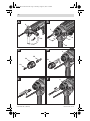
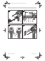
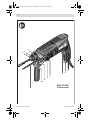
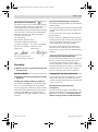
OBJ_DOKU-7132-001.fm Page 1 Thursday, August 30, 2007 5:09 PM
Robert Bosch GmbH
Power Tools Division
70745 Leinfelden-Echterdingen
www.bosch-pt.com
GBH Professional
1 619 929 736 (2007.08) T / 119
2-18 E | 2-18 RE
de
en
fr
es
pt
it
nl
Originalbetriebsanleitung
Original instructions
Notice originale
Manual original
Manual original
Istruzioni originali
Oorspronkelijke gebruiksaanwijzing
da
sv
no
fi
el
tr
Original brugsanvisning
Bruksanvisning i original
Original driftsinstruks
Alkuperäiset ohjeet
Πρωτότυπο οδηγιών χρήσης
Orijinal işletme talimat
OBJ_BUCH-427-001.book Page 3 Thursday, August 30, 2007 4:35 PM
3|
B
A
9
1
8
X
10
11
10
D
C
3
14
13
13
12
E
1 619 929 736 | (30.8.07)
F
3
Bosch Power Tools
OBJ_BUCH-427-001.book Page 4 Thursday, August 30, 2007 4:35 PM
4|
H
G
X
8
10
16
15
17
18
J
I
19
20
3
21
6
1 619 929 736 | (30.8.07)
Bosch Power Tools
OBJ_BUCH-427-001.book Page 5 Thursday, August 30, 2007 4:35 PM
5|
3
1
2
4
5
6
7
8
9
10
11
1 619 929 736 | (30.8.07)
GBH 2-18 RE
Professional
Bosch Power Tools
OBJ_BUCH-427-001.book Page 16 Thursday, August 30, 2007 4:35 PM
16 | English
4) Power tool use and care
a) Do not force the power tool. Use the correct power tool for your application. The
correct power tool will do the job better
and safer at the rate for which it was designed.
b) Do not use the power tool if the switch
does not turn it on and off. Any power tool
that cannot be controlled with the switch
is dangerous and must be repaired.
c) Disconnect the plug from the power
source and/or the battery pack from the
power tool before making any adjustments, changing accessories, or storing
power tools. Such preventive safety measures reduce the risk of starting the power
tool accidentally.
d) Store idle power tools out of the reach of
children and do not allow persons unfamiliar with the power tool or these instructions to operate the power tool.
Power tools are dangerous in the hands of
untrained users.
e) Maintain power tools. Check for misalignment or binding of moving parts, breakage of parts and any other condition that
may affect the power tool’s operation. If
damaged, have the power tool repaired
before use. Many accidents are caused by
poorly maintained power tools.
f) Keep cutting tools sharp and clean. Properly maintained cutting tools with sharp
cutting edges are less likely to bind and are
easier to control.
g) Use the power tool, accessories and tool
bits etc. in accordance with these instructions, taking into account the working
conditions and the work to be performed.
Use of the power tool for operations different from those intended could result in a
hazardous situation.
1 619 929 736 | (30.8.07)
5) Service
a) Have your power tool serviced by a qualified repair person using only identical replacement parts. This will ensure that the
safety of the power tool is maintained.
Machine-specific
Safety Warnings
f Wear hearing protection. Exposure to noise
can cause hearing loss.
f Always use the auxiliary handle supplied
with the machine. Loss of control can cause
personal injury.
f Use suitable detectors to determine if utility
lines are hidden in the work area or call the
local utility company for assistance. Contact
with electric lines can lead to fire and electric
shock. Damaging a gas line can lead to explosion. Penetrating a water line causes property
damage or may cause an electric shock.
f When working with the machine, always
hold it firmly with both hands and provide
for a secure stance. The power tool is guided
more secure with both hands.
f Secure the workpiece. A workpiece clamped
with clamping devices or in a vice is held more
secure than by hand.
f Do not work materials containing asbestos.
Asbestos is considered carcinogenic.
f Take protective measures when dust can develop during working that is harmful to one’s
health, combustible or explosive. Example:
Some dusts are regarded as carcinogenic.
Wear a dust mask and work with dust/chip extraction when connectable.
f Keep your workplace clean. Blends of materials are particularly dangerous. Dust from
light alloys can burn or explode.
Bosch Power Tools
OBJ_BUCH-427-001.book Page 17 Thursday, August 30, 2007 4:35 PM
English | 17
f Always wait until the machine has come to a
complete stop before placing it down. The
tool insert can jam and lead to loss of control
over the power tool.
f Never use the machine with a damaged cable. Do not touch the damaged cable and pull
the mains plug when the cable is damaged
while working. Damaged cables increase the
risk of an electric shock.
Functional Description
Read all safety warnings and all
instructions. Failure to follow the
warnings and instructions may result
in electric shock, fire and/or serious
injury.
While reading the operating instructions, unfold
the graphics page for the machine and leave it
open.
Intended Use
The machine is intended for hammer drilling in
concrete, brick and stone. It is also suitable for
drilling without impact in wood, metal, ceramic
and plastic. Machines with electronic control and
right/left rotation are also suitable for screwdriving.
Product Features
The numbering of the product features refers to
the illustration of the machine on the graphics
page.
1 SDS-plus tool holder
2 Dust protection cap
3
4
5
6
7
8
9
10
Locking sleeve
Lock-on button for On/Off switch
On/Off switch
Rotational direction switch (GBH 2-18 RE)
Selector switch for drilling/hammer drilling
Button for depth stop adjustment
Wing bolt for adjustment of auxiliary handle
Auxiliary handle
11
12
13
14
15
Depth stop
Securing screw for key type drill chuck*
Key type drill chuck*
SDS-plus adapter shank for drill chuck*
Extraction sleeve of the dust extraction
attachment*
16 Clamping screw for the dust extraction
attachment*
17 Depth stop of the dust extraction
attachment*
18 Telescopic pipe of the dust extraction
attachment*
19 Wing bolt of the dust extraction attachment*
20 Guide pipe of the dust extraction
attachment*
21 Universal bit holder with SDS-plus shank*
*The accessories illustrated or described are not
included as standard delivery.
Bosch Power Tools
1 619 929 736 | (30.8.07)
OBJ_BUCH-427-001.book Page 18 Thursday, August 30, 2007 4:35 PM
18 | English
Technical Data
Rotary Hammer
GBH 2-18 E
Professional
GBH 2-18 RE
Professional
Article number
3 611 B58 2..
3 611 B58 3..
Speed control
z
z
–
z
W
550
550
bpm
0 – 3960
0 – 3960
J
0 – 1.7
0 – 1.7
rpm
rpm
450 – 1550
–
450 – 1550
450 – 930
SDS-plus
SDS-plus
Spindle collar diameter
mm
43 (Euro-Norm)
43 (Euro-Norm)
Drilling diameter, max.:
– Concrete
– Steel
– Wood
mm
mm
mm
18
13
30
18
13
30
kg
2.0
2.0
/ II
/ II
Right/left rotation
Rated power input
Impact frequency at rated speed
Impact energy per stroke
Rated speed
– Right rotation
– Left rotation
Tool holder
Weight according to EPTA-Procedure 01/2003
Protection class
The values given are valid for nominal voltages [U] of 230/240 V. For lower voltage and models for specific countries,
these values can vary.
Please observe the article number on the type plate of your machine. The trade names of the individual machines
may vary.
Noise/Vibration Information
Measured values determined according to
EN 60745.
Typically the A-weighted noise levels of the product are: Sound pressure level 88 dB(A); Sound
power level 99 dB(A). Uncertainty K =3 dB.
Wear hearing protection!
Vibration total values (triax vector sum) determined according to EN 60745:
Hammer drilling into concrete: Vibration emission value ah =10 m/s2, Uncertainty K=1.5 m/s2.
The vibration emission level given in this information sheet has been measured in accordance with
a standardised test given in EN 60745 and may be
used to compare one tool with another. It may be
used for a preliminary assessment of exposure.
1 619 929 736 | (30.8.07)
The declared vibration emission level represents
the main applications of the tool. However if the
tool is used for different applications, with different accessories or poorly maintained, the vibration emission may differ. This may significantly
increase the exposure level over the total working period.
An estimation of the level of exposure to vibration should also take into account the times
when the tool is switched off or when it is running but not actually doing the job. This may significantly reduce the exposure level over the total
working period.
Identify additional safety measures to protect the
operator from the effects of vibration such as:
maintain the tool and the accessories, keep the
hands warm, organisation of work patterns.
Bosch Power Tools
OBJ_BUCH-427-001.book Page 19 Thursday, August 30, 2007 4:35 PM
English | 19
Declaration of Conformity
We declare under our sole responsibility that the
product described under “Technical Data” is in
conformity with the following standards or
standardization documents: EN 60745 according
to the provisions of the directives 2004/108/EC,
98/37/EC (until Dec. 28, 2009), 2006/42/EC
(from Dec. 29, 2009 on).
Technical file at:
Robert Bosch GmbH, PT/ESC,
D-70745 Leinfelden-Echterdingen
Dr. Egbert Schneider
Senior Vice President
Engineering
Dr. Eckerhard Strötgen
Head of Product
Certification
23.07.2007, Robert Bosch GmbH, Power Tools Division
D-70745 Leinfelden-Echterdingen
Adjusting the Drilling Depth (see figure B)
The required drilling depth X can be set with the
depth stop 11.
Press the button for the depth stop adjustment 8
and insert the depth stop into the auxiliary handle 10.
The knurled surface of the depth stop 11 must
face downward.
Insert the SDS-plus drilling tool to the stop into
the SDS-plus tool holder 1. Otherwise, the movability of the SDS-plus drilling tool can lead to incorrect adjustment of the drilling depth.
Pull out the depth stop until the distance between the tip of the drill bit and the tip of the
depth stop correspond with the desired drilling
depth X.
Selecting Drill Chucks and Tools
For hammer drilling, SDS-plus tools are required
that are inserted in the SDS-plus drill chuck.
f Before any work on the machine itself, pull
the mains plug.
For drilling without impact in wood, metal,
ceramic and plastic as well as for screwdriving,
tools without SDS-plus are used (e. g., drills with
cylindrical shank). For these tools, a keyless
chuck or a key type drill chuck are required.
Auxiliary Handle
Changing the Key Type Drill Chuck
f Operate your machine only with the auxiliary
handle 10.
To work with tools without SDS-plus (e.g., drills
with cylindrical shank), a suitable drill chuck
must be mounted (key type drill chuck or keyless
chuck, accessories).
Assembly
Rotating the Auxiliary Handle (see figure A)
The auxiliary handle 10 can be set to any position
for a secure and low-fatigue working posture.
Turn the wing bolt for adjustment of the auxiliary
handle 9 in anticlockwise direction and set the
auxiliary handle 10 to the required position.
Then tighten the wing bolt 9 again in clockwise
direction.
Bosch Power Tools
Mounting the Key Type Drill Chuck
(see figure C)
Screw the SDS-plus adapter shank 14 into a key
type drill chuck 13. Secure the key type drill chuck
13 with the securing screw 12. Please observe
that the securing screw has a left-hand thread.
1 619 929 736 | (30.8.07)
OBJ_BUCH-427-001.book Page 20 Thursday, August 30, 2007 4:35 PM
20 | English
Inserting the Key Type Drill Chuck
(see figure D)
Clean the shank end of the adapter shank and
apply a light coat of grease.
Insert the key type drill chuck with the adapter
shank into the tool holder with a turning motion
until it automatically locks.
Check the locking effect by pulling the key type
drill chuck.
Removing the Key Type Drill Chuck
Push the locking sleeve 3 toward the rear and
pull out the key type drill chuck 13.
Changing the Tool
The dust protection cap 2 largely prevents the
entry of drilling dust into the tool holder during
operation. When inserting the tool, take care that
the dust protection cap 2 is not damaged.
f A damaged dust protection cap should be
changed immediately. We recommend having this carried out by an after-sales service.
Inserting SDS-plus Drilling Tools (see figure E)
The SDS-plus drill chuck allows for simple and
convenient changing of drilling tools without the
use of additional tools.
Clean and lightly grease the shank end of the tool.
Insert the tool in a twisting manner into the tool
holder until it latches itself.
Check the latching by pulling the tool.
As a requirement of the system, the SDS-plus
drilling tool can move freely. This causes a certain radial run-out at no-load, which has no effect
on the accuracy of the drill hole, as the drill bit
centres itself upon drilling.
Removing SDS-plus Drilling Tools (see figure F)
Push back the locking sleeve 3 and remove the
tool.
1 619 929 736 | (30.8.07)
Inserting Drilling Tools without SDS-plus
Note: Do not use tools without SDS-plus for hammer drilling! Tools without SDS-plus and their
drill chucks are damaged by hammer drilling.
Insert a key type drill chuck 13 (see “Changing
the Key Type Drill Chuck”, page 19).
Open the key type drill chuck 13 by turning until
the tool can be inserted. Insert the tool.
Insert the chuck key into the corresponding holes
of the key type drill chuck 13 and clamp the tool
uniformly.
Set the selector switch 7 to the “Drilling” symbol.
Removing Drilling Tools without SDS-plus
Turn the sleeve of the key type drill chuck 13 with
the drill chuck key in anticlockwise direction until
the drilling tool can be removed.
Dust Extraction with the Dust Extraction
Attachment (Accessory)
Mounting the Dust Extraction Attachment
(see figure G)
For dust extraction, the dust extraction attachment (accessory) is required. When drilling, the
dust extraction attachment retracts so that the
attachment head is always close to the surface at
the drill hole.
Press the button for depth stop adjustment 8
and remove the depth stop 11. Press button 8
again and insert the dust extraction attachment
into the auxiliary handle 10 from the front.
Connect an extraction hose (diameter 19 mm,
accessory) to the extraction sleeve 15 of the dust
extraction attachment.
The vacuum cleaner must be suitable for the
material being worked.
When vacuuming dry dust that is especially detrimental to health or carcinogenic, use a special
vacuum cleaner.
Bosch Power Tools
OBJ_BUCH-427-001.book Page 21 Thursday, August 30, 2007 4:35 PM
English | 21
Adjusting the Drilling Depth on the Dust
Extraction Attachment (see figure H)
The required drilling depth X can also be adjusted when the dust extraction attachment is
mounted.
Insert the SDS-plus drilling tool to the stop into
the SDS-plus tool holder 1. Otherwise, the movability of the SDS-plus drilling tool can lead to incorrect adjustment of the drilling depth.
Loosen the wing bolt 19 on the dust extraction
attachment.
Setting the Operating Mode
With the selector switch for drilling/hammer
drilling 7, the operating mode of the machine is
selected.
Note: Change the operating mode only when the
machine is switched off! Otherwise, the machine
can be damaged.
To change the operating mode, turn the selector
switch for “drilling/hammer drilling” 7 to the
requested position.
Without switching the power tool on, apply it
firmly to the drilling location. The SDS-plus drilling tool must face against the surface.
Position for hammer drilling in
concrete or stone
Position the the guide pipe 20 of the dust extraction attachment in its holding fixture in such a
manner that the head of the dust extraction attachment faces against the surface to be drilled.
Do not slide the guide pipe 20 further over the telescopic pipe 18 of the dust extraction attachment
than required, so that as much as possible of the
scale 18 on the telescopic pipe remains visible.
Position for drilling without impact
in wood, metal, ceramic and plastic
as well as for screwdriving
Retighten the wing bolt 19 again. Loosen the
clamping screw 16 on the depth stop of the dust
extraction attachment.
Move the depth stop 17 on the telescopic pipe 18
in such a manner that the clearance X shown in
the figure corresponds with the required drilling
depth.
Tighten the clamping screw 16 in this position.
Operation
Starting Operation
f Observe correct mains voltage! The voltage
of the power source must agree with the
voltage specified on the nameplate of the
machine. Power tools marked with 230 V can
also be operated with 220 V.
Bosch Power Tools
Reversing the Rotational Direction
(GBH 2-18 RE) (see figure I)
The rotational direction switch 6 is used to reverse the rotational direction of the machine.
However, this is not possible with the On/Off
switch 5 actuated.
Right rotation: Push the rotational direction
switch 6 rightward to the stop.
Left rotation: Push the rotational direction
switch 6 leftward to the stop.
For hammer drilling and drilling, always set the
direction of rotation to right rotation.
Switching On and Off
To start the machine, press the On/Off switch 5.
To lock the On/Off switch, keep it pressed and
additionally push the lock-on button 4.
To switch off the machine, release the On/Off
switch 5. When the On/Off switch 5 is locked,
press it first and then release it.
Setting the Speed/Impact Rate
The speed/impact rate of the switched on power
tool can be variably adjusted, depending on how
far the On/Off switch 5 is pressed.
Light pressure on the On/Off switch 5 results in
low speed/impact rate. Further pressure on the
switch increases the speed/impact rate.
1 619 929 736 | (30.8.07)
OBJ_BUCH-427-001.book Page 22 Thursday, August 30, 2007 4:35 PM
22 | English
Safety Clutch
f If the tool insert becomes caught or jammed,
the drive to the drill spindle is interrupted.
Because of the forces that occur, always
hold the power tool firmly with both hands
and provide for a secure stance.
f If the power tool jams, switch the machine
off and loosen the tool insert. When switching the machine on with the drilling tool
jammed, high reaction torques can occur.
Working Advice
Inserting Screwdriver Bits (see figure J)
f Apply the power tool to the screw/nut only
when it is switched off. Rotating tool inserts
can slip off.
To work with screwdriver bits, a universal bit holder 21 with SDS-plus shank (accessory) is required.
Clean the shank end of the adapter shank and
apply a light coat of grease.
Insert the universal bit holder with a turning
motion into the tool holder until it automatically
locks.
Check the locking effect by pulling the universal
bit holder.
Insert a screwdriver bit into the universal bit
holder. Use only screwdriver bits that match the
screw head.
To remove the universal bit holder, pull the locking sleeve 3 toward the rear and remove the universal bit holder 21 out of the tool holder.
Maintenance and Service
Maintenance and Cleaning
f Before any work on the machine itself, pull
the mains plug.
f For safe and proper working, always keep
the machine and ventilation slots clean.
f A damaged dust protection cap should be
changed immediately. We recommend having this carried out by an after-sales service.
Clean the tool holder 1 each time after using.
1 619 929 736 | (30.8.07)
WARNING! Important instructions for connecting a new 3-pin plug to the 2-wire cable.
The wires in the cable are coloured according to
the following code:
Do not connect the blue or brown wire to the
earth terminal of the plug.
Important: If for any reason the moulded plug is
removed from the cable of this power tool, it
must be disposed of safely.
If the machine should fail despite the care taken
in manufacturing and testing procedures, repair
should be carried out by an after-sales service
centre for Bosch power tools.
In all correspondence and spare parts order,
please always include the 10-digit article number
given on the type plate of the machine.
After-sales service and customer
assistance
Our after-sales service responds to your questions concerning maintenance and repair of your
product as well as spare parts. Exploded views
and information on spare parts can also be found
under:
www.bosch-pt.com
Our customer consultants answer your questions
concerning best buy, application and adjustment
of products and accessories.
Great Britain
Robert Bosch Ltd. (B.S.C.)
P.O. Box 98
Broadwater Park
North Orbital Road
Denham
Uxbridge
UB 9 5HJ
Tel. Service: +44 (0844) 736 0109
Fax: +44 (0844) 736 0146
E-Mail: [email protected]
Bosch Power Tools
OBJ_BUCH-427-001.book Page 118 Thursday, August 30, 2007 4:35 PM
118 |
1 617 000 132
SDS-plus
1 608 571 062
Ø 1,5 – 13 mm
2 602 025 102
1 613 001 010
1 607 950 045
2 607 000 207
1 607 000 173
2 605 438 524
1 619 929 736 | (30.8.07)
Bosch Power Tools