1
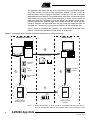
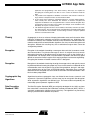
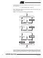
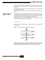
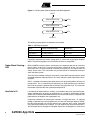
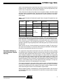
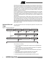
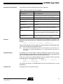
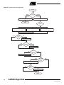
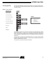
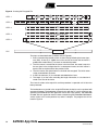
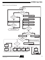
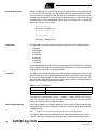
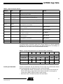
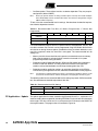
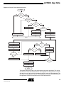
AVR230: DES Bootloader
Features
• Fits All AVR Microcontrollers with Bootloader Capabilities
• Enables Secure Transfer of Compiled Software or Sensitive Data to Any AVR with
Bootloader Capabilities
8-bit
Microcontroller
• Includes Easy To Use, Configurable Example Applications
•
•
•
•
•
– Encrypting Binary Files and Data
– Creating Target Bootloaders
– Downloading Encrypted Files to Target
Encryption Algorithm Follows Data Encryption Standard (DES)
Triple Data Encryption Standard (3DES) for Increased Security
DES Bootloader Fits Into 2-KB on All AVR Devices
3DES Bootloader Fits Into 2-KB on All AVR Devices, Except ATmega128
Typical Update Times of a 16-KB Application, Including Transfer of Data, Decryption
and Programming of Flash Memory
– DES, 115200 Bauds, 16 MHz Target Frequency: 20 Seconds
– 3DES, 115200 Bauds, 16 MHz Target Frequency: 50 Seconds
Application Note
Introduction
This application note describes how firmware can be updated securely on AVR microcontrollers with bootloader capabilities. The method includes using the Data
Encryption Standard (DES) to encrypt the firmware. This application note also supports the Triple Data Encryption Standard (3DES).
Electronic designs including a microcontroller always need to be equipped with a firmware, be it a portable music player, a hairdryer or a sewing machine. As many
electronic designs evolve rapidly there is a growing need for being able to update
products, which have already been shipped or sold. It may prove difficult to make
changes to the hardware, especially if the product has already reached the end customer. But the firmware can easily be updated on products based on Flash
microcontrollers, such as the AVR family.
Many AVR microcontrollers are configured such that it is possible to create a bootloader able to receive firmware updates and to reprogram the Flash memory on
demand. The program memory space is divided in two sections: the Bootloader Section (BLS) and the Application Section. Both sections have dedicated lock bits for read
and write protection such that a bootloader code can be secured in the BLS while still
being able to update the code in the application area. Hence, the update algorithm in
the BLS can easily be secured against outside access.
The problem remains with the firmware, which typically is not secured before it has
been programmed into Flash memory and lock bits have been set. This means that if
the firmware needs to be updated in the field, it will be open for unauthorized access
from the moment it leaves the programming bench or manufacturer’s premises.
Rev. 2541D–AVR–04/05
This application note shows how data to be transferred to Flash and EEPROM memories can be secured at all times by using cryptographic methods. The idea is to encrypt
the data before it leaves the programming bench and decrypt it only after it has been
downloaded into the target AVR. This procedure does not prevent unauthorized copying
of the firmware, but the copy (and of course the original) is virtually useless without the
proper decryption keys. Decryption keys are only stored in one location outside the programming environment: inside the target AVR. Provided that lock bits are set, the keys
cannot be read from the target AVR. Also, the keys cannot be regenerated from the
encrypted data. The only way to gain access to the data is by using the proper keys.
Figure 1 shows an example of how a product is first manufactured, loaded with initial
firmware, sold and later updated with a new revision of the firmware.
Figure 1. An Example of the Production and Update Procedure of an AVR-based Design
MANUFACTURER
THIRD PARTY
3
FIRMWARE UPDATES
FIRMWARE
(INITIAL)
1
BOOTLOADER
4
FIRMWARE
(UPDATE)
DECRYPTION
KEYS
2
PRODUCT SOLD
PRODUCT BEING
MANUFACTURED
Notes:
2
PRODUCT BEING
UPDATED
1. During manufacturing, the microcontroller is first equipped with bootloader, decryption keys and application firmware. The bootloader takes care of receiving the actual
AVR230 App Note
2541D–AVR–04/05
AVR230 App Note
application and programming it into Flash memory, while keys are required for
decrypting the incoming data. Lock bits are set to secure the firmware inside the
AVR.
2. The product is then shipped to a distributor or sold to the end customer. Lock bit settings continue to keep the firmware secured inside the AVR.
3. A new release of the firmware is completed and there is a need to update products,
which already have been distributed. The firmware is therefore encrypted and
shipped to the distributor. The encrypted firmware is useless without decryption keys
and therefore even local copies of the software (for example, on the hard drive of the
distributor) do not pose a security hazard.
4. The distributor upgrades all units in stock and those returned by customers (for example, during repairs). The encrypted firmware is downloaded to the AVR and decrypted
only once inside the microcontroller. Lock bit settings continue to keep the updated
firmware secured inside the AVR.
Theory
Cryptography is the art or science of keeping information secret and is based on either
hiding the cryptographic method or securing the cryptographic key. Algorithms only
based on the secrecy of the method used are mainly of historical interest and do not
meet the needs of the real world. Modern algorithms use a key to control encryption and
decryption. Without the matching key, the scrambled message or data cannot be
arranged into plaintext.
Encryption
Encryption is the method of encoding a message or data such that its contents are hidden from outsiders. The plaintext message or data in its original form may contain
information the author or distributor wants to keep secret, such as the firmware of a
microcontroller. For example, when a microcontroller is updated in the field it may prove
difficult to secure the firmware against illicit copying attempts and reverse engineering.
Encrypting the firmware will render it useless until it is decrypted.
Decryption
Decryption is the method of retrieving the original message or data and typically cannot
be performed without knowing the proper key. Keys can be stored in a bootloader of the
microcontroller such that the device can receive encrypted data, decrypt it and reprogram selected parts of the Flash or EEPROM memory. Decryption keys cannot be
retrieved from the encrypted data and cannot be read from AVR microcontrollers if lock
bits have been programmed.
Cryptographic Key
Algorithms
Algorithms based on cryptographic keys are divided in two classes; symmetric and
asymmetric. Symmetric algorithms use the same key for encryption and decryption
while asymmetric algorithms use different keys. The most studied and probably the
most widely spread symmetric algorithm is DES.
Data Encryption
Standard – DES
The Data Encryption Standard (DES) was originally developed in the 1970’s and was
later turned into a standard by the US National Institute of Standards (NIST). DES is a
symmetric cryptographic algorithm using a 56-bit key. The algorithm has proved very
strong in practice and has outlived many others.
3
2541D–AVR–04/05
The DES algorithm uses a 56-bit encryption key, meaning that the number of possible
key combinations is:
256 = 72,057,594,037,927,936 = 7.206 x 10¹⁶
DES is a block cipher, operating on blocks of 64 bits of data. Each input block is processed as illustrated in Figure 2.
Figure 2. The Encryption Flow According to the DES Algorithm
INPUT
64
INITIAL PERMUTATION
32
32
K1
L0
+
+
R0
48
32
32
f
32
L1 = R0
+
K2
R1
+
f
L15 = R14
+
K16
R15
+
f
R16
L16 = R15
INVERSE INITIAL PERMUTATION
64
OUTPUT
Figure 2 illustrates how a single block of data is being encrypted. First, the order of the
input bits is changed according to the permutation function. The low 32 bits (R0) are then
processed separately from the high 32 bits (L0). There are 16 process steps, each step
4
AVR230 App Note
2541D–AVR–04/05
AVR230 App Note
using a different subset (Kn) of the encryption key (only steps 1, 2 and 16 are illustrated
in Figure 2). Finally, the bit order is changed inversely with respect to the initial permutation function.
The decryption algorithm is the same as the encryption algorithm; only the sequence of
the key subsets Kn is reversed.
The DES algorithm is described in more details in the DES standard (see References
section).
Triple Data Encryption
Standard – 3DES
Triple Data Encryption Standard (3DES) is based on using DES three times, thus
increasing the key length from 56 to 168 bits. 3DES is very much stronger than DES but
rather slow for real-time applications, as compared to some newer algorithms. For this
application note, timing is not critical and 3DES may be considered apt.
The 3DES algorithm uses three 56-bit encryption keys. The number of possible key
combinations therefore increases (wrt single DES) to:
2168 = 3.741 x 1050
3DES is based on using DES three times, as defined in ANSI x9.52. The encryption flow
is illustrated below.
Figure 3. The Encryption Flow According to the 3DES Algorithm
INPUT
DES ENCRYPTION
KEY1
DES DECRYPTION
KEY2
DES ENCRYPTION
KEY3
OUTPUT
During encryption, the input is first encrypted with the first key, then decrypted with the
second key and finally encrypted with the third key. During decryption, the key sequence
and encryption/decryption block sequence is reversed, as illustrated in Figure 4.
5
2541D–AVR–04/05
Figure 4. The Decryption Flow According to the 3DES Algorithm
INPUT
DES DECRYPTION
KEY3
DES ENCRYPTION
KEY2
DES DECRYPTION
KEY1
OUTPUT
The following keying options are defined in the standard.
Table 1. 3DES Keying Options
Option
Number of Independent Keys
Related Keys
Keying Option 1
Three (KEY1, KEY2 and KEY3)
(None)
Keying Option 2
Two (KEY1 and KEY2)
KEY3 = KEY1
Keying Option 3
One (KEY1)
KEY1 = KEY2 = KEY3
It should be noted that only the first keying option (1) utilizes the full encryption length of
3DES. The third keying option (3) is essentially the same as single DES.
Cipher Block Chaining –
CBC
DES and 3DES are block ciphers, meaning that the algorithm operates on fixed-size
blocks of data. A 56-bit key is used to encrypt data in blocks of 64 bits. For a known
input block and a constant (although, unknown) encryption key, the output block will
always be the same. This information may provide useful for somebody wanting to
attack the cipher system.
There are some methods commonly used which cause identical plaintext blocks being
encrypted to different ciphertext blocks. One such method is called Cipher Block Chaining (CBC).
CBC is a method of connecting the cipher blocks such that leading blocks influence all
trailing blocks. This is achieved by first performing an XOR operation on the plaintext
block and the previous ciphertext block and then encrypting the result. This increases
the number of plaintext bits one ciphertext bit depends on.
How Safe Is It?
It is important to understand that, in theory, it is possible to break any key-based cryptographic method simply by testing all possible keys in a sequence. Considering an ideal
system that cannot be broken down otherwise, the level of data security is exponentially
proportional to the length of the cryptographic key.
A common method for illicit decryption attempts is using brute force, i.e. stepping
through all possible keys and trying them one at a time until the output appears intelligible. No human operator can manually take on such a process, but it can be automated
using specialized software or hardware. This yet requires that the human operator is
able to model how to distinguish intelligible output from unintelligible. In brute force
6
AVR230 App Note
2541D–AVR–04/05
AVR230 App Note
attacks, the computing power required to break the key increases exponentially with the
length of the key. Since the average computing power increases exponentially over
time, it is only a matter of time until any key can be broken.
Table 2 illustrates the effect of key length versus encryption strength. It should be noted
that these figures are guidelines only, and that there are large variations in many of the
estimates. The information has been gathered from sources mentioned in the References section.
Table 2. Time Estimates for Breaking Encryption Versus Length of Encryption Key (see
References)
Key Length
Example
Individuals, Small
Companies
Organized Criminals, Major Companies,
Governments
Standard PC
Linked PCs
32 bits
Minutes … Hours
40 bits
Days … Weeks
56 bits
DES
64 bits
Virtually
Unbreakable
80 bits
128 bits
168 bits
3DES
Special Hardware
Minutes … Hours
Weeks … Months
Hours … Days
Very Long
Short
Long
Virtually
Unbreakable
Virtually
Unbreakable
Another attack method is that of targeting the hardware, not the encrypted information.
In this application note, the hardware is secured by Atmel’s Flash-based AVR microcontroller architecture. A DES/3DES bootloader including decryption keys is loaded into the
Flash and the memory is then protected using lock bits. The firmware can now be
updated in the field using encrypted patches but the decryption keys cannot be retrieved
from the AVR.
When lock bits are set, all write and external read access is denied. The only way to
gain access to the memory is to erase the device. Doing so, bootloader and decryption
keys will be destroyed before the lock bits are erased.
Recommendations on
How to Improve System
Security
This application note presents techniques that can be used when securing a design
from outside access. Although no design can ever be fully secured it can be constructed
such that the effort required to break the security is as high as possible. There is a significant difference between an unsecured design that a person with basic engineering
skills can duplicate and a design that only few, highly skilled intruders can break. In the
first example, the design is easily copied and even reverse engineered, violating the
intellectual property of the manufacturer and jeopardizing the market potential for the
design. In the second example, the effort required to break the design is so high that
most intruders simply focus on developing their own products.
There is only one general rule on how to build a secure system: it should be designed to
be as difficult to break as possible. Any mechanism that can be used to circumvent
security will be tried during a break attempt. Even exotic situations should be considered. A few examples of what must be considered are given below.
What will happen if power is removed during a firmware update? What is the state of the
microcontroller when power is restored back? Are lock bits and reset vectors set properly at all times?
7
2541D–AVR–04/05
Are there any assumptions that can be made on what cleartext data will look like? In
order for DES to be broken by brute force methods, there must be a pattern to look for.
The attacker cannot simply try all key combinations and watch the output, looking for
intelligible firmware. The attack software will have to be configured to search for a
known pattern, such as interrupt vectors at the start of program memory, memory areas
padded with zero or one, and so on.
Is there any feedback that can be derived from the decryption process? Any such feedback can help the attacker in constructing a brute force attack platform. For example, if
the decryption algorithm inside the bootloader would give an OK/Not OK type of signal
for each block processed then this signal could easily be routed as feedback to the
attack platform.
Should encrypted frames be sent in another order? If the first frame sent to the bootloader always includes the first block of the encrypted file then the attacker can make
some assumptions from this. For example, it can be assumed the first frame maps program data starting from address zero and that it contains the interrupt vector table. This
information helps the attacker to refine the key search. To increase the security of the
system, send the frames in random order (the decrypted frames will be mapped to their
proper address, anyhow).
Implementation and
Usage
This section describes how to use and configure the applications. The process is illustrated in Figure 5.
Figure 5. Overview of Project Flow
Application Note
Miscellaneous Editor
Application Builder
EEPROM
Data
Firmware
Text Editor/GenTemp
Configuration
File
Create
Bootloader
Source
Header
File
IAR Embedded Workbench
Bootloader
Key File
Encrypted
Firmware
Update
Frames
Target AVR
The main steps are as follows:
1. Create an application for the target AVR. If required, create an EEPROM layout
in a separate file.
2. Create a configuration file with project dependent information. The application
called GenTemp can be used for creating a file frame.
3. Run the application called Create. This will create the header file, key file and the
encrypted file.
4. Using IAR EW, configure and build the bootloader for the target AVR.
5. Download bootloader to target AVR and set lock bits & fuse bits.
6. Now the encrypted firmware may be downloaded to the AVR at any time.
8
AVR230 App Note
2541D–AVR–04/05
AVR230 App Note
The procedure is discussed in more details below.
Configuration File
The configuration file contains a list of parameters, which are used to configure the
project. The parameters are described in Table 3.
Table 3. Summary of Configuration File Options
Parameter
Description
Default
Required
PAGE_SIZE
Size of AVR Flash page in decimal bytes. This figure is
part-dependent. Please see datasheet.
N/A
Yes
KEY1
First encryption key in hexadecimal. Should be eight
random bytes, where every 8th bit is used as odd-parity
bit
None: No encryption
No, but strongly
recommended
KEY2
Second encryption key. Similar to first key, but used in
two-key 3DES. If omitted, single DES encryption will be
used
None: use single DES
No, but recommended
KEY3
Third encryption key. Similar to first key, but only used
in three-key 3DES. If omitted, single or two-key DES
encryption will be used
None: use single or two-key
DES
No
INITIAL_VECTOR
Used for chaining cipher blocks. Should be eight
random bytes in hexadecimal
0000000000000000
No, but strongly
recommended
SIGNATURE
Frame validation data. This can be any four bytes, but it
is recommended the values are chosen on random
00000000
Yes
ENABLE_CRC
Enable CRC checking: Yes or No. If enabled, all
application section will be overwritten and the
application must pass a CRC check before it is allowed
to start
No
No, but recommended
MEM_SIZE
Size of application section in target AVR (in decimal
bytes)
None
Yes, if CRC is used
Note:
The DES algorithm uses 56-bit keys, but the keys are given 8-byte (64 bits) wide in the configuration file. This is because every
8th bit is used as an odd-parity bit.
The configuration file can be given any valid file name (the name is later given as a
parameter to the application that will create the project files). Below is a sample configuration file for the ATmega16.
PAGE_SIZE
= 128
MEM_SIZE
= 14336
KEY1
= 0123456789ABCDEF
KEY2
= FEDCBA9876543210
KEY3
= 89ABCDEF01234567
INITIAL_VECTOR
= 0011223344556677
SIGNATURE
= 89ABCDEF
ENABLE_CRC
= YES
Some of the parameters cannot be set without specific knowledge of the target AVR.
Table 4 summarizes the features of some present AVR microcontrollers with bootloader
functionality. For devices not present in this table, please refer to the datasheet of the
device.
9
2541D–AVR–04/05
Table 4. AVR Feature Summary
M8
M8515
Flash Size, bytes
8K
Flash Page Size, bytes
64
M8535
M16
M32
M64
M128
32K
64K
128K
128
128
BLS (max), bytes
2048
256
256
512
4096
32
16
MEM_SIZE, bytes
6144
14336
PAGE_SIZE, bytes
64
PC Application –
GenTemp
M169
16K
Flash Pages
BLS Pages
M162
8192
32
28672
128
57344
122880
256
This application note includes a small PC application, which will generate a template for
the configuration file. The application generates random encryption keys and initial vectors, leaving other parameters for the user to be filled in (such as the Flash page size). It
is recommended to always start with creating a template using this application, as this
procedure guarantees truly random encryption keys and removes human predictability.
The application is used as follows:
GenTemp FileName.Ext
… where FileName.Ext is the name of the configuration file, which will be created. After
the file has been generated it can be edited using any plain text editor of choice.
PC Application – Create
This PC application has been created using Microsoft® Visual C++, version 6.0. It reads
information from the configuration file and generates key and header files for the bootloader. It is also used for encrypting the firmware. Typically, the application is run at
least twice; first, to generate key and header files for the bootloader and, second, when
a new firmware is encrypted.
Note:
It is very important that the same encryption information (configuration file) is used when
generating project files and when encoding the firmware. Otherwise, the bootloader may
not have the correct set of encryption keys and cannot decrypt the data.
It should also be noted that it is possible to use the information in the configuration file to
decrypt the encrypted firmware. Hence, the configuration file must be kept safe at all
times and should not be modified after it has been used for the first time.
10
AVR230 App Note
2541D–AVR–04/05
AVR230 App Note
Command Line Arguments
The application accepts the following command line arguments.
Table 5. Summary of Command Line Arguments
First Run
Argument
Description
-c <filename.ext>
Path to configuration file
-d
If set, contents of each Flash page is deleted before writing. Else,
previous data will be preserved if not specifically written to.
-e <filename.ext>
Path to EEPROM file (data that goes into EEPROM)
-f <filename.ext>
Path to Flash file (code that goes into Application Section)
-h <filename.ext>
Name of output header file. This file must later be included with the
bootloader.
-k <filename.ext>
Name of output key file. This file must later be included with the
bootloader.
-l [BLB12] [BLB11] [BLB02]
[BLB01]
Lock bits to set. These lock bits are set after all data has been
transferred and before control is transferred to the updated
application.
-n
Nonsense. Add random number of nonsense records to encrypted
file. As nonsense records are ignored by the bootloader, this setting
does not affect the application, only the predictability of the output
file.
-o <filename.ext>
Output file name. This is the encrypted file that may be distributed
and sent to the target when it needs to be updated.
In the first run, typically, only key and header files for the bootloader are generated. The
generation of key and header files is requested using command line arguments. For
example:
Create –c Config.txt –h BootLdr.h –k DESKeys.inc
The key and header files must be copied to the project directory of the bootloader application and be included into the bootloader code.
Note:
Subsequent Runs
Please note that the bootloader project files are preconfigured to use the file names mentioned above, i.e. BootLdr.h and DESKeys.inc. It is recommended these file names are
not changed.
In subsequent runs, the application is used for encoding the firmware. Prior to encryption, the source file must be compiled, assembled and linked into one code segment file
and/or one EEPROM segment file. Files must be of type Intel hex.
A file name is given at the command prompt and an encrypted file will be generated
according to data in the configuration file. For example:
Create –c Config.txt –e EEPROM.hex –f Flash.hex –o
Update.enc –l BLB11 BLB12
The application software and EEPROM data files will be combined into a single
encrypted file.
Program Flow
The program flow is illustrated in Figure 6.
11
2541D–AVR–04/05
Figure 6. Program Flow of PC Application
Create
NONE
OTHER
Command
Line Args?
Give Instructions
Read Configuration File
Done
How Many
Keys?
ONE
DES Keying Option 3: 56 bits
(all three keys are equal)
NO
THREE
TWO
Key File
Name
Given?
DES Keying Option 2: 112 bits
(keys 1 and 3 are equal)
DES Keying Option 1: 168 bits
(all three keys are independent)
YES
Create Key File
NO
Header
File Name
Given?
YES
Create Header File
YES
Flash
File Name
Given?
NO
Include Flash File In Encryption
YES
EEPROM
File Name
Given?
NO
Include EEPROM File In Encryption
NO
Output
File Name
Given?
YES
Create Encrypted File
Done
12
AVR230 App Note
2541D–AVR–04/05
AVR230 App Note
The Encrypted File
The Flash and EEPROM file are encrypted and stored in one target file. Before encryption, however, data is organiszed into records. There are seven types of records, as
illustrated in Figure 7.
Figure 7. Types of Records
RECORD TYPE
LAYOUT
END OF FRAME
0
FLASH PAGE ERASE
1
AB
NB
FLASH PAGE PREPARE
2
AB
NB
FLASH PAGE DATA
3
AB
NB
FLASH PAGE PROGRAM
4
AB
NB
EEPROM SECTION DATA
5
AB
NB
LOCK BITS
6 L
RESET
7
NONSENSE
N
LEGEND
(VARIABLE LENGTH)
AB
ADDRESS IN BYTES
NB
LENGTH IN BYTES
L
LOCK BITS
R
RANDOM DATA
N
ANY VALUE IN 8...255
(VARIABLE LENGTH)
R
R
The record type is given as the first byte in the record. The application data is broken
down to record types 1, 2, 3 and 4 (i.e., erase, prepare, load and write buffer page to
Flash). The data for the EEPROM section is formatted into record type 5. Lock bits are
sent in record type 6. Record types 0 and 7 are for ending a frame and transmission,
respectively.
All other records, i.e. those with a record identifier above 7, are of type nonsense. When
this option is enabled (see Create tool), a random number of nonsense records will be
placed at random locations in the file.
The output file is created as illustrated in the Figure 8.
13
2541D–AVR–04/05
Figure 8. Creating the Encrypted File
STEP 1
STEP 2
SIG
INITIAL VECTOR
RECORD
CIPHER BLOCK
CIPHER BLOCK
RECORD
RECORD
CIPHER BLOCK
RECORD
CIPHER BLOCK
Z
F
CIPHER BLOCK
STEP 3
CHAINED AND ENCRYPTED DATA
STEP 4
CHAINED AND ENCRYPTED DATA
C
CHAINED AND ENCRYPTED DATA
C
STEP 5
L
FILE
FRAME
The steps are described below (numbers refer to Figure 8).
1. Data is formatted into records, which are then lined up following the frame signature (SIG). A zero (Z) is added to mark the end of the frame and the frame is
padded with random data (F) to create an even 64-bit product.
2. The initial vector is attached to the frame. In the first frame, the vector is equal to
the one given in the configuration file. In subsequent frames, the initial vector is
equal to the last cipher block of the previous frame.
3. The initial vector and cipher blocks are chained and encrypted. The initial vector
is then removed from the frame.
4. A CRC-16 checksum (C) is calculated and added to the frame.
5. The length (L) of the frame, excluding the length information, is calculated and
saved at the start of the frame.
The frame is written to the output file and the procedure is repeated until all data has
been processed.
Bootloader
14
The bootloader must reside in the target AVR before the device can be updated with
encrypted firmware. The bootloader communicates with the PC and is capable of programming the EEPROM and the application area of the Flash memory. The bootloader
included with this application note has been created using IAR Embedded Workbench,
version 2.28a, but it can be ported to any other C compiler. The program flow is illustrated in Figure 9.
AVR230 App Note
2541D–AVR–04/05
AVR230 App Note
Figure 9. Program Flow of AVR Bootloader
Bootldr
NO
YES
Switch SW7
Pressed?
Load Initial Vector for CBC
NO
CRC Check
Enabled?
Read Frame Size (Two Characters)
YES
Calculate CRC of Appl. Section
NO
Read Character, Store in RAM
Application
CRC Valid?
Update Frame CRC Counter
YES
NO
End of
Frame?
Jump to Application
YES
YES
Frame CRC
Valid?
Decrypt and Unchain
YES
ERASE
NO
Send Frame CRC Error
NO
Signature
Valid?
NOTE WELL: IF CRC IS VALID, FRAME IS
DECRYPTED. ANY INFORMATION SENT
ON DECRYPTION STATUS OTHER THAN
OK MAY BE USED IN AN ATTACK ATTEMPT
Ignore Frame BUT Send OK
Type?
Erase
Page
PREPARE
Prepare
Page
DATA
Load
Data
PROGRAM
Write
Page
EEPROM
Write
EEPROM
LOCKBITS
Write
Lock Bits
NONSENSE
Do
Nothing
RESET
EOF
Set Initial
Vector
Send OK
15
2541D–AVR–04/05
Key and Header Files
Before the bootloader can be compiled, there are some parameters that need to be set
up. To start with, the encryption key and target header files generated by the PC application Create must be copied to the directory of the bootloader so that they may be
included in the bootloader. The files will be included when they are referred to with the
#include directive inside the bootloader source code. For example (this is a copy of the
beginning of the des.c source code):
...
#include "des.h"
#include "bootldr.h"
#include "loader.h"
#if KEY_COUNT > 0
#include "deskeys.inc"
...
Project Files
This application note comes with device specific project files for the following devices:
•
ATmega8
•
ATmega8515
•
ATmega16
•
ATmega169
•
ATmega32
•
ATmega64
•
ATmega128
Use the predefined project files with the corresponding AVR. For AVR devices not listed,
use the project file for a device that matches the target device as close as possible and
modify the following sections, as described below.
Linker File
The IAR compiler requires a modified linker file because the bootloader will reside in the
upper memory area, i.e. in the Bootloader Section (BLS). Linker files have an extension
of .xcl and are distributed with the IAR compiler for each AVR device separately. This
application note comes with two linker files, one of which should be used (depending on
the set-up of the choice of interrupt vector table).
Table 6. Linker File Selection
Linker File Name
Use With
bootldr.xcl
All AVR devices, interrupt vector table allocated for code (saves memory)
bootldr_interrupts.xcl
All AVR devices, interrupt vector table padded with RETI
The linker file is defined under “Project” – “Options”, category “XLINK”, tab “Include”,
field “XCL file name”. Note that the linker file is already set up in the device specific
project files that come with this application note.
Other Compiler Settings
In the Project window, set Targets to Release. This will create no debug code and minimize overall code size of the bootloader. Code size is critical for AVR devices with only
2-KB Boot Section.
Note:
If Target is not set to Release, the project will not necessarily link properly.
The following settings need to be defined in the dialog window found under “Project” –
“Options”. Note that all settings are already defined in the device specific project files.
16
AVR230 App Note
2541D–AVR–04/05
AVR230 App Note
Table 7. Required Compiler Settings
Category
Tab
Set to
Example
General
Target
Set “Processor configuration” to match target AVR
-cpu=m8, AT90mega8
Set “Memory model” to Small
Uncheck “Configure system using dialogs (not in .XCL file)”
AAVR
XLINK
Library
Configuration
Check “Enable bit definitions in I/O-include files”
Preprocessor
Define symbol “INCLUDE_FILE” to match target AVR
INCLUDE_FILE=”iom8.h”
Define symbol SPMREG to match target
SPMREG=SPMCR
Output
Define output file format such that the file can programmed
to the target. Set to Intel-standard
#define
Define symbol BOOT_SIZE to match target bootloader
section. In hex bytes
BOOT_SIZE=800
Define symbol FLASH_SIZE to match Flash size of target.
In hex bytes
FLASH_SIZE=2000
Define symbol IVT_SIZE to match size of target interrupt
vector table. In hex bytes
IVT_SIZE=26
Define symbol RAM_SIZE to match amount of RAM on
target. In hex bytes
RAM_SIZE=400
Define symbol RAM_BASE to match start of SRAM
(following I/O area). In hex bytes
RAM_BASE=60
Include
Under section “XCL file name”, check “Override default”
Under section “XCL file name”, enter file name in box
$PROJ_DIR$\bootldr.xcl
The following table summarizes some of the compiler options for currently supported
AVR devices. Please note that bootloader start address depends on fuse settings, as
explained later (see Tables 8 and 9. Recommended Fuse Bits).
Table 8. Compiler Setting Reference (wrt Recommended Fuse Settings)
M8
M8515
M16
M169
Linker File Name
M128
800
1000
8000
10000
20000
58
8C
8C
800
1000
1000
60
100
100
800
FLASH_SIZE
Installing the Bootloader
M64
bootldr.xcl
BOOT_SIZE
2000
4000
IVT_SIZE
26
22
RAM_SIZE
400
200
RAM_BASE
M32
60
54
5C
400
100
Compile the bootloader and then download it to the target using AVR Studio®. Before
running the bootloader, the following fuse bits must be configured:
•
Size of Bootloader Section. Set fuse buts such, that the section size matches the
BOOT_SIZE setting, as described earlier. Note that the BLS is usually given in
words, but the BOOT_SIZE parameter is given in bytes.
•
Boot reset vector. The boot reset vector must be enabled.
17
2541D–AVR–04/05
•
Oscillator options. The oscillator fuse bits are device dependent. They may require
configuration (affects USART).
Note:
Please pay special attention in setting oscillator options correctly. Even small misadjustments will probably result in communication failure. The software is designed for using an
8 MHz oscillator frequency.
TTable 9 lists the recommended fuse bit settings. See datasheet for detailed explanation of device dependent fuse bits.
Table 9. Recommended Fuse Bits (“0” Means Programmed, “1” Means Not
Programmed)
M8
M8515
M16
M169
M32
M64
M128
BOOTSZ1
0
0
BOOTSZ0
0
1
BOOTRST
0
0
It is recommended to program lock bits to protect memory and bootloader, but only after
fuse bits have been set. Lock bits can be programmed using AVR Studio. BLS lock bits
will also be set during firmware update, provided that they have been defined as command line arguments when the firmware is encrypted. The recommended lock bit
settings are:
•
Memory lock bits: these should be set to prevent unauthorized access to memory.
Note: after the memory has been locked it cannot be accessed via in-system
programming without erasing the device
•
Protection mode for Bootloader Section: SPM and LPM should not be allowed to
write to or read from the BLS. This will prevent the firmware in the application
section to corrupt the bootloader and will keep the decryption keys safe
•
Protection mode for application section: no restrictions should be set for SPM or
LPM accessing the application section, otherwise the bootloader cannot program it
Note:
It is important to understand that if the device is not properly locked then memory can be
accessed via an ISP interface and the whole point of encrypting the firmware is gone.
The following table lists the recommended lock bit setting for present AVR microcontrollers. See datasheet for detailed explanation of lock bits.
Table 10. Recommended Lock Bit Settings
M8
PC Application – Update
18
M8515
M16
M169
BLB12 : BLB11
00
BLB02 : BLB01
11
M32
M128
The update application has been created using Microsoft Visual C++, version 6.0. It is
used for sending the encrypted file (including EEPROM, Flash and Lock Bit information)
to the target. The data can be sent via a serial port on the PC directly to the USART on
the target hardware. The program flow is illustrated in Figure 10.
AVR230 App Note
2541D–AVR–04/05
AVR230 App Note
Figure 10. Program Flow of Update Application
Update
Two
Arguments?
NO
YES
NO
YES
Port Number
Given?
NO
YES
File
Exists?
Show Error Message
NO
YES
Port
Initialises?
Show Error Message
Read All File Into Buffer
Give Instructions
Close File
Initialise Buffer Pointer
Done
Read Size of Next Frame
CRC
OK
Byte
Value?
Flush Input of Serial Port
Reset Retry Counter
NO
Send Frame
Retry < 4?
YES
Increase Pointer
Byte
Received?
YES
Show CRC Error Message
Increase Retry Counter
NO
Show Error Message
NO
Pointer < Size
of Buffer?
YES
Close Serial Port
Close File
Done
The Update application reads in files generated with the Create application. The file consists of one or more concatenated frames of encrypted data. The application transmits
data one frame at a time, pausing in between to wait for a reply from the bootloader. The
next frame is transmitted only after an acknowledgement has been received, otherwise
the application will either resend the frame or close communication.
19
2541D–AVR–04/05
The update application is run from the command prompt. The command prompt arguments are listed in Table 11.
Table 11. Command Prompt Arguments for Update Application
Argument
Description
<filename.ext>
Path to encrypted file, which is going to be
transferred
-COMn
Serial port, where n is the serial port number
It should be noted that the update system only updates those parts of the Flash and
EEPROM denoted in the application and EEPROM files. If CRC check of application
section is enabled, or the erase option is selected in the Create tool, all application
memory will be cleared before programming.
Hardware Set-Up
The target hardware must be properly set up before the encrypted firmware can be sent
to the bootloader. In this application note, it is assumed an STK500 is used as the target. The STK500 should be configured as follows:
1. Connect the STK500 (via connector labeled “RS232 CTRL”) to the PC using a
serial cable. Power on the STK500
2. Use AVR Studio to download the bootloader and set fuse and lock bits, as
described earlier. Power off the STK500
3. Move the serial cable to the connector labeled “RS232 SPARE”
4. Connect the RXD/TXD lines of the device to pin RXD and TXD of the connector
labeled RS232 SPARE. PD0 should go to RXD and PD1 to TXD
5. Connect PD8 (pin 8 of PORTD) to SW7 (pin 8 of SWITCHES)
6. Press and hold down SW7 while switching on the STK500. This will start the
bootloader and set it in update mode
7. Release switch SW7
8. The Update application on the PC can now be used to send encrypted data to
the target
Performance
The following sections summarize system performance with respect to execution time
and code size.
Speed
The time required for the target device to receive, decode and program data depends on
the following factors:
20
•
File size. The more data that needs to be transferred, the longer the time it takes
•
Baudrate. The higher the transmission speed, the shorter the transmission time
•
Target AVR speed. The higher the clock frequency, the shorter the decoding time
•
Programming time of Flash page. This is a device constant and cannot be altered
•
Number of keys. Single-key DES is faster to decrypt than three-key 3DES
•
Miscellaneous settings. For example, CRC check of application section takes a
short while
AVR230 App Note
2541D–AVR–04/05
AVR230 App Note
For single-key DES, the overall time can be estimated using the following equation.
5
1
T DES ≈ FS × ⎛ ------- + --------------⎞ + 3
⎝ BR 60 × f⎠
…where FS is the filesize in bytes, BR is the baudrate (transmission speed) and f is the
clock frequency in MHz. Please note that this only gives an estimation and that, for
example, the ATmega128 differs slightly (replace constant 60 by 54).
The default setting is a transmission speed of 9600 bauds and a clock frequency of
8 MHz. This simplifies the equation, as follows.
T DES ≈ 0, 0026 × FS + 3
For 3DES, the overall time can be estimated using the following equation.
5- + ------------1 -⎞ + 3
T 3DES ≈ FS × ⎛ -----⎝ BR 22 × f⎠
At default settings, the equation can be simplified, as follows.
T 3DES ≈ 0, 0062 × FS + 3
The DES decryption itself takes 245k cycles per block for DES and 724k cycles per
block for 3DES. This gives a throughput of 32 bytes/s/MHz for DES and 10 bytes/s/MHz
for 3DES.
Size
The following table summarizes the code size of the bootloader with respect to target
device and compilation options. It may be noted that all bootloader options fit into 2-KB,
except for 3DES bootloader running on ATmega128.
Table 12. Size of Bootloader in Bytes
CRC Not Enabled
CRC of Application Section Enabled
No DES
DES, 56-bit
DES, 56-bit
3DES, 112-bit
3DES, 168-bit
ATmega8
436
1684
1716
1818
1914
ATmega8515
436
1684
1716
1818
1914
ATmega16
476
1752
1786
1888
1984
ATmega169
500
1776
1810
1910
2008
ATmega32
476
1752
1786
1888
1984
ATmega64
504
1810
1844
1946
2042
ATmega128
588
1897
1945
2049
2143
It should be noted that if no encryption keys are given, the bootloader is built without
DES/3DES support. This application note then performs as a standard bootloader system and can be used on any AVR with bootloader support.
21
2541D–AVR–04/05
Summary
This application note has presented a method for transferring data securely to an AVR
microcontroller with bootloader capabilities. This document has also highlighted techniques, which should be implemented when building a secured system. As a summary,
the following issues should be considered in order to increase the security of an AVR
design.
•
Implement a bootloader that supports downloading in encrypted form. When the
bootloader is first installed (during manufacturing) it must be equipped with
decryption keys, required for future firmware updates. The firmware can then be
updated encrypted, securing the contents from outsiders.
•
Use AVR lock bits to secure Application and Bootloader Sections. When lock bits
are set to prevent read from the device, the memory contents cannot be retrieved. If
lock bits are not set, there is no use encrypting the firmware.
•
Encrypt the firmware before distribution. Encrypted software is worthless to any
outside entity without the proper decryption keys.
•
Keep encryption keys safe. Encryption keys should be stored in two places only: in
the bootloader, which has been secured by lock bits and in the firmware
development bench at the manufacturer.
•
Chain encrypted data. When data is chained, each encrypted block depends on the
previous block. As a consequence, equal cleartext blocks produce different
encrypted outputs.
•
Avoid standard, predictable patterns in the firmware. Most programs have a
common framework and any predictable patterns, such as an interrupt vector table
starting with a jump to a low address, only serve to help the intruder. Also avoid
padding unused memory areas with a constant number.
•
Hide the method. There is no need to mention which algorithm is being used or what
the key length is. The less the intruder knows about the system, the better. It may be
argued that knowing the encryption method fends off some attackers, but knowing
nothing about the method increases the effort and may fend off even more.
•
The bootloader may also be used to erase the application section, if required. Many
attack attempts include removing the device from its normal working environment
and powering it up in a hacking bench. Detecting, for example, that an LCD is
missing or that there are CRC errors in memory, the bootloader may initiate a
complete erase of all memory (including the bootloader section and decryption
keys).
•
In applications where it is not feasible or possible to use an external
communications channel for updates, the firmware can be stored in one of Atmel’s
CryptoMemory® devices. The memory can be packaged as a removable smart
card, which can easily be inserted in a slot of the device when upgrade is needed.
The microcontroller can check for the presence of a CryptoMemory upon boot and
retrieve a firmware upgrade as needed.
•
Use only secure hardware. A strong encryption protocol is useless if the hardware
has structural flaws. There are no reported security issues with AVR
microcontrollers.
This list can be made very long but the purpose of it is merely to set the designer off in
the right direction. Do not underestimate the wit or endurance of your opponent.
22
AVR230 App Note
2541D–AVR–04/05
AVR230 App Note
References
[1] Douglas Stinson:
Cryptography: Theory and Practice,
CRC Press, second edition, 1996
[2] Electronic Frontier Foundation:
Cracking DES, 1998:
http://www.eff.org/descracker.html
[3] Electronic Privacy Information Center:
http://www.privacy.org
[4] International Association for Cryptologic Research:
http://www.swcp.com/~iacr
[5]Man Young Rhee:
Cryptography and Secure Data Communications,
McGraw-Hill, 1994
[6] SSH Communications Security
http://www.ssh.com
23
2541D–AVR–04/05
Atmel Corporation
2325 Orchard Parkway
San Jose, CA 95131, USA
Tel: 1(408) 441-0311
Fax: 1(408) 487-2600
Regional Headquarters
Europe
Atmel Sarl
Route des Arsenaux 41
Case Postale 80
CH-1705 Fribourg
Switzerland
Tel: (41) 26-426-5555
Fax: (41) 26-426-5500
Asia
Room 1219
Chinachem Golden Plaza
77 Mody Road Tsimshatsui
East Kowloon
Hong Kong
Tel: (852) 2721-9778
Fax: (852) 2722-1369
Japan
9F, Tonetsu Shinkawa Bldg.
1-24-8 Shinkawa
Chuo-ku, Tokyo 104-0033
Japan
Tel: (81) 3-3523-3551
Fax: (81) 3-3523-7581
Atmel Operations
Memory
2325 Orchard Parkway
San Jose, CA 95131, USA
Tel: 1(408) 441-0311
Fax: 1(408) 436-4314
RF/Automotive
Theresienstrasse 2
Postfach 3535
74025 Heilbronn, Germany
Tel: (49) 71-31-67-0
Fax: (49) 71-31-67-2340
Microcontrollers
2325 Orchard Parkway
San Jose, CA 95131, USA
Tel: 1(408) 441-0311
Fax: 1(408) 436-4314
La Chantrerie
BP 70602
44306 Nantes Cedex 3, France
Tel: (33) 2-40-18-18-18
Fax: (33) 2-40-18-19-60
ASIC/ASSP/Smart Cards
1150 East Cheyenne Mtn. Blvd.
Colorado Springs, CO 80906, USA
Tel: 1(719) 576-3300
Fax: 1(719) 540-1759
Biometrics/Imaging/Hi-Rel MPU/
High Speed Converters/RF Datacom
Avenue de Rochepleine
BP 123
38521 Saint-Egreve Cedex, France
Tel: (33) 4-76-58-30-00
Fax: (33) 4-76-58-34-80
Zone Industrielle
13106 Rousset Cedex, France
Tel: (33) 4-42-53-60-00
Fax: (33) 4-42-53-60-01
1150 East Cheyenne Mtn. Blvd.
Colorado Springs, CO 80906, USA
Tel: 1(719) 576-3300
Fax: 1(719) 540-1759
Scottish Enterprise Technology Park
Maxwell Building
East Kilbride G75 0QR, Scotland
Tel: (44) 1355-803-000
Fax: (44) 1355-242-743
Literature Requests
www.atmel.com/literature
Disclaimer: The information in this document is provided in connection with Atmel products. No license, express or implied, by estoppel or otherwise, to any
intellectual property right is granted by this document or in connection with the sale of Atmel products. EXCEPT AS SET FORTH IN ATMEL’S TERMS AND CONDITIONS OF SALE LOCATED ON ATMEL’S WEB SITE, ATMEL ASSUMES NO LIABILITY WHATSOEVER AND DISCLAIMS ANY EXPRESS, IMPLIED OR STATUTORY
WARRANTY RELATING TO ITS PRODUCTS INCLUDING, BUT NOT LIMITED TO, THE IMPLIED WARRANTY OF MERCHANTABILITY, FITNESS FOR A PARTICULAR
PURPOSE, OR NON-INFRINGEMENT. IN NO EVENT SHALL ATMEL BE LIABLE FOR ANY DIRECT, INDIRECT, CONSEQUENTIAL, PUNITIVE, SPECIAL OR INCIDENTAL DAMAGES (INCLUDING, WITHOUT LIMITATION, DAMAGES FOR LOSS OF PROFITS, BUSINESS INTERRUPTION, OR LOSS OF INFORMATION) ARISING OUT
OF THE USE OR INABILITY TO USE THIS DOCUMENT, EVEN IF ATMEL HAS BEEN ADVISED OF THE POSSIBILITY OF SUCH DAMAGES. Atmel makes no
representations or warranties with respect to the accuracy or completeness of the contents of this document and reserves the right to make changes to specifications
and product descriptions at any time without notice. Atmel does not make any commitment to update the information contained herein. Atmel’s products are not
intended, authorized, or warranted for use as components in applications intended to support or sustain life.
© Atmel Corporation 2005. All rights reserved. Atmel ®, logo and combinations thereof, AVR ®, and AVR Studio ® are registered trademarks,
and Everywhere You Are ™ are the trademarks of Atmel Corporation or its subsidiaries. Other terms and product names may be trademarks of
others.
Printed on recycled paper.
2541D–AVR–04/05