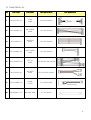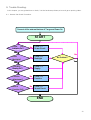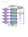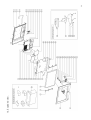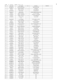
1
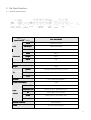
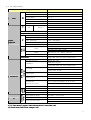
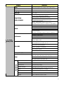
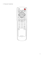
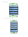
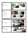
DLX32D1001
LCD TV
DLX-32D1SMSB
MAY, 2006
Contents
1. SAFETY PRECAUTION.
PRECAUTION.................................................................
................................................................................................
....................................................................
.................................... 4
1-1. IMPORTANT SAFETY FOR YOU AND TV SET. ............................................................................... 4
1-2. SAFETY PRECAUTIONS FOR SERVICE. ..................................................................................... 7
2. SET SPECIFICATIONS.
SPECIFICATIONS. ................................................................
................................................................................................
....................................................................
.................................... 8
2-1. GENERAL SPECIFICATIONS. ............................................................................................... 8
2-2. FULL SPECIFICATIONS. .................................................................................................... 9
2-3. RESOLUTION. ............................................................................................................. 12
2-3-1. PC Resolution. ................................................................................................... 12
2-3-2. DTV Resolution. .................................................................................................. 13
3. GENERAL PANEL SPECIFICATION.
SPECIFICATION.................................
CIFICATION. ................................................................
....................................................................................
.................................................... 13
4. REMOTE CONTROLLER.
CONTROLLER. ................................................................
................................................................................................
................................................................ 14
5. BLOCK DIAGRAM. ................................................................
................................................................................................
.......................................................................
....................................... 15
6. DESCRIPTION OF EACH
EACH BLOCK. ................................................................
......................................................................................
...................................................... 16
6-1. GRAPHIC SIGNAL PROCESS ACCORDING TO INPUT SOURCE. ........................................................... 16
6-2. VIDEO INPUT PROCESS. .................................................................................................. 16
6-3. VIDEO OUTPUT PROCESS. ............................................................................................... 17
6-4. AUDIO INPUT & OUTPUT PROCESS....................................................................................... 17
6-5. OPERATING PARTS & UPDATE PROCESS. ............................................................................... 18
7. CONNECTOR DESCRIPTION.
DESCRIPTION.................................
TION.................................................................
...........................................................................................
........................................................... 19
7-1. MAIN BOARD & ITS PIN ASSIGNMENT. ................................................................................... 19
7-2. TERMINAL PIN ASSIGNMENT OF MAIN BOARD AND SUB BOARD CONNECTOR. ........................................ 20
8. CABLE/WIRE LIST.................................
LIST.................................................................
................................................................................................
.......................................................................
....................................... 21
9. TROUBLE SHOOTING. ................................................................
................................................................................................
..................................................................
.................................. 22
9-1. GENERAL SET CHECK PROCEDURE...................................................................................... 22
9-2. POWER CHECK PROCEDURE. ............................................................................................ 23
9-3. PICTURE ON THE SCREEN CHECK PROCEDURE.......................................................................... 23
9-3. PICTURE ON THE SCREEN CHECK PROCEDURE.......................................................................... 24
9-4. S-VIDEO, AV1/2 CHECK PROCEDURE.................................................................................. 24
9-5. TV CHECK PROCEDURE. ................................................................................................. 25
9-6. PC, HDMI, COMPONENT CHECK PROCEDURE. ........................................................................ 25
9-7. KEY FUNCTION CHECK PROCEDURE ..................................................................................... 26
9-8. REMOTE CONTROLLER CHECK PROCEDURE. ............................................................................ 26
9-9. AUDIO CHECK PROCEDURE. ............................................................................................. 27
2
10. SET ASSEMBLY. ................................................................
................................................................................................
........................................................................
........................................ 27
10-1. ASSEMBLY OF FRONT PARTS. .......................................................................................... 27
10-2. ASSEMBLAGE OF IR ..................................................................................................... 28
10-3. ASSEMBLAGE OF PANEL SUB........................................................................................... 28
10-4. ASSEMBLAGE OF PANEL COVER. ....................................................................................... 29
10-5. ASSEMBLAGE OF FRONT & PANEL ASSEMBLY. ........................................................................ 29
10-6. ASSEMBLAGE OF BOARD................................................................................................ 30
10-7. ASSEMBLAGE OF PCB COVER.......................................................................................... 30
10-8. ASSEMBLY OF REAR COVER. ........................................................................................... 31
10-9. ASSEMBLAGE OF STAND. ............................................................................................... 31
10-10. SCREW SPECIFICATIONS. ............................................................................................. 32
11. FIRMWARE UPDATE ................................................................
................................................................................................
...................................................................
................................... 33
11-1. PREPARATION. .......................................................................................................... 33
11-2. SYSTEM CONFIGURATION. .............................................................................................. 33
11-3. CABLE CONNECTION. ................................................................................................... 34
11-4. UPDATE PROCEDURE. .................................................................................................. 34
12. FACTORY MODE.................................
MODE. ................................................................
................................................................................................
.......................................................................
....................................... 36
12-1. CALIBRATION. (NOT USED.)............................................................................................ 36
12-2. OPTION TABLE. ......................................................................................................... 36
12-3.COLOR CONTROL. ....................................................................................................... 36
12-4. DEVICE ADJUST. ........................................................................................................ 36
12-4-1. PW218. .......................................................................................................... 36
12-4-2. PW-Deinterlace................................................................................................. 36
12-4-3. PW-Enhancer. .................................................................................................. 36
12-4-4. ADC............................................................................................................... 36
12-4-5. TW9919. ......................................................................................................... 36
12-5. HEATRUN................................................................................................................ 36
12-6. VERSION. ................................................................................................................ 36
12-7. RESET. .................................................................................................................. 36
12-8. CH TEST. ............................................................................................................... 36
13. PARTS LIST. ................................................................
................................................................................................
............................................................................
............................................ 37
14. EXPLODED VIEW.
VIEW.. ................................................................
................................................................................................
.....................................................................
..................................... 39
3
1. Safety Precaution.
1-1. important safety for you and TV set.
Your product has been manufactured and tested with your safety in mind. However, improper use can result
in potential electrical shock or fire hazards. To avoid defeating the safeguards that have been built into your
new product, please read and observe the following safety points when installing and using your new product,
and save them for future reference.
Observing the simple precautions discussed in this booklet can help you get many years of enjoyment and
safe operation that are built into your new product.
Read Instructions.
Instructions.
All the safety and operating instructions should be read before the product is operated.
Follow Instructions.
Instructions.
All operating and use instructions should be followed.
Retain Instructions.
Instructions.
The safety and operating instructions should be retained for future reference.
Heed Warnings.
Warnings.
All warnings on the product and in the operating instructions should be adhered to.
Water and Moisture.
Moisture.
Do not use this product near water, for example, near a bath tub, wash bowl, kitchen sink, or laundry tub, in
a wet basement, or near a swimming pool. The apparatus shall not be exposed to dripping or splashing and
that no objects filled with liquids, such as vases, shall be placed on the apparatus.
Accessories, Carts, and Stands.
Stands.
Do not place this product on a slippery or tilted surface, or on an unstable cart, stand, tripod, bracket, or
table. The product may slide or fall, causing serious injury to a child or adult, and serious damage to the
product. Use only with a cart, stand, tripod, bracket, or table recommended by the manufacturer, or sold
with the product. Any mounting of the product should follow the manufacturer's instructions, and should use
a mounting accessory recommended by the manufacturer.
Transporting Product.
Product.
A product and cart combination should be moved with care.
Quick stops, excessive force, and uneven surfaces may cause the product
and cart combination to overturn.
4
Attachments.
Attachments.
Do not use attachments not recommended by the product manufacturer as they may cause hazards.
Ventilation.
Ventilation.
Slots and openings in the cabinet are provided for ventilation and to ensure reliable operation of the product
and to protect it from overheating, and these openings must not be blocked or covered. The openings should
never be blocked by placing the product on a bed, sofa, rug, or other similar surface. This product should
not be placed in a built-in installation such as a bookcase or rack unless proper ventilation is provided or the
manufacturer's instructions have been adhered to. Separate the product from the wall, and keep a distance
of more than 10cm.
Power Sources.
Sources.
This product should be operated only from the type of power source indicated on the marking label. If you
are not sure of the type of power supply to your home, consult your product dealer or local power company.
For products intended to operate from battery power, or other sources, refer to the operating instructions.
Outdoor Antenna Grounding.
Grounding.
If an outside antenna or cable system is connected to the product, be sure the antenna or cable system is
grounded so as to provide some protection against voltage surges and built-up static charges.
Lightning.
Lightning.
For added protection for this product (receiver) during a lightning storm, or when it is left unattended and
unused for long periods of time, unplug it from the wall outlet and disconnect the antenna or cable system.
This will prevent damage to the product due to lightning and power-line surges.
Power Lines.
Lines.
An outside antenna system should not be located in the vicinity of overhead power lines or other electric light
or power circuits, or where it can fall into such power lines or circuits. When installing an outside antenna
system, extreme care should be taken to keep from touching such power lines or circuits as contact with
them might be fatal.
5
Overloading.
Overloading.
Do not overload wall outlets and extension cords as this can result in a risk of fire or electric shock.
Heat.
Heat.
The product should be situated away from heat sources such as radiators, heat registers, stoves, or other
products (including amplifiers) that produce heat.
Cleaning
Cleaning.
leaning.
Unplug this product from the wall outlet before cleaning. Do not use liquid cleaners or aerosol cleaners. Use
a dry cloth for cleaning.
Servicing.
Servicing.
Do not attempt to service this product yourself as opening or removing covers may expose you to dangerous
voltage or other hazards. Refer all servicing to qualified service personnel.
Damage Requiring Service.
Service.
Unplug this product from the wall outlet and refer servicing to qualified service personnel under the following
conditions:
- When the power-supply cord or plug is damaged.
- If liquid has been spilled, or objects have fallen into the product.
- If the product has been exposed to rain or water.
- If the product does not operate normally by following the operating instructions. Adjust only those
controls that are covered by the operating instructions as an improper adjustment of other controls may
result in damage and will often require extensive work by a qualified technician to restore the product to
its normal operation.
- If the product has been dropped or the cabinet has been damaged in any way.
- When the product exhibits a distinct change in performance.
Whenever you connect all external A/V equipment to your television, ensure that all equipments are
switched off. Also refer to the user manual supplied with your A/V equipment for detail connection
instructions and associated safety precaution.
The mains plug is used as the disconnect device. The disconnect device shall remain readily operable.
* The socket-outlet shall be installed near the apparatus and shall be easily accessible.
6
1-2. Safety precautions for service.
When moving or laying down a TV set, at least two people must be working. Avoid any impact towards the
TV set.
Do not leave the broken TV set on for a long time. To prevent any further damages, after check the
broken set s condition, make sure to turn the power (AC) off.
When opening the back cover, turn off the power (AC) to prevent electric shock. When a TV set is on,
high voltage and high current exist inside the set.
When loosening screws, check the connecting position and type of the screw. Sort out the screws and
store them separately. Because screws holding PCB are working as electric circuit grounding, make sure
to check if any screw is missing when assembling.
A TV set contains different kind of connector cables. When connected or disconnected connector cables,
check the direction and position of the cable beforehand.
When disconnecting connectors, unplug the connectors slowly with care.
Connectors are designed so that if the number of pins or the direction does not match, connectors will not
fit. When having problem in plugging the connectors, make sure to check their kind, position, and
direction.
7
2. Set Specifications.
2-1. General Specifications.
Model
Specifications
LCD
Panel
Resolution
Screen Size
Width
Dimension
Height
Depth
Aspect ratio
1366 X 768 (WXGA)
697.68(H) x 392.26(V)
985.5
654.5
106
25kg
System
TV
Tuning
Cable
Speaker
3System (NTSC-M, PAL-M, PAL-N)
FS
125 Channels
Up to 10Wx2 (6
Power Consumption
Component 1/2
PC
Source
HDMI
Antenna
Remote Controller
Speaker)
175W
Video 1/2
Power
32inches TFT LCD
16:9
Weight
Input
DLXDLX-32D1SMSB
RCA 2 / Stereo L/R
RCA (Y Pb Pr) 2, RCA Stereo (L/R)
Analog RGB (15 Pin D-Sub)
HDMI (Type A), RCA Stereo (L/R)
75ohm Coaxial Cable/F-Connector
DDR-2020000
AC 110~240V, 50/60Hz
8
2-2. Full Specifications.
Category
Type
LCD Panel
Aspect Ratio
16 : 9
Supported Pixel Rate
1366 x 768
Panel
LCD
Vendor
Samsung
Refresh Rate
TV
Interface
US
Analog
CVBS / SS-Video
H. Frequency Range
PC
V. Frequency Range
Supported
MAX. Resolution
MAX. Pixel Rate
DTV mode Support
(DVI)
HDMI
VIDEO
AUDIO
DVI Sound In
Data Protection
RS-232 (for A/S)
MAIN
(Universal)
BOARD
HDMI(DVI)
Connections
SUB
BOARD
(NTSC)
PAL-M / PAL-N
480i , 480p , 720p, 1080i
20 ~ 72 kHz
55 ~ 90 Hz
1360 x 768 @60Hz
*1)
110 MHz
480p, 720p, 1080i
RGB (8 bit per Channel)
Y/Cb/Cr (Uncompressed)
Max pixel input: 1920 x 1080i
@2 Channels: 32 ~ 48kHz / Channel
HDCP v.1.1
RCA Audio Stereo Input
(Applicable when using DVI to HDMI Cable)
Stereo Jack Type
HDMI Jack (Type A)
HDMI Audio (RCA Stereo L/R Input for DVI)
(Applicable when using DVI to HDMI Cable)
Stereo Audio-In Jack
3 RCA (Y Pb Pr)
Component1
RCA Stereo (L/R)
Component 2
*2)
(Internal Connector)
SU
SUB
B BOARD
(NTSC)
LVDS
NTSC-M
PAL-M
PAL-N
Analog RGB (15 Pin D-Sub)
PC (RGB)
Speaker Out
TV
50Hz, 60Hz
NTSC-3.58 /
Component 1/2
Signals
Dimension
3 RCA (Y Pb Pr)
RCA Stereo (L/R)
Up to 15Wx2 (4
Up to 10Wx2 (8
Speaker, 1KHz, d=10%)
Speaker, 1KHz, d=10%)
AUDIO Line-Out
RCA Stereo L/R Out
AV 2
Video &
AV 1
S-Video or Video, and RCA Stereo L/R
RCA Stereo L/R
TV Antenna
Antenna In (75ohm Coaxial/(F-connector)
Video System (NTSC)
NTSC-M, PAL-M, PAL-N
RF Frequency Range
Sound System (NTSC)
55.25MHz ~ 801.25 MHz
MTS (Mono, Stereo, SAP)
BTSC
*1) PC Input doesn t support 1360 x768 resolution in some VGA card.
*2) Normal Au
Audio AMP Power Voltage
Voltage is 24V.
9
Category
Color
Type
Language
OSD Size
Image Setting
(Video & Graphic)
Sound
PC Function
On Screen
Dimension
8bit Color (256 Color Palette from 16bit Color)
Graphical & Text User Interface
English, French, Spanish, Portuguese
703 X 422
Contrast / Brightness / Sharpness / Color / Tint
5 Color Tone Temperature Modes
(Normal/Warm1/Warm2/Cool1/Cool2)
5 Picture Modes
(Standard/dynamic/Mild/Movie/Custom)
5 Aspect Ratio Modes
(Wide / Panorama / Zoom / 14:9 / 4:3)
(Up/down Scroll function in Zoom & 14:9 Mode)
Volume / Balance
5 band equalizer
Mono / Stereo / MTS
Auto Volume Level
5 Sound Modes
(Custom / Standard / Music / Movie / Speech)
Auto Adjustment
Frequency Adjustment
Phase Adjustment
Position Adjustment
Aspect ratio Change
(Wide / Real / 4:3)
Graphic vs. Video
( Not support G vs. G & V vs. V)
Display (OSD)
*3)
PIP & PBP
Sub Picture Source Select
Sub Picture Size
(Small / Double1 / Double2)
Sub Picture Position
V-chip / CC (US)
(US)
Timer
Supported
Sleep
(Off / 30 / 60 / 90 /120 / 150 / 180 min)
Wake up ON & Power OFF Reservation
Blue Screen Function
Last Power State Save
Miscellaneous
Picture Swap
On Time Channel & Volume Set
Blue Back Screen
Remember the last state before power-off
Picture still
Pause moving image
DNR
Digital Noise Reduction of Image
HDMI & HDCP
High Digital Multimedia Interface
High-Bandwidth Digital Content Protection
Pixel Shift
Pixel Burning Protection
Wiper
Clear & Refresh whole screen.
Key Lock
Disable all the buttons on TV set.
10
*3)
*3) PIP & POP Support Table.
Table.
SUB
TV
AV1
S-Video
AV2
DTV
Component
1
Component
2
PC
HDMI
TV
X
X
X
X
X
O
O
O
O
AV1
X
X
X
X
O
O
O
O
O
S- Video
X
X
X
X
O
O
O
O
O
AV2
X
X
X
X
O
O
O
O
O
DTV
X
O
O
O
X
X
X
X
X
Component
1
O
O
O
O
X
X
X
X
X
Component
2
O
O
O
O
X
X
X
X
X
PC
O
O
O
O
X
X
X
X
X
HDMI
O
O
O
O
X
X
X
X
X
MAIN
*Video =
*Graphic
TV, AV Input
= DTV, Component, Analog RGB, HDMI.
11
2-3. Resolution.
2-3-1. PC Resolution.
Section
Resolution
640x400
640x350
H Frequency
Frequency (KHz)
V Frequency (Hz)
Pixel Frequency (MHz)
31.469
70.087
25.175
37.861
37.861
31.469
640x480
43.269
85.008
36.0
37.500
31.469
37.927
1280 X 960
46.875
85.039
56.25
70.020
75.0
53.674
85.061
43.163
62.5
100
36.0
45.5
49.5
56.25
60.065
48.780
60.001
64.11
56.476
70.069
60.030
60.241
60.004
75.029
74.927
84.997
66
75.0
78.75
80
94.5
100.187
60
81.6
75.0
104.993
72.713
76.047
105.561
60.000
60.0
102.104
60.02
108.0
100.795
62.932
69.924
61.846
66.0
53.700
67.500
47.700
60.0
63.337
59.978
64.754
60.060
74.664
70.032
74.405
78.125
91.146
91.375
110
94.787
80.136
108.18
125
72.005
135
85.024
85.0
60
Out of range
96.6
69.995
75.025
Out of range
65.0
90.0
81.845
Out of range
35.5
90.0
79.976
1360 X 768
28.322
100
50.0
63.981
1280 X1024
70.087
72.188
72.810
1280 X 768
37.889
48.077
68.677
1152 X 900
90.0
40.0
48.363
1152 X 864
31.5
60.317
56.880
1152 X 864
75.0
37.879
43.764
1024 X 768
25.175
29.765
35.156
PC
59.94
31.5
72.809
50.900
800x600
85.08
31.5
37.861
45.540
720 X 400
85.08
Comment
135
Out of range
Out of range
Out of range
Out of range
Out of range
Out of range
Out of range
Only nVidia
* Shade Box is Not Support or requires compatibility Test.
Test.
12
2-3-2. DTV Resolution.
Section
Resolution
720 X 480
H Frequency
(KHz)
V Frequency
(Hz)
Pixel Frequency
(MHz)
31.5
60
27.027
720 X 480
720 X 576
DTV
31.469
31.250
59.94
50.0
25.175
26.566
1280 X 720
44.964
59.94
74.176
1920x1080
33.750
60.0
74.25
1920x1080
33.176
59.94
74.176
1920x1080
31.25
49.96
74.25
1280 X 720
1920x1080
45
28.125
Comment
60
74.25
50.0
74.25
*DVI doesn t support PC resolutions,
resolutions, it only support
support DTV resolutions!
3. General Panel Specification.
Screen Size(mm)
Pixel Pitch(mm)
Min
697.68(H) x 392.256(V)
Max
0.51075(H) x 0.51075(W)
Luminance/Brightness
450cd/m
500cd/m
Viewing Angle
170(Degrees)
178(Degrees)
Contrast Ratio
700 : 1
1200 : 1
Because Standard
Standard of reject is decided according to outgoing inspection criteria and approval of panel maker,
Defect panel should be referred to panel maker or its documents.
13
4. Remote Controller.
14
5. Block Diagram.
15
6. Description of each Block.
6-1. Graphic Signal Process according to Input Source.
Graphic signal is processed from each source input to ADC/TMDS as a bellows,
1) HDMI(DVI) Input Signal : Pin 108, 109, 111, 112, 114,115, 117, 118, 124,125.
2) D-SUB Input Signal : Pin 2, 3, 6, 7, 8, 9, 10, 11, 12.
3) Component 1 Input Signal : Pin 15, 16, 17, 18, 19, 20, 21.
4) Component 2 Input signal : Pin 1,3,5.
Component Output : From Pin 15, 19, 21 of MUX to Pin 22, 23, 24, 25, 26, 27, 28 of ADC.
And each graphic input signal is transmitted to scaler IC of 24-bit RGB signal, HDMI audio signal is
transmitted from ADC to audio processor.
6-2. Video Input Process.
Processing From video input port to video decoder as a bellows,
1) AV1 Input Signal : Decoder Pin 58 from CVBS signal.
2) AV2 : Decoder Pin 57 from AV2 CVBS signal.
3) TUNER : Decoder Pin 59 CVBS signal of Tuner.
Video signal from CVBS and Y, C signal of decoder is transmitted to scaler with 8Bit CCIR656 format.
16
6-3. Video Output Process.
Signal from ADC and video decoder is transmitted to Scaler PW218, actually displaying on the screen,
output signal through LVDS interface is displayed on LCD or PDP panel.
6-4. Audio Input & Output process.
Audio signal from Audio Processor is processed from audio AMP to speaker as a bellows,
1)
2)
3)
4)
5)
6)
7)
8)
Tuner Input : Pin 67 of audio processor from tuner SIF signal.
PC Input : Pin 53, 54 of audio processor from PC audio signal.
DVI Input : Pin 56, 57 of audio processor from DVI audio signal.
Component 1 : Pin 50, 51 of audio processor from component 1 signal.
Component 2 : Pin 47, 48 of audio processor from component 2 signal.
AV 1/2 : Pin 59,60 of audio processor through MUX audio signal from AV 1/2.
2
HDMI : Pin 19,20,22 of audio processor from HDMI I S(Inter-IC Sound) of ADC pin 96, 97, 98.
Audio Line Out : Pin 33, 34 of audio processor.
17
6-5. Operating parts & Update Process.
SCALER
(PW218)
Control B/D
LED
KEY
RCU
RECEIVER
M
U
X
UART
for A/S
STEREO JACK
UART
for TV
Internal CON.
1) Key : Signal of Key board is transmitted directly to pin port B0~B6 of scaler.
2) IR : Signal of IR board is transmitted directly to IRRCVR0 of scaler.
3) LED : LED signal is outputted from IN1B4, IN1B5 to control pin 1, 2 of scaler.
4) Update : UART Port signal of Main board from serial port of PC is transmitted to RXD, TXD of scaler.
18
1
3
7-1. Main Board & its Pin Assignment.
7. Connector Description.
2
4
Con18
12V
12V
NC
GND
5V
5V
Stby5V
GND
BRI-ADJ
GND
BLU On
SMPS ON
Pin No
1
2
3
4
5
6
7
8
9
10
11
12
13
14
Con31
V_amp
V_amp
GND
GND
2 - Con31
Audio Power
4
Con25
LED_G
LED_R
GND
Key_Ch+
Key_ChKey_VolKey_Vol+
Key_power
GND
Key_Menu
Key_Input
IR IN
3V3
GND
3 - Con25
IR & Key
14
Con15
LeftLeft+
Left+_SW
RightRight+
Right+_SW
4 - Con15
Speaker
6
NC = Not Connection
V_amp (Power for Audio AMP.) = 12 ~ 30V,
(Normally 24V (at least) for Enough Audio Power)
Not used connector : CON36, CON37, CON32, CON35.
CON17 is used as a LVDS connector.
1 - Con18
Power
12
Terminal PIN Assignment of Main Board.
Loc.
Loc. / No
Name
Pin Number
Table No. 1
19
1
7-2. Terminal PIN Assignment of Main Board and Sub Board Connector.
HS_CVBS_OUT
15
14
13
S-Video_DET
GND
AV1_CVBS
AV1_DET
12
11
FS_ID
HS_ID
FS_CVBS
HS_CVBS
GND
GND
FS_FB
SUB B/D(or SUB Module)
Connection
CON 23
30
29
28
27
26
25
24
23
22
21
20
19
TV_L_out
TV_R_out
9V_MUX
GND
GND
Tuner_SIF
20
Tuner_CVBS
GND
GND
5V_ Standby
S-Video_C
AV2_DET
GND
AV2_CVBS
18
S-Video_Y
17
16
Pin Name
Pin No.
SH1605-230 (female)
60pin ( pin1~40 is for Analog TV)
10
9
8
7
6
5
4
3
FS_R
FS_B
FS_G
2
1
Pin Name
Pin No.
Type
No. of pin
Function
Location No.
8. Cable/Wire List.
No
Part Code
Part Name
Part Specification
1
DD-L32LVD-40
LVDS
Cable
30P*30P*260mm
2
DD-L32ADP-40
AD POWER
Cable
12P*15P*300mm
3
DD-L32INV-20
INVERTER
Cable
14P*15P*400mm
4
DD-L32AMP-40
AMP POWER
Cable
4P*15P*250mm
5
DD-L32KEYIR-40
KEY-IR
Cable
14P*8P*6P*400*500mm
6
DD-L32SPK-40
SPEAKER
Cable
6P*LUG(A,B)*550mm
7
DD-L32MPN-30
NOISE
FILTER
2P*350mm+GND
8
DDL32GND--40
GROUND WIRE
1P*1P*200mm
Part Appearance
Appearance
21
9. Trouble Shooting.
In this chapter, you are guided how to check, find the hardware problem points and get a repairing ideas.
9-1. General Set Check Procedure.
Connect
Connect all
all the
the external
external devices
devices of
of Tango
Tango and
and Power
Power On
On
START
START
Power
Power LED
LED
Indicator
On?
Indicator On?
No
Check
Check 1.1.
1.1.
Power
Circuit
Power Circuit
Yes
No
Panel
Panel
Backlight?
Backlight?
No
Check
Check 1.2.
1.2.
Backlight
Backlight
Yes
Yes
TV/VIDEO
TV/VIDEO
Display
Display OK?
OK?
No
No Problem?
Problem?
No
Check
Check 1.3.
1.3.
Display
Display
No
Check
Check 1.4.
1.4.
Function
Function
No
Check
Check 1.5.
1.5.
Sound
Circuit
Sound Circuit
Yes
Function
Function
Adjustment?
Adjustment?
Yes
Sound
Sound
Function
Function OK?
OK?
END
END
22
9-2. Power Check Procedure.
START
START
Replace
Replace SMPS
SMPS
Check
Check for
for AC
AC
Cord
or
SMPS
Cord or SMPS
No
Re-connect AC-Cord
Re
AC
Re-connect
AC-Cord
or
or SMPS
SMPS
Yes
YES
Power
Power circuit
circuit
normal?
normal?
No
Check
Check regulators
regulators
(U61,
U63,
(U61, U63, U64,
U64, U74)
U74)
Yes
Check
Check 14.318
14.318
(Y3)
oscillator
(Y3) oscillator
No
Check
Check Crystal
Crystal
PW218
PW218
No
Check
Check Reset
Reset signal
signal
(R307)
(R307)
No
Check
Check
peripheral
peripheral circuit
circuit
Check
Check con26,
con26, 27,
27, 28
28
No
No
Problem?
Problem?
NO
or
or
Yes
Reset
Reset PW218
PW218
Reset
switch
Reset switch
Yes
I2CBus
I2CBus signal
signal
normal?
normal?
END
END
23
9-3. Picture on the screen Check Procedure.
START
START
Check
Check LVDS
LVDS cable
cable &
& Main
Main
board
-- ReRe
board connection
connection
Reconnect
connect LVDS,
LVDS, Mainboard
Mainboard
cable
cable
Check
Check Power
Power line(u62,
line(u62, FB48)
FB48)
END
END
9-4. S-Video, AV1/2 Check Procedure.
START
START
Check
Check peripheral
peripheral devices
devices
(VCR,
DVD
(VCR, DVD Player..
Player.. etc)
etc)
connection
connection
Check
AV
Check
AV
Decoder(U49)
Decoder(U49)
Video
Video
Check
Check Video
Video clock
clock
Check
Check Reset
Reset signal(Q2)
signal(Q2)
Check
Check I2C
I2C Bus
Bus Line
Line
(r434,
r435)
(r434, r435)
END
END
24
9-5. TV Check Procedure.
START
START
Check
Check
Sub board connection
TV board connection
Check
Check TV
TV Tuner
Tuner input
input
(75
RF
In)
Ω
(75 Ω RF In)
Check
Power
inlet signal
Check TV
Tuner
power
(U13, U14 / 5V)
Tuner
Checkpower
Tunersignal
power(U46/U47) is normal?
(U15/U32)
Check Tuner I2C bus
(R115, R117)
END
9-6. PC, HDMI, Component Check Procedure.
START
START
Check
Graphic
A/D
Check
Graphic
A/D
converter
converter power(3.3,
power(3.3, 2.5V)
2.5V)
Check
Check A/D
A/D converter
converter main
main
clock(Y4)
clock(Y4)
Check
Check Video
Video Decord
Decord Reset
Reset
Line(U44
Line(U44 –– pin35)
pin35)
Check
Check I2C
I2C bus(R409,
bus(R409, R410)
R410)
## Optional
Optional (Only
(Only HDMI/DVI)
HDMI/DVI)
Check
Check DDC
DDC data
data // HDCP
HDCP ––
Check
Check windows
windows Regisy
Regisy //
check
check HDCP
HDCP Title
Title
END
END
25
9-7. Key Function Check Procedure.
START
START
Check
Check Key
Key board
board connection
connection
Check
Check key
key switch
switch
Replace
Replace Key
Key board
board
END
END
9-8. Remote Controller Check Procedure.
START
START
Check
Check Remote
Remote Controller
Controller
and
and Battery
Battery
Check
Check IR
IR Board
Board Connection
Connection
Check
Check Power
Power on
on Signal
Signal
Replace
Replace IR
IR Board
Board
END
END
26
9-9. Audio Check Procedure.
START
START
Check
Check the
the connect
connect for
for SMPS
SMPS
cable
&
Speaker
cable
cable & Speaker cable
Cheak
Cheak Audio
Audio AMP(24V
AMP(24V //
Con31)
Con31)
Check
Check Audio
Audio Power
Power
regulater(U66,
regulater(U66, U68)
U68)
--
Check
-21pin)
line(U51
Check Reset
Reset line(U51line(U51-21pin)
Check
Check I2C
I2C bus(R488/R489)
bus(R488/R489)
END
END
10. Set Assembly.
10-1. Assembly of Front Parts.
Step 1
Put down the front
Step 2
Assemble Speaker elbow
Use the Screw No.1 (4EA)
Step 3
Assemble L/R Speaker Unit
Use the Screw No.2 (8EA)
27
10-2. Assemblage of IR
Step 1
Assemble Window IR
Step 2
Assemble Knob Stand-by
Use the Screw No. 2 (4EA)
Step 3
Assemble Window Plate
Step 4
Assemble Key IR
Use the Screw No. 2 (2EA)
10-3. Assemblage of Panel Sub.
Step 1
Open the Box & Put down the Panel
Step 2
Assemble Panel Bracket Samsung
Use the Screw No. 3 (6EA)
28
10-4. Assemblage of Panel Cover.
Step 1
Assemble Stand Support
Use the Screw No.2 (2EA)
Step 2
Assemble Panel Cover Ass y
Use the Screw No.4 (4EA)
10-5. Assemblage of Front & Panel Assembly.
Step
Step 1
Assemble Front & Panel Ass y
Use the Screw No.2
15ea- Top 4EA, Bottom 5EA,
L/R 6EA )
29
10-6. Assemblage of Board.
Step 1
Assemble 218 Board
Use the Screw No. 5 (12EA)
Step 2
Assemble Noise filter
-Assemble Earth bolt
Use the Screw No. 6(1EA)
-Assemble Noise filter
Use the Screw No. 7(2EA)
-Assemble Cable
(Bottom Position Green)
10-7. Assemblage of PCB Cover.
Step 1
Assemble PCB Cover
Use the Screw No.2 (12EA),
No.3 (2EA)
Step 2
Assemble PCB Cover
Use the Screw No.4 (1EA) ,
No.8 (7EA) ,
No.9 (2EA)
30
10-8. Assembly of Rear Cover.
Step 1
Assemble Knob Control
Use the Screw No.7 (6EA)
Step 2
Assemble Rear Cover
Use the Screw No. 10 (13EA)
Use the Screw No. 1 (1EA)
10-9. Assemblage of Stand.
Step 1
Assemble Stand Cover
Step 2
Assemble Stand Base
Use the Screw No.11 (4EA)
No.2 (4EA)
Step 3
Assemble Rubber
Step 4
Assemble Stand Ass y
Use the Screw No.12 (6EA)
31
10-10. Screw Specifications.
NO.
IMAGE
SORT
NAME / SPEC
1
Taptite + Washer + Panhead
TWP 3*6 Black
2
Taptite + Panhead
T/T-BP+4*8
3
Machine Screw + Panhead
P+4*6
4
Machine Screw + Washer+
Panhead
WP+4*8 Black
5
Machine Screw + Plain Washer
+ Spring Washer
SW/PW BP+3*8
6
Machine Screw + Panhead +
External Teeth Washer
T/T CT BB+4*10
7
Machine Screw + Panhead
BP+3*10
8
Taptite + Bindhead
T/T-BB+3*8
9
Hexa Nut
HEXA NUT
10
Taptite + Bindhead
T/S 2B+4*14 Black
11
Machine Screw
OVEL + M4*10
12
Machine Screw + Trusshead
T+4*16 Black
32
11. Firmware Update
11-1. Preparation.
. LCD/PDP TV Set.
. Update Cable (RS-232C to Stereo Phone Cable).
. IBM Compatible PC.
11-2. System Configuration.
. PC Configuration
Because the update requires RS-232C port of PC, all the configuration of Serial Port
(COM1/COM2) should be done before proceed.
Be sure Communication Port is
installed properly as seen on the
figure.
If Communication (Serial) Port is not installed, check your CMOS (Computer System Menu) and activate Serial
Port in it.
33
11-3. Cable Connection.
Connect Serial Port of PC to Update Port of TV through RS-232C to Phone Cable.
(Communication Port of PC)
(Update Port of LCD/PDP Set)
11-4. Update Procedure.
. Main Power off (Unplug the power cord).
. Unzip Firmware File attached together and execute FlashExpress_nologo.exe in the folder.
(Update Application Window)
. Set Serial Port (COM1 or COM2) properly and the Update speed to 115200
. Be sure WARE3.INF is shown as the above figure and click Flash.
. Main Power on (Plug the power cord)
34
(Firmware Update in Progress)
. F/W Update is automatically started once power is on. You can see the progress bar as the above
figure.
Be sure to check the COM1/COM2 is selected right if it does not start.
. Please wait till all the process is done. (It will take around 30 seconds to be done.)
(Firmware Update is completed.)
. After all the update process is done, do Factory Reset.
To enter Factory Mode, push the buttons as following within 2 seconds.)
(1
MUTE
Enter
MUTE)
. In Factory Menu, Select 7. Reset and Push Enter.
35
12. Factory Mode.
12-1. Calibration. (Not Used.)
12-2. Option Table.
. Sound Mute Set
. Default Language Set.
12-3.Color Control.
. R, G, B color offset and gain set.
12-4. Device Adjust.
12-4-1. PW218.
. Input Mode set to work Pixel Shift.
. Pixel Number Set.
. Pixel Shift Interval Set.
. Wiper Interval Set.
. Wiper Speed Set.
12-4-2. PW-Deinterlace.
. Set Internal Register of PW218 Scaler.
12-4-3. PW-Enhancer.
. Set Internal Register of PW218 Scaler.
12-4-4. ADC.
. Set offset and gain of MST3388 ADC.
12-4-5. TW9919.
. Set Internal Register of TW9919 Video Decoder.
12-5. HeatRun.
. Output engine of Scaler and Test pattern display.
12-6. Version.
. Check Version, released date, etc. as a bellows,
Model
Tango - Tri _ D2
Version
M : MP (Mass Product)
4 & 5 digit
05 : Month
8 ~10 digit
V01 : Update Number
2
nd
th
& 3 digit
rd
th
6 & 7 digit
th
th
th
th
Release Day:
Release Time:
Panel Used Time:
12-7. Reset.
M 06 05 19 V01
1 digit
st
Panel Name:
06 : Year
19 : Day
Date debugged F/W
Time debugged F/W
Time used Panel
Panel Name of Set
. E PROM Data Clear
2
12-8. CH Test.
. Test Tuner using set frequency. (Euro Only)
36
13. Parts List.
No
1
2
3
4
Part Code
Part Name
DL320W2-L03J
Panel 32-SS
PAS-SIG6LIXA
IR&LED Board
K125B071----
LR-T11CLM---
SPEAKER UNIT/PAIR
4
330 ohm(1608)
2
Resistor Chip
MCR03-000J--
Resistor Chip
9
10
TR2SC2412KB-
12
14
11
13
15
16
17
18
SMW200--06P
Resistor Chip
Straight, 2mm, 6pin, SMW200-06
100 ohm (1608)
0 ohm(1608)
2SC2412K
NPN Transistor, SOT-23
CCA1HX7R560J
C Chip
56pF, 1608Size,
SKHV10910A--
TACT SWITCH
Push-On, Tact, DIP, 2pin
PCBLD32IR005
CCA1HX7R104J
PAS-SIGKEYA
WSMW200--08P
SKHV10910A--
PCB
C Chip
T=1.6*100*20/2L, IR&LED
100nF, 1608Size
1
1
1
1
SS 32" Panel, 218 AD & 3 System
22
PASS32PWR2
PCB
1
1
5
1
AV Board(3System)
SS 32" Panel, 218 AV & 3 System
1
DD-L32ADP-40
AD POWER
12P*15P*300MM
1
DDL32KEYIR40
KEY-IR
14P*8P*6P*400MM*500mm
1
24
DD-L32AMP-40
26
DD-L32SPK-40
28
DD-L32INV-20
27
1
T=1.6*74*33.4/2L, Button
AD Board(3System)
25
1
5
Straight, 2mm, 8pin, SMW200-08
PASS32USD3SD
23
3
Push-On, Tact, DIP, 2pin
SMW200--08P
20
PASS32USD3SV
8
TACT SWITCH
100nF, Axial Type
21
1
Key Board Ass'y, PCB Silk : PCBLD32BU002
Capacitor
PCBLD32BU002
1
Key Board
CCAX-1H104K-
19
1
LED BLUE/ RED
MCR03-101J-MCR03-331J--
1
LEDRB1R3204C
7
8
IR&LED Board Ass'y, PCB Silk : PCBLD32IR005
1
IR Receiver with Amp, 38KHz,SI5315-H/SI5314-H
WSMW200--06P
LEDRB1R3204C
K125B071,(6 *10W)*2
Qty.
LR-T11CLM
5
6
LTA320W2
Part Specification
DD-L32LVD-40
POWERVALLY 32" POWER
POWER
SPEAKER
LVDS
INVERTER
LVDS 5V/3.5A, LD-3200T PowerValley
4P*15P*250MM
1
1
6P*LUG(A,B)*550MM
1
14P*15P*400MM
1
30P*30P*260MM
1
29
DDL32GND--40
Ground wire
Ring Washer *200mm
31
RE-BLSIDWEA1
REMOCON-LCD/PDP 3SYS
DEAWOO/BLACK
1
Power Cord-Italy
250V 10A 1.8M
1
Battery
AAA
COVER REAR-326-DW
MOLD/ABS/BLACK
30
DD-L32MPN-30
POWER NOISE FILTER
32
DPACC0000-12
POWER CORD-USA
34
MA-BDWL--3S1
MANUAL LCD/218
36
DL3260M150A2
COVER FRONT-326-DW
DL3280M181BA
KNOB CONTROL-3280-DW
33
35
DPACC0000-13
DPC9700000A
37
DL3280M160BA
39
DL3280M190CA
41
DL3280M210A
38
40
42
43
DAEWOO/3SYS/ENGLISH
MOLD/ABS/2TONE
MOLD/ABS/BLACK
KNOB STANBY-3280
MOLD/ABS/Cr
WINDOW PLATE-3280
MOLD/ACRYL/1.2T
WINDOW IR-3280
DL3280P304A
PANEL COVER-3280-NT
PRESS/EGI/1.2T/218NT/3S
STAND SUPPORT-3280
PRESS/EGI/2.0T
DL3280P314A
DL3280P350B
46
DP4260M113A
48
DL3280S700A
47
125V 10A 1.8M
DL3280M200A
44
45
NOISE FILTER*2P+GND(ID-1022-S)
PCB COVER-3280-NT
MOLD/PA
PRESS/EGI/1.6T/218NT/3S
DL3280P390A
BK'T PANEL-SS-3280
PRESS/EGI/1.0T
DL3280S690A
GASKET TUNER
D#/L50*15W*18T
SPEAKER ELBO-4260
GASKET D-SUB
MOLD/ABS/2.0T/SILVER
W36*H18*2.0T
1
1
1
1
2
1
1
1
1
1
1
1
1
1
2
2
1
1
37
No
Part Code
Part Name
Part Specification
49
DL3280S680A
GASKET LVDS
AL/W110*H80
51
DL3260S650A
FRONT CUSHION-S
SPONGE FORM/5W*L403*1.0T/35KG
50
52
53
DL3260S640A
DL3260S700A
DL3260S660A
FRONT CUSHION-L
PCB COVER CUSHION
2
SPONGE FORM/5W*L480*1.0T/35KG
1
SPONGE FORM/5W*L85*1.0T/35KG
1
SPONGE FORM/8W*L100*5.0T/35KG
DL3260S670A
REAR INSULATION SHEET-L
non-woven fabric/5W*L860*0.5T
57
DP4200S654A
INSULATION SHEET-S
non-woven fabric/0.8T/15W*45L
59
DARC-4
DP4260S690A
56
DL3260S680A
55
58
60
CUSHION NOISE
REAR INSULATION SHEET-S
DACT100-2.5
TIE CABLE-100
DL326-DW-01
BOX PACKING-3260
non-woven fabric/5W*L480*0.5T
1
63
P-MB-30-0150
MARK BRAND/32"~37"
METAL/DAEWOO DE
65
999000001200
ACCESSORY BAG
67
DL3280S642A
PAD TOP/R-3280
66
68
69
DL3280S672A
DL3280S641A
DL3280S643A
DL3280S644A
70
DL3280M170A2
72
DL3280P330A
71
DL3280P320A
73
DL3280TR673A
75
SM003
74
76
77
78
79
80
81
82
SM002
SM004
SM006
SM013
POLY-BAG-3280
DAEWOO/LATIN AMERICA
LDPE 0.5T*1010*960
VINYL/0.3T*245*360
PAD TOP/L-3280
EPS
PAD BOTTOM/L-3280
EPS
PAD BOTTOM/L-3280
COVER STAND-326-DW
STAND BASE-3280
EPS
MOLD/ABS/SILVER
PRESS/CR/3.0T
PRESS/EGI/4.0T
SCREW MECHINE 4
WP+4*8
SCREW MECHINE 4
SCREW MECHINE 3
SCREW MECHINE 4
SCREW MECHINE 3
34*
T/T-CT+4*10
P+3*10
P+4*6
ST104
SCREW TAPTITE 4
T/T-BP+4*8
87
SM011
SCREW MECHINE 4
4
1
2
6
4
85
SCREW MECHINE 4
4
FLAT-C+4*10 Zn
M4-NUT/3T
SM27
1
13
NUT 4
86
1
T/S-2B+4*14
SN301
SCREW TAPTITE 4
1
47
T/T-BP+3*8
ST105
12*2T
1
T/T-BP+4*8
SCREW TAPTITE 3
83
84
1
12
ST101
SCREW TAPTITE 4
1
TWP+3*8
TWP+3*6
ST104
1
12
SCREW TAPTITE 3
SCREW TAPTITE 3
1
S/W P/W P+3*8
ST107
ST108
1
1
EPS
EVA75%/
1
1
STAND BK'T-A-3280
RUBBER STAND-3280
2
6
2
DAEWOO/LATIN AMERICA
64
2
DAEWOO/MEXICO
BACK LABEL-3260
LABEL AV-32"~37"LCD
2
1
ID 5.1, L=75
LBL3260DAE-01
DL3260B614C
2
NY/100mm
COIL RETAINER/42-61
61
62
1
SPONGE FORM/5W*L719*1.0T/35KG
PANEL CUSHION
54
Qty.
T+4*12
1
8
4
4
6
38
14. Exploded view.
39
40