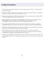
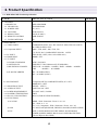
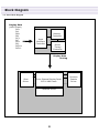
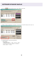
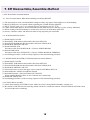
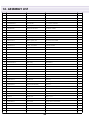
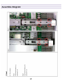
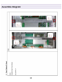
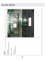
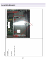
1
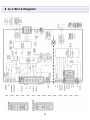
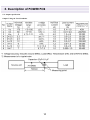
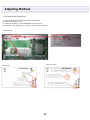
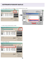
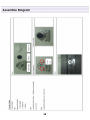
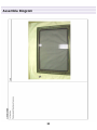
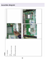
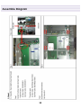
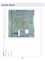
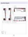
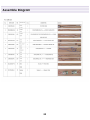
S/M NO : PASP42B001
42” PLASMA PDP TV
PASP42B3D3S0
DPX-42D1NMSB
DPX-42D1
1
CONTENS
1. Safety Precautions
2. Product Specification
2-1. DPX-42D1NMSB Product Specification
2-2. Available input signal
3. Block Diagram
3-1. Basic Block Diagram
3-2. Panel Block Diagram
4. A/V Block Diagram
5. Description of POWER PCB
5-1. Input/Output pin assignment & specification
5-2. Output specification
6. Service Mode
6-1. ENTERING METHODE OF SERVICE MODE
6-2. DEFAULT VALUE OF SERVICE MODE
7. Adjusting Method
7-1. Adjusting WHITE BALANCE
7-2 . POWER BOARD Adjustment
8. SOFTWARE UPGRADE Method
8-1. Preparation
8-2. UPGRADE Method
9. SET Disassemble/Assemble Method
9-1. Facts You Must Know When Disassembling/Assembling PDP SET
9-2. PCB Disassemble/Assemble
9-3. FRONT MASK & FILTER GLASS Disassemble/Assemble Method
10. Main PCB Trouble Diagnosis
10-1. VIDEO & JACK PCB Trouble Diagnosis
10-2. Sound Trouble Diagnosis
10-3. Key & IR Trouble Diagnosis
10-4. Remocone Trouble Diagnosis
11. TROUBLE SHOOTING
12. ASSEMBLY LIST
13. EXPLODED VIEW
14. Assemble Diagram
2
1.Safety Precautions
(1) When moving or laying down a PDP Set, at least two people must be working.
towards the PDP Set.
Avoid any impact
(2) Do not leave the broken PDP Set on for a long time. To prevent any further damages, after check the
broken Sets condition, make sure to turn the power (AC) off.
(3) When opening the BACK COVER, turn off the power (AC) to prevent electric shock. When a PDP
is on, high voltage and high current exist inside the Set.
(4) When loosening screws, check the connecting position and type of the screw. Sort out the screws
and store them separately. Because screws holding PCB are working as electric circuit
GROUNDING, make sure to check if any screw is missing when assembling.
(5) If you open the BACK COVER, you will see a Panel Gas Exhaust Tube . If this part is damaged,
entire PDP PANEL must be replaced. Therefore, when working, be careful not to damage this part.
(6) A PDP Set contains different kind of connector cables. When connecting or disconnecting connector
cables, check the direction and position of the cable beforehand.
(7) When disconnecting connectors, unplug the connectors slowly with care. Especially when
connecting/disconnecting FFC (film) cables or FPC cables, do not unplug the connectors too much
instantaneously or strongly, and always handle the cables with care.
(8) Connectors are designed so that if the number of pins or the direction does not match, connectors will
not fit. When having problem in plugging the connectors, make sure to check their kind, position, and
direction.
3
2. Product Specification
2-1. DPD-42D1GMB Product Specification
ITEM
SPECIFICATION
1. GENERAL
1-1MODEL NO
1-2. CHASSIS NO
1-3. SCREEN SIZE
1-4. COUNTRY
1-5. RESOLUTION
1-6. REMOTE CONTROL
1-7. TUNING METHOD
DPX-42D1NMSB
PASP42B3D3S0
42”(16:9)
South America
852(H) X 480(V)
DDR-2020C03
FS
2. ELECTRICAL
2-1. VIDEO INPUT
2-2. Component INPUT
2-3. PC INPUT
2-4. HDMI INPUT
2-5. TV INPUT
1) COLOR STANDARD
2) ANTENNA IN
3) RECEPTION CHANNEL
4) IF & SUBCARRIER
2-6. SOUND INPUT
2-7. SPEAKER OUTPUT
2-8. AUDIO OUTPUT
2-9. POWER REQUIREMENT
2-10. POWER CONSUMPTION
2-11. RS-232 /USB CONTROL
2-12. FUNCTIONS
1) SCALING
2) OSD
3) ETC
COMPOSITE(NTST, PAL, SECAM, PAL-M/N,NTSC4.43) 2SETS
& S-VHS(50/60Hz) 1SET
1080 i, 720P, 480P , 480i, 576P, 576i
(Y, Pb/Cb, Pr/Cr COMPONENT SIGNAL) 2 SETS
15Pin D-Sub 1 SET (1280 x 1024 60Hz max.)
HDMI 1 SET
NTSC, PAL-M/N
ONE INPUT 75Ω Unbalanced (F-STANDARD)
VHF LOW : 48.25MHz ~ 160MHz. HIGH : 160MHz ~ 442MHz.
UHF
: 442MHz ~ 801.28MHz
PIF : 45.25MHz(NTSC)
SIF : 41.25MHz (NTSC)
Component 2SETS, COMPOSITE 2SETS, PC 1 SET,
HDMI(DVI) 1 SET
10W(R) + 10W(L)
Audio Line Out 1 SET
AC 100V~240V, 50/60Hz
340W
RS-232 (FOR SYSTEM UPGRADE) ,
HDMI : Wide / Panorama / Zoom / 14:9 / 4:3
PC : Wide / 4:3 / 1:1
TV, A/V, Component : Wide / Panorama / Zoom, 14:9 / 4:3
4 LANGUAGES(ENGLISH, FRENCH, SPANISH, PORTUGUESE)
STILL, SLEEP MODE, PICTURE MODE, SOUND MODE,
TIMER, SCREEN MODE, Blue Screen, PANEL PROTECTION
(Screen Wiper & Pixel Shift)
4
REMARK
Product Specification
ITEM
3. MECHANICAL
3-1. APPEARANCE
1) WITHOUT STAND
2) WITH STAND
3) CARTON BOX
3-2. WEIGHT
1) WITHOUT STAND
2) WITH STAND
4. OPTICAL
4-1. SCREEN SIZE
4-2. ASPECT RATIO
4-3. NUMBER OF PIXELS
4-4. DISPLAY COLOR
4-5. CELL PITCH
4-6. VIEWING ANGLE
5. USERCONTROL &
ACCESSORIES
5-1 CONTROL BUTTON(SET)
5-2. REMOTE CONTROL
5-3. ACCESSORIES
SPECIFICATION
WxHxD= 1,113.5 x 744 x 101.5 mm
WxHxD= 1,113.5 x 822 x 351 mm
WxHxD= 1,278 x 860 x 377 mm
29.5 Kg Net
38.5 Kg Net
42 inches(106.68 Cm)
16:9
852(H)X480(V)
16.77MILLION COLOR( RGB 8BIT)
1080㎛ x 1080㎛ x RGB
160DEGREE(VERTICAL/HORIZONTAL)
CH+ / CH- / VOL+ / VOL- / AV
POWER, MUTE, TV, PC/HDMI, AV.SEL, SOURCE, MENU, EXIT,
CH-, CH+, VOL-, VOL+, ENTER, CH.ADD, AVC, PIC.SIZE,
PIC.MODE, MTS, S.MODE, PIP, P.INPUT, P.POSITION, P.SIZE,
P.SWAP, STILL, 0~9, +100, PRE-CH, SLEEP, KEY LOCK
REMOCON, USER MANUAL, POWER CORD,
BATTERY X 2(AAA SIZE)
5
REMARK
Product Specification
2-2. Available input signal
6
3. Block Diagram
3-1. Basic Block Diagram
AC INPUT
AC100~240V 50/60 Hz
M+7V
D+3.3V
A+12V
A+6V
POWER
MUTE
Vs (170V ~ 190V)
Va (60V ~65V)
Vcc (+5v)
POWER BOARD
POWER
LVP
MAIN/AV BOARD
LVDS
OUT
PANEL
DISPLAY
7
Block Diagram
3-2. Panel Block Diagram
Display Data
(LVDS Input)
RA+
RARB+
RBRC+
RCRD+
RDRCLK+
RCLK-
Memory
Controller
Input
Interface
Controller
Driver
Timing
Controller
Display Data
Driving
Scan
Driver
Color Plasma Display Panel
852 X 480 Pixels
Address Driver
8
Common
Sustain
Driver
4. A/V Block Diagram
9
5. Description of POWER PCB
5-1. Input/Output pin assignment & specification
Output connector
Input connector
10
5. Description of POWER PCB
5-2. Output specification
Output Voltage & Load Condition
11
6. Service Mode
6-1. ENTERING METHODE OF SERVICE MODE
1 => MUTE => (RECALL
) => MUTE BUTTON on the remote control
(You can exit from Service mode by press power button on the remote control)
6-2. DEFAULT VALUE OF SERVICE MODE
(1) DEFAULT VALUE OF Color Control
DPX-42D1NMSB(Default Value)
Sub Brightness
123
Sub Contrast
100
Red Offset
122
Red Gain
122
Green Offset
117
Green Gain
100
Blue Offset
127
Blue Gain
119
(2) Calibration Mode
Do not adjust.
(3) Option Table Mode
Do not adjust.
(4) Device Adjustment Mode
Do not adjust.
(5) Heat Run Mode
Heat Run.
(6) Version
-. Version: Tango-Tri_D2 Ver -.--. Release Day: MONTH/ DATE / YEAR
-. Release Time: HOUR/ MIN/ SEC
-. Panel used time: DATE/ HOUR/ MIN (PANEL USEDE TIME)
-. Panel Name: PDP_PI42_####_SD
(7) Reset
RESET TV.
12
7. Adjusting Method
7-1. Adjusting WHITE BALANCE
(1) Input 5 STEP GRAY SCALE PATTERN to Video Input Terminal.
(2) Set the SCREEN MODE to NORMAL.
(3) Enter SERVICE MODE by inputting remote controllers [“1” => “MUTE” => “RECALL”=> “MUTE” BUTTON],
and then select “COLOR CONTROL” and check Default Values of SERVICE MODE Items.
(4) Attach WHITE BALANCE METER(FACTORY USE METER: CA-100) SENSOR to 80% Gray Scale part.
(5) Adjust WHITE BALANCE by varying R,G,B GAIN
-. Control R,G,B GAIN values so that the ranges are within Default Value10. If deviate from the range, classify the
SET disqualified.
-. Set color coordinate to x = 0.2800.01, y = 0.2900.01 and color temperature to above or equal to 10,000K.
(6) Attach WHITE BALANCE METERs SENSOR to 40% Gray Scale part.
(7) Adjust WHITE BALANCE by varying R,G,B BIAS-. Control R,G,B BIAS values so that the ranges are
within Default Value5. If deviate from the range, classify the SET disqualified.-. Set color coordinate to
x = 0.2800.01, y = 0.2900.01.
(8) Repeat above (4) ~ (7) until color coordinate is x=0.280, y=0.290. Attach WHITE BALANCE METERs SENSOR to
100% Gray Scale part. Control SUB CONTRAST so that LUMINANCE is above or equal to 140 Cd/m2.
(9) Press “Power” button and Exit SERVICE MODE.
DPX-42D1NMSB(Default Value)
Sub Brightness
123
Sub Contrast
100
Red Offset
122
Red Gain
122
Green Offset
117
Green Gain
100
Blue Offset
127
Blue Gain
119
13
Adjusting Method
7-2 POWER BOARD Adjustment
(1) Turn On the PDP TV and Display Full white Pattern
(2) Check the Voltage Label
(3) Check the Voltage by using Multimeter each Test Point
(4) Adjust the each Voltage Very slowly, witted voltage at the label
Voltage Label
Test Point
Adjust Volume
14
8. SOFTWARE UPGRADE Method
8-1. Preparation
(1) IBM PC with Serial Port (D-Sub 9 Type)
(with Windows98, Windows ME, Windows NT, Windows 2000, Windows XP)
(2) Update Cable (D-sub 9 pin mail to Phone Jack)
8-2. UPGRADE Method
(1) Check the com port is available. if com port is not available, you must install com port.
(2) Plug out power cable form PDP TV’s Power inlet.
(3) Connect phone jack to PDP TV’s upgrade port.
(4) Connect D-sub 9pin jack to computer com port.
(5) Run PC’s Flashexpress_nologo.exe
15
SOFTWARE UPGRADE Method
(6) Select Upgrade folder by pressing
button and Select firmware folder
(7) Select COM port and baud rate(1152000)
(8) Select WARE3.INF.
16
SOFTWARE UPGRADE Method
(9) Press the
button and plug in power code to PDP’s power inlet.
(10) When all files Upgrade are complete, “Download successful” (below) will come out.
(11) Check Firmware Version and reset PDP TV.
* Reset method
1. Turn on the TV
2. Enter Service mode(1 -> Mute -> Recall -> Mute.)
3. Check Firmware Version. (Select “6. Version”)
4. Reset. (Select “7. Reset”)
17
9. SET Disassemble/Assemble Method
9. SET Disassemble/Assemble Method
.9-1. Facts You Must Know When Disassembling/Assembling PDP SET
(1) The sheet must be clean, smooth and thick enough to reduce any impact which might occur while handling.
(2) BACK COVER can’ t be opened without separating the STAND from the PDP SET.
(3) BACK Shield Case can’ t be opened without separating the KEY PCB
(4) When disassemble PDP set. Do not disassemble Frame Main L/R screw, that may be cause of drop PDP Panel.
(5) When working with SET standing, be careful not to let screws or PCBs drop inside SET.
(6) Screws, connector cables, and other tools must be kept separately for reassemble.
9-2. PCB Disassemble/Assemble
(1) Detach BACK COVER
(2) Detach KEY PCB and then disassemble cable from KEY PCB.
(3) Detach LED-IR PCB and then disassemble cable from LED-IR PCB.
(4) Detach BCK SHIELD CASE L/R
(5) Detach POWER PCB
Disconnect cable from POWER PCB >>Unscrew POWER BOARD
(6) Detach VIDEO PCB
Disconnect cable from VIDEO PCB >>Unscrew VIDEO BOARD & TERMINAL
(7) Assembling procedure is in the reversing sequence of the disassembling procedure.
9-3. FRONT MASK & FILTER GLASS Disassemble/Assemble Method
(1) Detach BACK COVER.
(2) Detach KEY PCB and then disassemble cable from KEY PCB.
(3) Detach LED-IR PCB and then disassemble cable from LED-IR PCB.
(4) Detach BCK SHIELD CASE L/R.
(5) Unscrew the lower 4 screw and upper 4 screw at the PANEL BRACKET L/R
(6) Disassemble the PANEL from FRONT MASK.
(7) Detach the Retainer. (TOP, BOTTOM, LEFT, RIGHT)
When assemble Retainer. Must use new Gasket & new cushion tape.
(8) Detach FILTER GLASS.
(9) Assembling procedure is in the reversing sequence of the disassembling procedure.
(CAUTION) Before assemble
(1) Check front and back of FILTER GLASS. Make sure front is facing FRONT MASK’s external view.
(2) Be cautious of FILTER GLASS not being stained with dust or extraneous material. Clean FILTER GLASS with a clean
and soft cloth before assembling.
18
10. Main PCB Trouble Diagnosis
10-1. VIDEO & JACK PCB Trouble Diagnosis
Check Start
NO
Does “No signal”
screen appear?
Is there a weak
discharge
on the screen?
YES
1. Confirm AC connection
2. Confirm Cable connection
of Power PCB
3. Reassemble or change
Power PCB
NO
YES
NO
Is the signal input Jack
correctly connected?
Check the connection of
Jack (PDP or AV device)
Is the LVDS Cable
correctly connected?
YES
1. Confirm Cable connection
of Video PCB
2. Reassemble or
change Video PCB
NO
YES
NO
Check A/V Device
function
Does input source
(AV device) operate?
1. Check other PCBs
(DIGITAL,X/Y-SUS),
CONNECTION
2. Reassemble or change PA603
YES
Is input selection
in used mode?
NO
Confirm input
selection
10-2. Sound Trouble Diagnosis
Check Start
NO
Does screen appear?
1. Confirm AC connection
2. Confirm Cable connection
of Power PCB
3. Reassemble or change
Power PCB
YES
Is the sound power Cable
correctly connected?
YES
Confirm
speaker power Cable
connection
YES
NO
Is the sound input Jack
correctly connected?
Check the connection of
Jack (PDP or AV device)
YES
Is the sound Cable
correctly connected?
YES
YES
NO
Does input source
(AV device) operate?
Check A/V Device
function
Change Video PCB
or speaker
YES
19
Confirm
speaker cable
connection
Main PCB Trouble Diagnosis
10-3. Key & IR Trouble Diagnosis
Check Start
NO
LED light is appear?
1. Check the connection of
Key_LED_IR cable
2. Change the Key_LED_IR cable
3. Change IR_LED PCB
4. Change Video PCB
YES
Dose PDP TV turn on
by use remocone?
NO
1. Change IR_LED PCB
2. Change Video PCB
YES
Check the KEY Lock
function
OFF
1. Change KEY PCB
2. Change Video PCB
ON
Check A/V Device
function
10-4. Remocon Trouble Diagnosis
Check Start
LED light is appear?
NO
1. Check the connection of
Key_LED_IR cable
2. Change the Key_LED_IR cable
3. Change IR_LED PCB
4. Change Video PCB
YES
NO
Is battery available?
1. Change Battery
YES
Change Remocon
20
11. TROUBLE SHOOTING
11-1. Facts you must know when Trouble diagnosis or repairing
(1) Sets trouble diagnosis and repairing means Module Exchange. In other words, find out which PCB modules are not working and replace them with
normal PCB modules. Do not need to fix broken PCB modules in themselves.
(2) This TROUBLE SHOOTING list only contains representative and simple PCB trouble diagnosis and Module Exchange method. Therefore, if you find
Sets that are difficult to diagnose or to repair, contact Daewoo Electronics.
(3) Basic TROUBLE SHOOTING procedure Check Trouble Symptom Detach BACK COVER Trouble Diagnosis replace broken PCB module Adjust new
PCB module ( when replacing X-SUS, Y-SUS, POWER, VIDEOPCB, need Voltage adjustment) HEATRUN (for at least 30minutes, input TEST
PATTERN FULL WHITE), FUNCTION CHECK Repair Complete.
(4) Keep broken PCB modules separately for replacing with new PCB modules.
(5) Required equipments for trouble diagnosis- DIGITAL MULTIMETER (User Mode : measure DC VOLTAGE, measure DIODEVOLTAGE, SHORTOPEN TEST )- Screwdriver (or electric screwdriver), plastic adjusting tool
(6) Before assemble/disassemble PCBs, check to see if AC Switch is OFF.
(7) After the set is repaired, leave BACK COVER open for followings. Do HEATRUN for at least30 minutes by inputting SERVICE MODEs TEST
PATTERN (Refer to Service Manual 5.Service Mode) FULL WHITE. Check the screen condition and basic functions (remote control operation etc.).
(8) After BACK COVER is closed, redo HEATRUN for at least one hour by inputting FULLWHITE using SERVICE MODEs TEST PATTERN. Check the
screen condition and basic functions.
21
12. ASSEMBLY LIST
No
Part No.
Part Name
Discription
1
PASP42B3S3SD
Main+A/D board
PIONEER 42" B3 Panel, 218 AD board (SOUTH AMERICA)
1
2
PASP42B3S3SV
Main+A/V board
PIONEER 42" B3 Panel, 218 AV board (SOUTH AMERICA)
1
3
PAS-SIG6LIXA
LED_IR BOARD
T=1.6*100*20/2L, IR&LED
1
4
PAS-SIG6KEYA
KEY BOARD
T=1.6*74*33.4/2L,KEY
1
5
DD-SP1AS06-1
Built in speaker cable ass'y
6
DD42NF02461
NOISE FILTER ASS’Y
2P*460/1P*150MM
1
7
DD42NR04451S
POWER 6P <--> 4P
4P*6P*450MM
1
8
DD42NR12401
POWER 7P/8P <--> 12P
12P*(7+8)P*400/400MM
1
9
DD42CO31501S
LVDS 31P
30P*31P*500MM
1
10
DD42CO14601
KEY_LED_IR CABLE
14P*8P*6P*(500*600)MM
1
11
DD42CO06701
Built in speaker cable
6P*(2+2)P*600+700MM
1
12
DD42NR04451
PANEL 4P CABLE
4P*4P*450MM
1
13
DD42NR10471
PANEL 10P CABLE
10P*10P*470MM
1
14
DDL32GND—40
GND CABLE
1P*200MM
15
DP4260M120A2
Font Cover
Mold/HIPS/3.5T/2Tone
1
16
DP4260M115A
Speaker Grill-B
Mold/ABS/3.5T/Silver
1
17
DP4260M113A
Speaker Elbow
Mold/ABS/2.0T/Silver
2
18
DP4260M121A
Back Cover
Mold/ABS/3.5T/Black/DW
1
19
DL3280M181BA
Knob Contl
Mold/ABS/Black
1
20
DL3280M190CA
Knob Stanby
Mold/ABS/Cr
1
21
DL3280M200A
Window IR
Mold/PA
1
22
DL3280M210A
Window Plate
Mold/Acryl/1.2T
1
23
DP4280E310A
Retainer-H
AL/1.2T
2
24
DP4280E320A
Retainer-V
AL/1.2T
2
25
DP4284P121A
PIO Panel Guide Bracket
EGI/PIO/1,OT
2
26
DP4211P122A
PIO Power Bracket
EGI
2
27
DP4281P123A
PIO SD Plate
EGI/2.0T
4
28
DP4280D330A
Mount Bracket-PDP
Diecasting
2
29
DP4280P340A
Stand Bracket PDP-Body
EGI/2.0T
2
30
DP4286P352A
Contl Shield
AL/0.8T/PIO/218/3System
1
31
DP4280P360A
Main Shield-L
EGI/0.5T
1
32
DP4280P370A
Main Shield-R
EGI/0.5T
1
33
DP4285P382A
Av Cover
SPTE/0.5T/218/3System
1
34
DARC-4
Retainer Coil
ID∮5.1,L=75
3
35
DP4200R672A
Top Cushion
Sponge Form/5.0T*895L*8W
2
36
DP4250R672A
Side Cushion
Sponge Form/5.0T*520L*8W
2
37
DP4260S651A
Gasket Retainer-V
1.5T*7W*540L
2
38
DP4260S652A
Gasket Retainer-H
1.5T*7W*945L
2
39
DP4260S654A
Gasket Av Cover
1.5T*7W*565L
1
40
DP4260S655A
Gasket Mount
1.5T*7W*100L
4
Qt'y
2
22
ASSEMBLY LIST
No
Part No.
Part Name
Discription
41
DP4260S653A
Gasket Shield
1.5T*20W*600L
1
42
DP4200S654A
Insulation Sheet-S
Non-woven fabric/0.8T/15W*45L
4
43
DP4210S655A
Insulation Sheet-L
Non-woven fabric/0.8T/25W*440L
1
44
DP4260S640A
Pad Top/R
EPS/30T
1
45
DP4260S650A
Pad Top/L
EPS/30T
1
46
DP4260S660A
Pad Bottom/R
EPS/30T
1
47
DP4260S670A
Pad Bottom/L
EPS/30T
1
48
DP4260S647A
Pad Top
PE/Form
1
49
DP5000S672A
Poly Bag
LDPE 0.5T*W1010*L960
1
50
DP4210J923A
Screw-Poly Bag
PE/60*160*0.07
1
51
999000001200
Accessory Bag
Vinyl/0.3T*W245*L360
1
52
DP4260B614C
AV Label
Audio Video Jack Label/218/3System
1
53
DP426-DW-01
Packing Box
Daewoo/Maxico
1
54
P-MB-30-0160
Mark Brand
Daewoo/Latin america
1
55
DP4260M171SA
Stand Cover
42"/ABS/Silver
1
56
DP4290D180A
Stand Arm
Diecasting/AL/Black/90
1
57
DP4290E190A
Stand Neck
Diecasting/Al/4290
1
58
DP4290E200A
Stand Bracket
Press/Al/4290
2
59
DP4280P210A
Stand Base
Press/EGI/3.0T
2
60
DP4260TR673A
Stand Rubber-B
42"/40*20*3T
4
61
DP4260TR674A
Stand Rubber-A
42"/40*20*6T
4
62
DP4280B698A
Stand Box-Out
DW2
1
63
DP4280B699A
Stand Box In-B
DW2
1
64
DP4280B700A
Stand Box In-A
DW2
1
65
P-MA-STD-113
Stand Manual
English
1
66
SM001
Machine Screw 3
WP+3*6
21
67
SM013
Machine Screw 3
S/W P/W-P+3*8Φ8
8
68
SM006
Machine Screw 4
P+4*6
4
69
SM002
Machine Screw 4
WP+4*8
16
70
SM003
Machine Screw 4
T/T-CT+WASHER+4*10
1
71
SM017
Machine Screw 5
S/W P/W-B+5*12Φ12
10
72
ST102
Taptite Screw 3
T/T-BP+3*5
2
73
ST107
Taptite Screw 3
TWP+3*6
4
74
ST108
Taptite Screw 3
TWP+3*8
20
75
ST101
Taptite Screw 4
T/T-BP+3*8
11
76
ST104
Taptite Screw 4
T/T-BP+4*8
44
77
ST140
Taptite Screw 4
T/S-2B+4*10
43
78
ST140
Taptite Screw 4
T/S-2B+4*10
11
79
SM011
Machine Screw 4
T*4*12
4
80
SM200
Machine Screw 5
S/W P/W-P+5*32
4
23
Qt'y
ASSEMBLY LIST
No
Part No.
Part Name
Discription
81
SM025
Machine Screw 5
S/W P/W P+5*16
2
82
SM008
Machine Screw 8
P+8*20
2
83
PBL4260DAE-01
Back Label
Paper
1
84
MA-BDWP--3S1
User manual
1
85
DPACC0000-10(EUROPE)
Power code
1
86
DPC9700000A(AAA)
Battery
2
87
RE-BLSIDEWA1
Remote controller
1
88
DP42B3MF01
PDP PANEL 42"-PIO B3
PDP PIONEER 42" B3 panel
24
Qt'y
1
13. EXPLODED VIEW
25
14. Assemble Diagram
26
Assemble Diagram
27
Assemble Diagram
28
Assemble Diagram
29
Assemble Diagram
30
Assemble Diagram
31
Assemble Diagram
32
Assemble Diagram
33
Assemble Diagram
34
Assemble Diagram
35
Assemble Diagram
36
Assemble Diagram
37
Assemble Diagram
38
Assemble Diagram
39
Assemble Diagram
40
Assemble Diagram
41
Assemble Diagram
42
Assemble Diagram
43
Assemble Diagram
44
Assemble Diagram
45
Assemble Diagram
46
47
Assemble Diagram
48
Assemble Diagram
49
Assemble Diagram
50
Assemble Diagram
51
Assemble Diagram
52
Assemble Diagram
53