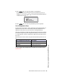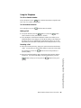
1
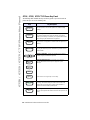
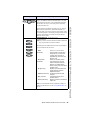
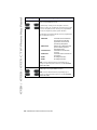
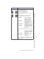
675xi Series
IP Phone
6753i - 6755i - 6757i CT
www.8x8.com | 1.866.879.8647
User
Reference
Manual
Copyright 2008 8x8, Inc. www.8x8.com
All Rights Reserved.
Table of Contents
Virtual Office Features ............................................................................................. 1
Introduction.................................................................................................................... 2
Phone Parts Checklist ................................................................................................... 2
Phone Parts ................................................................................................................... 3
6753i and 6755i IP Phone Parts ................................................................................ 3
6757i CT IP Phone Parts.............................................................................................. 4
6753i IP Phone Keys and Key Description............................................................... 6
Phone Features for the 6753i IP Phone .................................................................... 7
6755i IP Phone Keys and Key Description............................................................... 8
Phone Features for the 6755i IP Phone .................................................................... 9
6757i CT IP Phone Keys and Key Description......................................................10
Phone Features – 6757i CT Base Unit...........................................................11
Phone Features – 6757i CT Cordless Handset .........................................11
CM16E IP Phone Handset Keys and Key Description ........................................12
6753i / 6755i / 6757i CT IP Phone Key Panel............................................14
Installation and Setup ............................................................................................18
Direct or Shared Network Connection ....................................................................18
Direct Network Connection........................................................................................18
Shared Network Connection ....................................................................................19
Connecting to the Network and to Power ..............................................................19
Power Adapter ..............................................................................................................19
Connecting a Handset or Headset...........................................................................21
Desk or Wall Installation..............................................................................................21
Inserting the Key Card on your Phone .....................................................................24
Charging Cradle ...........................................................................................................25
Battery Installation and Charging..............................................................................25
Belt Clip ..........................................................................................................................26
Using a Headset with your Telephone .....................................................................26
Battery Status Icons.....................................................................................................27
Customizing your phone ......................................................................................27
Accessing Your Options via the Phone UI..............................................................28
Accessing Your Options via the 8x8 Web Phone UI ...........................................29
IP Phone Features....................................................................................................30
Adjusting the Volume...................................................................................................33
Status Lights (LEDs)....................................................................................................34
Call Timer........................................................................................................................34
6755i & 6757i CT Softkeys ...................................................................................34
iii
Table of Contents
Installation and Setup – 6757i CT Cordless Handset............................25
Table of Contents
Programmable Keys................................................................................................35
Creating a Speedial Key .............................................................................................36
Line/Call Appearance Keys ........................................................................................37
Using a Headset with your Telephone .....................................................................38
Using the Telephone ...............................................................................................39
To Call an Outside Number........................................................................................39
To Call Another Extension ..........................................................................................39
Making a Call .................................................................................................................39
Receiving a Call ............................................................................................................39
Notes ...............................................................................................................................40
Limited Warranty........................................................................................................41
What Is Covered? ........................................................................................................41
Support ..........................................................................................................................41
Table of Contents
iv
Introduction
Congratulations on the purchase of your 8x8 Virtual Office service and new
telephone. The phone has been manufactured to meet very high standards for
convenient and reliable service.
This telephone will operate according to the preloaded scripts. Please use the
interactive menu and soft buttons to access features provided by your 8x8 Virtual
Office Service.
Introduction
Model 675xi Series IP Phone User Guide — 1
Phone Parts
Phone Parts Checklist
Remember to save your sales receipt in case you ever need warranty service.
Check to make sure your package includes the items described below:
Telephone base
AC/DC adapter
Telephone handset
Wall mount bracket
Phone line
Handset cords
Phone Parts
When you unpack your phone, you should ensure that you have all of the
following items. Remember to save your sales receipt in case you ever need
warranty service.
2 — Model 675xi Series IP Phone User Guide
6753i and 6755i IP Phone Parts
Goodbye
Goodbye
Line 4
Options
Line 3
Hold
Line 2
Holed
Line 2
Redial
Line 1
Redial
Line 1
Options
Line 3
Speaker/
Headset
Speaker/
Heading
Mute
Mute
6753i IP Phone
or
6755i IP Phone
Wall Mount
Drilling Template
asdassa
asdadsda
Telephone Handset
Base Desk
Legs
Power
Adapter
Handset
Cord
Ethernet
Cable
Programmable
Key Card
Reference
CD
Wall Mount
Drilling Template
Screws and
Anchors for
Wall Mounting
Phone Parts
Model 675xi Series IP Phone User Guide — 3
Phone Parts
6757i CT IP Phone Parts
Line 4
Goodbye
Wall Mount
Drilling Template
Line 3
Options
Hold
Line 2
Redial
Line 1
Speaker/
Heading
Mute
Telephone Base
Power Adapter
(for 57i CT Base)
Ethernet Cable
asdassa
asdadsda
Handset
Power Adapter
Belt Clip
(for charging cradle)
Telephone Base
Desk Legs
Wall Mount
Drilling Template
Handset Cord
57i CT Cordless
Handset
Battery
Screws and
Anchors for
Wall Mounting
Charging Cradle
for Handset
Reference
CD
4 — Model 675xi Series IP Phone User Guide
675xi Optional Accessories (Not Included)
PoE
(Power over Ethernet)
Inline Power Injector
Model 536EM Expansion Module
Additional Ethernet Cable
(Category 5/5e straight
through cable)
Model 560EM Expansion Module
PoE (Power over Ethernet) Inline Power Injector
• A PoE (Power over Ethernet) Inline Power Injector supplies 48v power to the
675xi Series through the Ethernet Cable on pins 4 & 5 and 7 & 8.
Warning: Do not use this PoE Inline Power Injector to power
other devices.
The 536EM Expansion Module (536EM) and 560EM Expansion Module
(560EM) attaches to the right side of the 675xi Series phone. The 536EM
expansion module provides 36 additional softkeys for the phone. The 560EM
provides 60 additional softkeys. You can purchase the expansion modules from
our 8x8 accessories store at www.8x8.com/store.
The 6755i & 6757i CT can use either the 536EM or 560EM
expansion modules.
Model 675xi Series IP Phone User Guide — 5
Phone Parts
Note: The 6753i can only support the 536EM Expansion Module.
Phone Parts
6753i IP Phone Keys and Key Description
K ey Panel
6 keys with LEDs (4 are programmable)
High quality speakerphone
HAC handset
Goodbye
Options
Line 3
Hold
Line 2
Redial
Line 1
Speaker/
Heading
Mute
Goodbye key
Options key
Hold key
Redial Key
Volume control
Navigational keys
3-line LCD screen
Message waiting lamp
Keypad
Speakerphone/headset toggle key
Mute key
3 call appearance lines
6 — Model 675xi Series IP Phone User Guide
Phone Features for the 6753i IP Phone
• 3-line LCD screen
• 6 top keys: 4 are programmable keys
• 3 call appearance lines with LEDs
• Supports up to 9 call lines
• Full-duplex speakerphone for handsfree calls
• Headset support (modular connector)
• Built-in two-port, 10/100 Ethernet switch - lets you share a connection
with your computer
• Inline power support (based on 802.3af standard) which eliminates
power adapter
• AC power adapter (included)
• Enhanced busy lamp fields
Phone Parts
Model 675xi Series IP Phone User Guide — 7
Phone Parts
6755i IP Phone Keys and Key Description
Key Panel
6 keys with LEDs (4 are programmable)
High quality speakerphone
HAC handset
Goodbye
Line 4
Options
Line 3
Holed
Line 2
Redial
Line 1
Speaker/
Headset
Mute
Goodbye key
Options key
Hold key
Redial Key
Volume control
Navigational keys
3-line LCD screen
Message waiting lamp
Keypad
Speakerphone/headset toggle key
Mute key
4 call appearance lines
8 — Model 675xi Series IP Phone User Guide
Phone Features for the 6755i IP Phone
• 8 line graphical LCD screen (144 x 75 pixels) with white backlight
• 12 programmable keys
• 6 Top keys:
Programmable hard keys
(up to 6 programmable functions)
• 6 Bottom keys: Programmable state-based softkeys
(up to 20 programmable functions)
• 4 call appearance lines with LEDs
• Supports up to 9 call lines
• Full-duplex speakerphone for handsfree calls
• Headset support (modular connector)
• Built-in-two-port, 10/100 Ethernet switch - lets you share a connection
with your computer
• Inline power support (based on 802.3af standard) which eliminates
power adapters
• AC power adapter (included)
• Enhanced busy lamp fields
Phone Parts
Model 675xi Series IP Phone User Guide — 9
Phone Parts
6757i CT IP Phone Keys and Key Description
High quality speakphone
Message waiting lamp
12 softkeys
- 6 static
- 6 dynamic
HAC handset
Goodbye key
Options key]
Hold key
Redial Key
Volume control
Navigational keys
11-line LCD screen
Keypad
Speakerphone/headset toggle key
Mute key
4 call appearance lines
10 — Model 675xi Series IP Phone User Guide
Phone Features – 6757i CT Base Unit
• 11 line graphical LCD screen (144 x 128 pixels) with white backlight
• 12 multi-functional softkeys
• 6 Top Keys: programmable static softkeys (up to 10 programmable
functions)
• 6 Bottom Keys: programmable state-based softkeys (up to 20
programmable functions)
• 4 call appearance lines with LEDs
• Supports up to 9 call lines
• Full-duplex speakerphone for handsfree calls
• Headset support (modular connector)
• Inline power support (based on 802.3af standard) which eliminates
power adapters
• AC power adapter (included)
• Enhanced busy lamp fields
Phone Features – 6757i CT Cordless Handset
• 5 line backlit display screen
• 2 multi-functional softkeys
• Programmable function key supports up to 14 functions
• Vibration Alerter
• Headset Jack
• Desk charging stand
Model 675xi Series IP Phone User Guide — 11
Phone Features – 6757i CT Base Unit
• Built-in-two-port, 10/100 Ethernet switch - lets you share a connection
with your computer
Phone Features – 6757i CT Cordless Handset
CM16E IP Phone Handset Keys and Key Description
10
1
2
3
5
4
5
11
12
6
7
13
15
14
8
15
9
16
For use with the 6757 model only
Function #
Function Description
1
Receiver
2
Volume key
During Ringing: Adjusts ringer volume.
During a call: Adjusts receiver volume.
During text mode (not in a call): Moves cursor right/left.
3
Display
4
Features ƒ Key List
Access key to the programmed Feature Key List.
Scrolls up when in the various lists.
Adds a space during editing.
5
Softkeys
Activates feature or option shown on the display above the keys.
6
Call key
Used to obtain dial tone.
Also used as a Hold key.
7
Dialpad
8
Mute Key
When used, prevents the caller from hearing you.
12 — Model 675xi Series IP Phone User Guide
Function #
Function Description
Headset Jack
10
Status Light
11
Release Key
To end calls and go on hook.
Exits Menu and the various lists.
12
Menu Key
Access key to the different options.
scrolls down when in the various lists.
Used as backspace during editing.
13
Redial Key
Displays the last 10 numbers dialed.
14
Charging Jack
15
Charging Contacts
16
Microphone
Model 675xi Series IP Phone User Guide — 13
Phone Features – 6757i CT Cordless Handset
9
6753i / 6755i / 6757i CT IP Phone Key Panel
6753i / 6755i / 6757i CT IP Phone Key Panel
The following table identifies the keys on the key panel of your 675xi Series IP
phone that you can use for handling calls.
Keys
Goodbye
Key Description
Goodbye Key - Ends an active call. The Goodbye key also
exits an open list, such as the Options List, without saving
changes.
Options
Options Key - Accesses options to customize your phone.
Your System Administrator may have already customized
some of your settings. Check with your System Administrator
before changing the administrator-only options.
Hold
Hold Key - Places an active call on hold. To retrieve a held
call, press the call appearance button beside the light that is
flashing.
Redial
Redial Key - Redials up to 100 previously dialed numbers.
Pressing the Redial key twice simultaneously redials the last
dialed number.
Volume Control Key - Adjusts the volume for the handset,
headset, ringer, and handsfree speaker.
Line 1
Line/Call Appearance Key - Connects you to a line or
call. The 8x8 6753i Series IP phone supports up to 3
line keys.
Line 2
Line 3
Line 4
6755i & 6757i CT support up to 4 line keys.
Speaker/
Headset
Handsfree Key - Activates Handsfree for making and
receiving calls without lifting the handset. When the audio
mode option is set, this key is used to switch between a
headset and the handsfree speakerphone.
Mute
Mute Key - Mutes the microphone so that your caller cannot
hear you (the light indicator flashes when the microphone is on
mute).
14 — Model 675xi Series IP Phone User Guide
Keys
Key Description
Navigation Keys - Pressing the UP and DOWN arrow keys
lets you view different status and text messages on the LCD
display (if there is more than 1 line of status/text messages).
These buttons also let you scroll through menu selections,
such as the Options List.
6753i
Programmable Keys - Six Top Keys: 4 are
programmable keys.
Note: Keys 1 and 2 are hardcoded as the SAVE and DELETE
keys, respectively, and cannot be altered.
The following are the default functions for the programmable
keys on the 6753i Series IP phone:
1 - Save
(hardcoded)
Allows you to save numbers
and/or names to the Directory.
Using this key, you enter the
number, name, and line (or
speeddial key) to record in the
Directory List.
2 - Del (Delete)
Allows you to delete entries
(hardcoded)
from the Directory List and
Callers List. (Must enter the
Directory or Callers list and
select an entry, then press twice
to delete entry).
3 - Dir (Directory)
Displays up to 200 names and
phone numbers (stored in
alphabetical order).
4 - Callers (Callers List) Accesses the last 200 calls
received.
5 - Xfer (Transfer)
Transfers the active call to
another number.
6 - Conf (Conference)
Begins a conference call with the
active call.
Note: For more information about programming softkeys to
perform specific functions, see the "Programmable Keys" on
page 35.
Model 675xi Series IP Phone User Guide — 15
6753i / 6755i / 6757i CT IP Phone Key Panel
Pressing the LEFT and RIGHT arrow keys lets you view the
different line/call appearances. While in the Options List,
these keys allow you to exit or enter the current option. When
you are editing entries on the display, pressing the LEFT arrow
key erases the character on the left; pressing the RIGHT
arrow key sets the option.
6753i / 6755i / 6757i CT IP Phone Key Panel
Keys
6755i
Key Description
Programmable keys - 6 Top keys: programmable hard keys
(up to 6 programmable functions)
By default, keys 1 through 4 are assigned as Services,
Directory, Callers List, and Intercom, respectively. Keys 5 and
6 have no assigned functions. All 6 keys are programmable
and can be assigned to perform specific functions.
The following are the default functions for the programmable
keys on the 6755i IP phone:
1 - SERVICES
2 - DIRECTORY
3 - CALLERS LIST
4 - INTERCOM
5 - NONE
6 - NONE
Accesses enhanced features
and services such as XML
applications and voicemail,
provided by third parties.
Displays up to 200 names and
phone numbers (stored in
alphabetical order).
Accesses the last 200 calls
received.
Accesses another extension on
the network.
No assigned function
No assigned function
Note: For more information about programming keys 1
through 6 to perform specific functions, see the 8x8 Model
6755i User Guide.
6755i
Softkeys - 6 Bottom keys: programmable state-based
softkeys (up to 20 programmable functions)
Note: For more information about programming keys 1
through 6 to perform specific functions, see the 8x8 Model
6755i User Guide.
16 — Model 675xi Series IP Phone User Guide
Keys
6757i CT
Key Description
By default, keys 1 through 4 are assigned as Services,
Directory, Callers List, and Intercom, respectively:
1 - SERVICES
2 - DIRECTORY
3 - CALLERS LIST
4 - INTERCOM
Accesses enhanced features
and services such as XML
applications and voicemail,
provided by third parties.
Accesses the Directory List
which displays up to 200 names
and phone numbers (stored in
alphabetical order)
Accesses the Callers List which
lists the last 200 calls received.
Automatically connects with a
remote extension for outgoing
calls, and answers incoming
intercom calls.
The following softkeys display when you pick up the handset:
DIAL
CONF (Conference)
XFER (Transfer)
After entering a phone number
from the keypad, you can press
the Dial softkey to immediately
dial the number.
Begins a conference with the
active call.
Transfers the active call to
another number.
Note: For more information about programming the softkeys
to perform specific functions, see the 6755i & 6757i CT
Softkeys on page 34.
Model 675xi Series IP Phone User Guide — 17
6753i / 6755i / 6757i CT IP Phone Key Panel
Softkeys - 12 softkeys on the 6757i CT IP Phone.
• 6 Top Keys: static softkeys
(up to 10 programmable functions)
• 6 Bottom Keys: state-based softkeys
(up to 20 programmable functions)
All top and bottom keys can be configured for specific
functions.
Installation and Setup
Installation and Setup
The 675xi Series can be set up to share a network connection with another
network device. Power can be provided by the supplied power adapter or by an
802.3af compliant network power source or with a PoE Inline Power Injector
(optional accessory).
Direct or Shared Network Connection
The phone can be set up as a direct network connection to the Ethernet wall jack
or as a shared network connection as a pass-through if connecting the phone to
a computer or another network device.
Direct Network Connection
Located at the top of the phone are two fully switched 10/100 Mbps Ethernet
cable ports. The port marked with LAN is used to connect the phone to the
network, as well as provide power to your phone (if required).
Power Adapter
Connection
Network Jack
(if Inline power provided,
do not install the power adapter)
Ethernet
Cable
Separate
Network
Jack
Other Network Devices
18 — Model 675xi Series IP Phone User Guide
To Network
Power
Adapter
Shared Network Connection
To connect a network device (such as a computer) to the phone, connect an
Ethernet Cable into the network port on the top of the phone marked with PC.
Plug the other end of the Ethernet cable into the network jack on the network
device you are sharing the network connection with.
Note: The PC jack does not supply inline power onto other network
devices. All Ethernet cables used must be minimum category 5/5e
straight-through cables, such as the cable provided with your phone.
Connecting to the Network and to Power
Power Adapter
Use the power adapter (provided by your System Administrator) with your phone
and plug your phone into a power source.
Inline Power Provided
If your network provides 802.3af compliant in-line power, the phone is powered
through the network.
1. On the top of your phone, connect the Ethernet cable (provided with your
phone) into the network port marked with LAN.
Plug the other end of the Ethernet Cable directly into the network
jack on the wall.
To Network
Model 675xi Series IP Phone User Guide — 19
Installation and Setup
Ethernet
Cable
Network Jack
(if Inline power provided,
do not install the power adapter)
Installation and Setup
Inline Power Not Provided
If your network does not provide 802.3af compliant in-line power, you have to install the
power adapter or the PoE inline power supply (optional accessory).
1. On the top of your phone, connect the Ethernet cable (provided with your
phone) into the network port marked with LAN.
2. On the PoE power injector, plug the other end of the Ethernet cable into the
network jack marked as indicated in the following illustration.
3. On the PoE power injector, connect an additional Ethernet cable into the
network port as indicated in the following illustration.
4. Plug the other end of the Ethernet cable into the network jack on the wall.
5. Plug the PoE power injector into a power outlet.
PoE
Power injector
(if Inline power or the
power adapter are
not provided)
Ethernet
Cables
To PoE
Network Jack
Power Outlet
To Phone
To Network
Jack
Note: You should connect the power supply to a surge protector or power
bar. All Ethernet cables used must be minimum category 5/5e
straight-through cables, such as the cable provided with your phone.
20 — Model 675xi Series IP Phone User Guide
Connecting a Handset or Headset
Handset
Turn the phone over and locate the handset jack marked
. Insert one end of
handset cord into the jack until it clicks into place. Then route the handset cord
through the groove as shown in the illustration below. Attach the handset to the
other end of the handset cord.
To Headset
To Handset
Desk or Wall Installation
The desk installation for the 675xi Series IP phone consists of two legs that
attach to the back of the phone near the top corners. A total of four different
viewing angles allows users to personalize their phone viewing preference.
1. Attach each leg by inserting the tabs on the leg into the slots on the bottom of
the phone. There are three pair of leg slots on each corner of the phone; each
leg uses two pairs (1&2, or 2&3) giving two leg positions designating different
viewing angles. Furthermore, the legs can be reversed which offer two
additional viewing angles.
2. For a higher viewing angle, use the second and third slots from the top.
Model 675xi Series IP Phone User Guide — 21
Installation and Setup
Install on the Desk
Installation and Setup
3. For a lower viewing angle, use the first and second slots from the top.
4. Push the stand towards the phone until it snaps into place.
Three leg slot locations
for customizing the height
of the desk phone.
20.7 deg.
Incline Angle
23.3 deg.
Incline Angle
26.6 deg.
Incline Angle
Total 4 Viewing Angles
22 — Model 675xi Series IP Phone User Guide
30.9 deg.
Incline Angle
Install on the Wall
The 675xi Series IP phone has two pre-drilled wall mounting holes on the back of
the phone.
1. Using the provided wall mount drilling template, locate and mark the position
for the mounting screws on the wall. Depending on the wall type, you may
need to use wall anchors. Both the screws and wall anchors are included with
your phone.
2. Place the wall mount holes on the phone over the screw heads on the wall
and pull down to lock the phone in.
Note: You may wish to purchase a short Ethernet cable from a local supplier for a wall installation.
3. In the handset cradle, there is a small clip that sits flush with the cradle
surface. Using a small flathead screwdriver, pull the clip up and remove it from
the phone.
4. With the arms on the clip facing you and the flat side of the clip torwards the
phone, turn the clip 180 degrees and reinsert it back into the clip cavity in the
phone’s cradle.
Model 675xi Series IP Phone User Guide — 23
Installation and Setup
Wall Mount Holes
Installation and Setup
Inserting the Key Card on your Phone
This card contains the label identification spaces for (only for 6753i & 6755i)
programmable keys.
1. Remove the clear plastic lens from the top front panel of the telephone by
gently pressing down on the lens and sliding upward.
2. Place the card into the programmable key card slot on the top front panel of
the telephone using the indentation of the plastic for alignment.
3. With one hand holding the label card in place, gently slide the clear plastic
lens into the slots at the top of the programmable key panel.
6753i
6755i
24 — Model 675xi Series IP Phone User Guide
There are two steps involved in setting up the 57i CT cordless handset. The
charging cradle needs to be plugged in and the batteries need to be installed in
the handset.
Charging Cradle
The charging cradle is designed to be placed on a desk or any appropriate flat
surface. To set up the charging cradle:
1. Plug the modular cord of the power adapter into the jack on the bottom of the
cradle. Route the cord through the retaining tabs of the molded cord slot.
Verify the cradle rests on all four feet and doesn’t wobble.
2. Plug the other end of the power adapter into a non-switched AC outlet. It is
recommended that the adapter should not be plugged into an electrical
power bar and should be the only item plugged into the AC outlet.
Non-switched
AC Outlet
Battery Installation and Charging
The handset is powered by a nickel metal hydride battery pack. To install and
charge the battery:
1. Place the battery pack in the battery compartment with the connector wires
pointing towards the bottom of the handset
2. Connect the battery terminal wire to the charging pins within the battery
compartment
3. Slide the cover of the battery compartment from the bottom of the handset
until it locks into place
4. Place the handset, face up, in the charging cradle. The handset should easily
slide into the charging cradle. If it does not, check the battery compartment
cover to ensure it is properly closed.
5. Check the battery icon on the handset screen to confirm that it is blinking and
that the battery is properly charging.
Model 675xi Series IP Phone User Guide — 25
Installation and Setup – 6757i CT Cordless Handset
Installation and Setup – 6757i CT Cordless Handset
Installation and Setup – 6757i CT Cordless Handset
The cordless handset is automatically "factory paired" to the base station and
will establish contact with the base station once both units have been
successfully installed. This connection can be verified by checking for the
presence of the Reception range icon m beside the battery icon b on the
handset screen.
Note: The battery must be charged for a minimum of six hours prior to initial
usage of the handset.
Handset
(face down)
Belt Clip
To install the belt clip, snap one arm of the clip into the slot on the side of the
handset and then slide the other arm into the slot on the other side of the
handset until it snaps into place.
Using a Headset with your Telephone
The 6757i CT cordless handset accepts headsets through the jack on the
bottom of the handset. Contact your telephone equipment retailer or
distributor to purchase a compatible headset. Customers should read and
observe all safety recommendations contained in headset operating guides
when using any headset.
26 — Model 675xi Series IP Phone User Guide
Battery Status Icons
The display provides “at a glance” information on the handset battery:
The bars indicate the battery
charge level — 4 for full, needs
recharging when only 1 bar
appears.
The bars will flash when the
battery is being recharged on
the charger stand.
Note: The handset is designed to recharge the batteries automatically,
when required and placed on the charger stand. The battery icon will
not flash and the handset does not charge every time it is placed on
the stand. If a defective battery is replaced, then the battery icon is
not identified until the new battery is charged for at least 2 minutes.
Customizing your phone
A list of configuration options can be accessed by pressing the
button on
the phone and also via the 8x8 Web Phone UI as well. The following table
indicates the options and the method you can use to access these options on
your phone.
Options
Language
D
Time and Date
Time
Date
Time and Date Formats
Time Server
Time Zone
Daylight Saving Time
D
D
D
D
D
D
Ring Tone/Tone Sets
D
Clear Message Waiting
D
Contrast Level
D
Live Dialpad
D
Access from
8x8 Web Phone
UI
D
D
D
Model 675xi Series IP Phone User Guide — 27
Customizing your phone
Phone Option
Access from
Phone UI
Customizing your phone
Access from
Phone UI
Phone Option
Set Audio
Audio Mode
Headset Mic Volume
Access from
8x8 Web Phone
UI
D
D
Call Forward
Number
Mode
Number of Rings
D
D
D
Network
D
D
D
This is an Administrator option that is
password protected.
Phone Status
Network Status
Firmware Version
Restart Phone
D
D
D
D
D
D
User Password
D
D
Phone Lock
D
D
Accessing Your Options via the Phone UI
1. Press the Options key
Options
on the phone to enter the Options list.
2. To go to an Option, use
and
to scroll through the list, or press the
number corresponding to the Option.
3. Press the Show softkey, the
button, or press the digit number of the
corresponding option to select an option.
4. Use the softkeys to change a selected option.
5. Press the Done softkey at any time to exit the option and save the change.
6. Press the Cancel softkey, the
without saving changes.
button, or the N button at any time to exit
28 — Model 675xi Series IP Phone User Guide
Accessing Your Options via the 8x8 Web Phone UI
You can use the following procedure to access the phone options using the 8x8
Web Phone UI.
8x8 Web Phone UI
1. Open your web browser, enter the phone’s IP address or host name into the
address field and press <Enter>. The following logon screen displays.
.
The Network Status window displays for the IP phone you are accessing.
Note: For a user, the default user name is “user” and the password field is
left blank.
.
Model 675xi Series IP Phone User Guide — 29
Customizing your phone
2. At the prompt, enter your username and password and click
IP Phone Features
3. You can logout of the 8x8 Web Phone UI at any time by clicking Log Off.
The side menu options that display in the Network Status window are dependent
on whether you log in as an Administrator or User. A longer list of options
displays in the side menu for an Administrator.
IP Phone Features
Language
Select a language that you would like your phone to use for displaying prompts
and menus.
Note: Supported languages may vary depending on configuration. Contact
your Network Administrator for a list of available languages.
Time and Date
Use these options to set the local time on the phone. Depending upon the
configuration, time set here may be overwritten by the time on your phone
system. If you are having problems with this, contact your Network
Administrator.
• Time Server
Talk to your Network Administrator before making changes to this option.
If the Time Server option is enabled, the display shows the IP address where
the phone is getting time and date information from on the Network. Whenever
the phone starts up, it will automatically attempt to find the Time Server. If the
Time Server is not found and unknown to the phone, the IP address will
display as 0.0.0.0, and the time and date in the main screen displays the
equivalent of “12:00 am Jan. 1st 2000". If the Time Server option is disabled,
the display shows “Network Time Disabled”. You can set the time and date
manually on your phone.
• Set Time
This option shows the Network time, if the Time Server option is enabled. It also
allows you to set the time manually.
Note: If you set the time manually, the phone will not try to synchronize the
time with a time server until the next time it is restarted.
• Time Format
Select a time format for how time displays on your phone (12h or 24h clock).
• Set Date
30 — Model 675xi Series IP Phone User Guide
This option shows the Network date, if the Time server option is enabled. It also
allows you to enter the date manually.
Note: If you set the date manually, the phone will not synchronize the date
with a time server until the next time it is restarted.
• Date Format
Choose from a list of formats for how the date displays on your phone.
• Time Zone
Choose your current time zone. Select your country by scrolling through a list, or
by entering the country code (i.e., CA, US), then pick from the time zone list for
that country.
• Daylight Saving
This option allows you to specify daylight saving.
Ring Tone/Tone Set
Use these options to set the preference of ring tone and call progress tones for
your phone.
• Ring Tone
Press the Change softkey to select one of the five ring tones or silent. Use the
volume bar to increase or decrease the ringer volume level.
• Tone Set
Press the Change softkey to select one of the seven predefined tone sets for the
phone to play country specific call progress tones such as dial tone, ringing tone,
busy tone, congestion tone, call waiting tone, and ringing cadence.
Clear Message Waiting
Contrast Level
Use these options to set the preference of contrast level for your phone.
• Contrast Level
Use the Change softkey to cycle through eight contrast settings, which brighten
or darken the display.
Live Dialpad*
This option turns the Live Dialpad mode ON or OFF. With live dialpad ON, the
675xi Series IP phone automatically dials out and turns ON Handsfree mode as
soon as a dialpad key or softkey is pressed. With live dialpad OFF, if you dial a
number while the phone is on-hook, lifting the receiver or pressing the
initiates a call to that number. Press the Change softkey to turn ON or OFF the
dialpad mode.
Speaker/
Headset
*Availability of feature dependent on your phone system or service provider.
Model 675xi Series IP Phone User Guide — 31
IP Phone Features
To clear the Message Waiting Light, select the Clear softkey. The light will flash
again when there are new messages waiting.
IP Phone Features
Set Audio
The 675xi Series allows you to use a handset, a headset, or handsfree to handle
incoming and outgoing calls. The audio mode option provides different
combinations of these three methods to provide maximum flexibility in handling
calls. There are four audio mode options to choose from:
Audio Mode Option
Description
Speaker
This is the default setting. Calls can be made or received
using the handset or handsfree speakerphone. In handset
audio mode, pressing the
button on the phone
switches to handsfree speakerphone. In Speaker audio mode,
lift the handset to switch to the handset.
Speaker/
Headset
Headset
Choose this setting if you want to make or receive all calls
using a handset or headset. Calls can be switched from the
handset to headset by pressing the
button on the
phone. To switch from the headset to the handset, lift the
handset.
Speaker/
Headset
Speaker/Headset
Incoming calls are sent to the handsfree speakerphone first
when the
button is pressed. By pressing the button
again, you can switch back and forth between the handsfree
speakerphone and the headset. At anytime, lifting the handset
switches back to the handset from either the handsfree
speakerphone or the headset.
Speaker/
Headset
Headset/Speaker
Incoming calls are sent to the headset first when the
button is pressed. By pressing the button again, you can
switch back and forth between the headset and the handsfree
speakerphone. At anytime, lifting the handset switches back to
the handset from either the headset or the handsfree
speakerphone.
Speaker/
Headset
Headset Mic Volume
To adjust the headset microphone volume, press Advanced after selecting the
audio option, and then select the Low, Medium, or High volume level.
Call Forward
Use this option to call forward your phone. Use the
and
buttons to
move between the fields to set the call forward Number, Mode, and No. Rings.
The selectable call forward mode includes: All, Busy, NoAns (No Answer),
BusyNoAns (Busy No Answer), or Off; this is selected via the
and
buttons.
Phone Status
This option allows you to:
• View your network status including your phone’s IP and MAC address
• View your firmware version
• Restart your phone
32 — Model 675xi Series IP Phone User Guide
There is also a system administrator level-only option to reset the phone to
factory default settings. See your system administrator for details.
User Password
Use this option to change your user password. Valid values for entering a
password are 0 to 4294967295 (integers only; symbols and alpha characters
are not allowed). Default password is an empty string "" (field is blank).
Phone Lock
Use this option to lock the phone from unauthorized users. When the phone is
locked, users are unable to dial from the phone unless it has been unlocked. To
unlock the phone, press the
button and enter either the user or
Options
administrator password.
Note: While the phone is locked, only emergency number dialing is
permitted. The default permissible emergency number is 911, this
is configurable via the 8x8 Web Phone UI or configuration file.
Hint: To quickly lock your phone, press the
Options
button followed by the
key.
Adjusting the Volume
Pressing the volume button
and ringer volumes.
adjusts the receiver, headset, speaker,
• To adjust the ringer volume, leave the handset in the cradle and press the
volume button
while there is no active call. There are 10
settings for the ringer including Off — the display will temporarily indicate
the current ringer volume setting.
• To adjust the headset volume, press the volume button
while the
headset is activated (activate the headset by pressing
; ensure
headset audio mode is set). The headset will remain at this volume until it is
adjusted again.
Speaker/
Headset
• To adjust the speaker volume, press the volume button
while the
speaker is activated (activate the speaker by pressing
; ensure
handsfree speakerphone audio mode is set). The speaker will remain at this
volume until it is adjusted again.
Speaker/
Headset
Model 675xi Series IP Phone User Guide — 33
IP Phone Features
• To adjust the handset volume, lift the handset and press the volume button
while the handset is off hook. The handset will remain at this
volume until it is adjusted again.
6755i & 6757i CT Softkeys
Status Lights (LEDs)
The speaker LED, beside the
key, and the Message Waiting Indicator
(MWI) LED, on the top right of your phone, provide visual indications of your
phone’s status.
Speaker/
Headset
Speaker LED
Speaker LED Status
Description
ON solid
Indicates a call is on Handsfree (speakerphone).
Slow Flash
Indicates you are using the headset.
Rapid Flash
Indicates the call is muted. Press
mute.
Mute
to take the call off
Message Waiting Indicator (MWI)
MWI LED Status
Description
Slow Flash
Indicates you have a message(s).
Rapid Flash
Indicates you have an incoming call.
Even Flash
Indicates one or more calls are on hold.
Call Timer
• When you make or answer a call, the Timer shows the elapsed time of
the call.
6755i & 6757i CT Softkeys
The 6755i and 6757i CT have 12 multi-functional softkeys:
• 6 Top Keys: programmable static softkeys (up to 10 programmable
functions)
• 6 Bottom Keys: programmable state-based softkeys (up to 20
programmable functions)
These keys are located at the center of the phone on either side of the
display panel. These softkeys make call handling and call managing easier.
You can set these programmable softkeys to perform specific functions and
access enhanced services provided by third parties (using XML). Other services
include accessing Directory and Call Logs. You must use the Packet8 Web
Phone UI to configure the programmable softkeys.
These keys can also be set up to quickly access features such as Do Not Disturb
(DND) or Voicemail.
For more information about programmable keys on the 6757i IP phone, see the
8x8 6755i IP Phone and 6757i CT IP Phone User Guides, or contact your
System Administrator.
34 — Model 675xi Series IP Phone User Guide
Programmable Keys
There are hard keys on the 675xi Series phone located at the top, left of the
front panel display. Keys 1 and 2 (SAVE and DELTE keys) are hardcoded and
cannot be changed. Keys 3-6 or 3-12 (depending on the model) are
programmable keys.
The following are the default functions for the programmable keys on the
675xi Series IP phone.
Feature
Model
User Interface
6753i
6755i
6757i CT Phone
Web
Ring Tone & Tone Set
(Refer to “Ring Tone/Tone Set” on
page 31.)
D
D
D
D
D
Contrast Level
D
D
D
D
Enabling/Disabling Live Dialpad
D
D
D
D
Audio Mode & Headset Mic Volume
D
D
D
D
Time & Date Format (Admin Only)
D
D
D
Time & Date Configuration
D
D
D
D
D
Language
D
D
D
D
D
User Password
D
D
D
D
D
Resetting User Password
D
D
D
Restart Phone for Updates
D
D
D
D
D
Phone Lock/Unlock
D
D
D
D
D
Line Key (Refer to “Line/Call
Appearance Keys” on page 37.)
D
D
D
Speed dial Key
D
D
D
Do Not Disturb (DND) Key
D
D
D
D
Busy Lamp Field (BLF) Key
(Asterisk ONLY)
D
D
D
D
BLF List Key (Admin Enabled)
D
D
D
D
Flash Key
D
D
D
D
XML Key (Admin Enabled)
D
D
D
Sprecode Key
D
D
D
D
D
D
D
D
D
D
D
D
D
Last Call Return (LCR) Key
D
D
D
D
Directory Key (Key 3 Default)
D
D
D
D
Callers List Key (Key 4 Default)
D
D
D
D
Model 675xi Series IP Phone User Guide — 35
Programmable Keys
Park/Pickup Key
D
Programmable Keys
Feature
Model
User Interface
6753i
6755i
6757i CT Phone
Web
Transfer Key (Key 5 Default)
D
D
D
D
Conference Key (Key 6 Default)
D
D
D
D
Intercom Key
D
D
D
None Key
D
D
D
Phone Lock Key
D
D
D
Deleting a Key
D
D
D
D
Voicemail
D
D
D
D
D
D
D
D
D
These keys can also be set up to quickly access features such as Do Not Disturb
(DND) and Voicemail.
You must use the 8x8 Web Phone UI to configure the programmable keys. For
more information about programming keys with other functions on the 675xi
series IP phone, see 8x8 675xi User Guides corresponding to your 8x8 IP Phone
model (6753i, 6755i, or 6757i CT).
Creating a Speedial Key
Pressing and holding down a programmable key on the phone initiates a
speeddial feature.
Note: When creating a speeddial key from the IP Phone UI, you must
select a programmable key that has no preassigned function (key
must be set to none or empty).
1. Press a programmable key on the keypad for 3 seconds. A screen displays
with the prompt, "Enter number>".
2. Enter a phone number or extension to assign to that speeddial key.
The following example illustrates the screen display:
Speeddial
Enter number> 3456
After entering the number, "Use Save to end" displays on the screen.
3456
Use Save to end
36 — Model 675xi Series IP Phone User Guide
3. Press
(Key 1) to save the number as a speeddial key.
By default, the phone automatically assigns the speeddial key to Line 1, if
available. You can use the
and
to change the speeddial information to
a different line if required.
Line: 1
Change
Use Save to end
4. Press
(Key 1) to save the speeddial key to the line specified.
Line/Call Appearance Keys
The 675xi Series has between 3 and 6 (depending on the model) hard/line call
appearance keys each with a corresponding status light. Additional line call
appearances may also be set up on your phone as programmable keys.
These line call appearance buttons and lights represent physical lines or calls for
your extension. By pressing a line call appearance button, you connect to the line
or a call it represents. The line call appearance light indicates the status of that
line or call.
When the phone is taken off-hook, the phone will automatically select a line for
you.
Description
OFF
Indicates idle line or no call activity
Rapid Flash
Indicates ringing on the line.
Slow Flash
Indicates a call is on hold.
You can configure Line/Call Appearance by logging into your 8x8 account at
www.8x8.com.
Model 675xi Series IP Phone User Guide — 37
Programmable Keys
Line Call Appearance LED Status
Programmable Keys
Using a Headset with your Telephone
The 675xi Series accepts headsets through the modular jack on the back of the
phone. Contact your telephone equipment retailer or distributor to purchase a
compatible headset. A non-amplified headset is required. Customers should
read and observe all safety recommendations contained in headset
operating guides when using any headset.
Note: For best headset performance, 8x8 recommends non-amplified
headset equipped with modular connector.
Making and Receiving Calls using a Headset
1. Ensure that you have selected a headset audio mode by accessing the Options
menu. See the section "Customizing your phone" on page 27 for detailed
information.
2. Plug the headset into the jack located on the underside of the phone marked
.
3. Press the
key to obtain dial tone or answer an incoming call.
Depending on the audio mode selected from the Options menu, dial tone
or an incoming call will be received on either the headset or the handsfree
speakerphone.
Speaker/
Headset
4. Press the N key to end the call.
38 — Model 675xi Series IP Phone User Guide
Using the Telephone
To Call an Outside Number
Speaker/
Headset
Pick up the phone or press
. Dial 9 and then the number (7-digit if in same
area code, or 9+1+area code+number).
To Call Another Extension
Pick up the phone or press
Speaker/
Headset
. Dial the extension number.
Making a Call
Speaker/
Headset
1. Pick up the Handset, press the
button, or press the
(when a headset is used), and listen for a dial tone.
Speaker/
Headset
button
2. Using the keypad, dial the desired telephone number. The number you are
dialing will appear on the display as you dial. When making a call or talking on
the phone, the “In Use” light will light up indicating the phone is in use. This
light will also be lit whenever another phone on the same phone line is in use.
Receiving a Call
1. When you hear the phone ring, simply pick up the handset from the handset
cradle. You may also press the [Speaker] button to answer the call to enable
the speakerphone. Press the
[Answer] softkey.
Speaker/
Headset
button to answer using headset, or
2. When you are finished talking, replace the handset in the handset cradle to
end the call. If you have been talking using the speakerphone, press the
button to hang up. You may press the
any time.
Goodbye
button to hang up at
Model 675xi Series IP Phone User Guide — 39
Using the Telephone
Speaker/
Headset
Notes
Notes
40 — Model 675xi Series IP Phone User Guide
Limited Warranty
This warranty applies only to products purchased and used in the United States.
What Is Covered?
Any defect in materials or workmanship for one year. (See 8x8 Virtual Office
terms and conditions.)
Support
Web/FAQs: www.8x8.com/support/faqs
Email: [email protected]
Phone: 888-898-8733 and press option [1] for Virtual Office, then option
[2] for support.
Outside the U.S.: 408-687-4120
Limited Warranty
Model 675xi Series IP Phone User Guide — 41
Notes
Warning!
Toll fraud is committed when individuals unlawfully gain access to a customer’s
telecommunication system. This is a criminal offense. Currently, we do not know
of any telecommunications system that is immune to this type of criminal activity.
8x8, Inc. will not accept liability for any damages, including long distance
charges, which result from unauthorized and/or unlawful use. Although 8x8, Inc.
has designed security features into its products and services, it is your sole
responsibility to use the security features and to establish security practices
within your organization, including training, security awareness, and call auditing
to eliminate security risks.
Notice
While every effort has been made to ensure accuracy, 8x8, Inc. will not be liable
for technical or editorial errors or omissions contained within this documentation.
The information contained in this documentation is subject to change without
notice.
This documentation may be used only in accordance with the terms of the 8x8,
Inc. License Agreement.
If you’ve read this owner’s manual and consulted the online Troubleshooting
section at www.8x8.com and still have problems, please call
1-888-898-8733 for technical assistance.
www.8x8.com | 1.866.879.8647