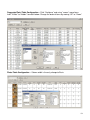
1
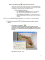
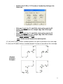
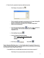
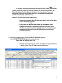
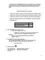
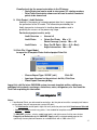
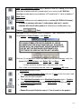
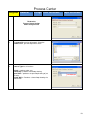
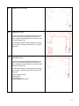
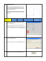
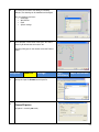
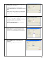
STEPS FOR ETEMPLATE PHOTO Version 2.3 PROJECTS
with CODED TARGETS
•
•
File | New Project (Project Wizard / Project Setup)
•
Select An Automated Coded Target ETemplate project…Next
Consists of…Next
• Default Settings…Next
1
Double left click the specific
cam file or highlight it and click
Open
•
To enter .cam or .pmr click Browse and navigate to the .cam, double left
click it, and click Next
•
Camera Review…Next
2
•
Photo Import Wizard dialog box: specify initial set of photos…
Click Add/Remove Images button
•
Add/Remove Photographs dialog box: click Change Directory button to find
Photo Source Directory and Select an Image File by double left clicking it.
3
•
TIP:
Select the images and click
to add selected images into the
project (or click ALL) | Click OK
CHOOSE IMAGES CAREFULLY
Choose and look for best images, meaning ones with overall largest number of placed
markers, and best opposite angles of all markers.
Remember, if Coded Targets are placed well and photos are shot taking the 6/1 Rule
of Overlap into consideration, a well-chosen group of photos can be automatically
processed quickly. Trying to process larger quantities of photos may result in time
consuming manual marking, referencing, and processing. Too many unnecessary
photos run through the wizard may require troubleshooting.
6/1 RULE
There must be 6 or more points shared between each photo and one other photo, and
1 or more points shared between each photo and two other photos in order for all
photos to become completely processed and oriented.
4
Click Next
•
Check Setting Distance Constraints
•
Click Next
•
Modify the Maximum center target size (pixels):
to
60
•
Modify the Minimum center target size (% of max):
to
15
•
Click Next
5
•
•
•
Check Translate/Active – Enter X1 Edge Marker Code in Coded Target
Number (keep X, Y, and Z values 0.0)
Checkmark Rotate | Active
Click Next
•
Enter the codes from the rotation markers in your Intelli-Kit to define
Automatic Rotation:
Horizontal – X Left to right
Vertical – Y Front to back
Code ID 1 = X1 code
Code ID 1 = Y1 code
Code ID 2 = X2 code
Code ID 2 = Y2 code
•
•
Click Next
Setting Distance Constraints
The scales placed on a jobsite, must each be defined
separately as a constraint. By predefining 3 standard
scales in the settings file, the automated Project
Setup Wizard detects, marks and references the scale
ends, and automatically defines the constraint
distances. Each will be noted in the Automated
Coded Target Project Summary dialog box.
•
In place of Unnamed, type a new scale
name, ie: C1
6
For C1 distance constraint
• Fill in
Pt. 1 ID
Pt. 2 ID
Distance
•
•
•
Highlight Unnamed on right
Type scale name, ie:
C2
•
•
Highlight Unnamed on right
Type scale name, ie:
C3
Click ADD
For C2 distance constraint
• Fill in
Pt. 1 ID
Pt. 2 ID
Distance
•
25
26
46 in.
27
28
46 in.
Click ADD
For C3 distance constraint
• Fill in
Pt. 1 ID
29
Pt. 2 ID
30
Distance
•
46 in
Click Next
7
NOTE: If Add is clicked after defining the last constraint, the following will result:
The Unnamed Constraint must be Deleted before clicking Next.
Ignore this area
•
To save a settings file for use with all new Automated Coded Target Projects
photographed with the same camera, Click Browse
TIMESAVER
CREATING AND USING A SETTINGS FILE WITH ALL NEW PROJECTS ELIMINATES
REPEATING APPROXIMATELY 10 OF THE ABOVE STEPS. A SETTINGS FILE RETAINS THE CAMERA AND
PARAMETERS AS DEFAULTS AND TAKES THE USER FROM ‘CHOOSING A TYPE OF PROJECT TO “CREATE’”
IMMEDIATELY TO THE PHOTO IMPORT WIZARD (pgS. 3 &4), THEN TO FINISH.
8
•
Type a new File name for the settings file that will retain all default settings that
were chosen or created in the Project Setup Wizard windows. The settings file
name will be appended with .ini. Click Save.
•
Click Finished
SAVE FREQUENTLY
The selected images open with Intelli-Mark targets marked, and cascade one at a time to
the workspace with “not oriented” stated in each image window title bar. As each mark
in an image is referenced and the set of photos are processed, when a photo satisfies the
required 6/1 Rule of Overlap, it then becomes oriented, designated in the specific window
title bar. If all photographs satisfy the overlap requirements, then the ending error shown
in the Project Summary dialog reflects the 3D model results based upon the chosen set
of photographs.
9
•
Review the Automated Coded Target Project Summary Dialog box and make note
of the following under Processing Stage 1 Results:
Ending Error is less than .250 (or not)
Total # of 3D points in project
Rotation successfully applied (or not)
Constraints Results – Added (or not)
Project complete (or not)
•
Click Close
•
Click Save Project
– type in new name and verify the project is being saved
in the folder with the specific project photos
Click OK
•
Click Window | Tile
•
Click Window | Zoom to Fit All
10
When a project is completed by the Project Wizard and the ending error is less than a
.250 overall value of goodness, the user should determine if the project is ready for
export as a .dxf file by completing the following final Quality Assessment checks.
1. Check values:
Ending Error (Total error)
Largest Residual (pixels)
Tightness (in.)
Angle (degrees)
< .250 (Project | Project Status Report)
< .80 (Point Table | sort)
< .04 (Point Table | sort -- this is the most
important value in determining accuracy)
≥ 30º
2. Manually mark any markers that were not automatically marked on all photos
and make sure these manual marks are referenced to their matching markers
on other photos
Or
Check for any unreferenced ID points still remaining on only 1 Photo that are
needed for template creation. They must be referenced to a matching point on
at least a 2nd photo in order to be in the exported dxf file
∗
∗
Open a Point Table
To review unreferenced points sort PHOTOS column 1 time
How To View Selected Point Table items:
•
•
∗
Select all point ID rows showing only 1 photo number in Photos
column and right mouse click | click Open Photos Showing
Selected
Or
If all photos are opened and tiled to the workspace, select
Expand selection to all Windows and Close the Point Table
The Selected point(s) will be highlighted red in the photos
Determine if these ID pts are needed for template creation
If so, find the matching markers on photos that have not been
automatically marked
Use the following tools:
Manual Sub-pixel Target Marking
Referencing
Process
Save frequently
(Quick Reference Selected)
11
How To Use Referencing
∗
(Quick Reference Selected)
Quickly cross reference any number of same item across photographs by
selecting the same marker on open photographs using Select Items Mode
and holding the SHIFT key down for multiple selection
•
Click Quick Reference Selected
If the Quick Reference Selected succeeds, the selected
items are all referenced together and are unselected
If Quick Reference Selected fails, a warning message will
appear displaying reason for failure and the items will remain
selected
Note: You cannot Quick Reference Selected two items marked on the same photograph.
3. Check to make sure the X1X2/Y1Y2 rotation markers have been correctly
defined
∗
Click Project | Scale/Rotate
Verify that the X1/X2 designators have been placed left to right
and that the Y1/Y2 designators have been placed front to back, so as
to cross over the X axis in the (Cartesian coordinate system) positive
direction.
∗
Click Cancel, if correct
OR
12
∗
Redefine the X1/X2 or Y1/Y2 markers if needed by clicking on the
Rotate tab
∗
∗
Click one (1) point for X1, hold Shift, click another point for X2
Verify 2 similar markers on a straight edge, from left to right
Click Define
∗
∗
Click one (1) point for Y1, hold Shift, click another point for Y2
Verify 2 similar markers on a straight edge, from front to back
Click Define, Process and Save
NOTE: Do Not use wall markers for rotation points
X1 (left) and X2 (right) markers should be placed as far apart as possible on the same edge
X1 (front) and X2 (back) markers should be placed as far apart as possible on the same edge
Rotation
Definition
Examples
13
4. Check that the constraints have been defined correctly
∗
Click Project | Constraints List
∗
Check a specific constraint by selecting it in the list and clicking Edit
to view its Object point IDs and specified distance
Delete a constraint by selecting it in the list and clicking delete
Define a new constraint by:
∗
∗
1.
Click Constraint Definition Mode
click one (1) point on the first
scale, hold Shift, click the other end point (two markers are
highlighted red)
2.
Click Add New Constraint
3.
Verify in Constrain Properties dialog;
type is 2 points to be a given distance apart
default Scale Value is 46
click OK
4.
Click Process
Click SAVE
Repeat Constraint Definition steps 1 – 4 for all scales placed in a project if they are not
automatically defined by being automatically marked, referenced and processed through
the Automated Coded Target Project Wizard.
***USER MUST PROCESS & SAVE EACH CONSTRAINT BEFORE DEFINING ANOTHER***
∗
Click Cancel if no new constraints need to be defined
14
∗ To visually check constraint point IDs open a Point Table
and sort
(SORT column by clicking in column header) the Constraints column. All
Point IDs defined as Constraints will have a 1 in the column. There will
always be twice as many ID rows with 1s as the number of constraints.
(column should only show 0s or 1s)
How To View Selected Point Table items:
•
•
Select all constraint point IDs and right mouse click | click Open
Photos Showing Selected
Or
If all photos are opened and tiled to the workspace, select
Expand selection to all Windows and Close the Point Table
The Selected point(s) will be highlighted red in the photos (this
technique can be used to visually check for misreferenced
constraint points)
5. Check the highest value of the LARGEST RESIDUAL (pixels)
Sort LARGEST RESIDUAL (pixels) column 2 times
Check that the Highest value <.80
Follow up if necessary, to reduce the highest Largest Residual
points to less than .80 and re-process and save
15
Zoom up on the red highlighted marker in each photo to try to determine
if the photo listed in the Photo Largest Residual column is really where the
point needs to be deleted or remarked and referenced, and then process
again
Zoom by doing one of the following:
• mouse over a marker, then press and hold ALT key for a temporary zoom
• mouse over a marker, then use the mouse scroll button to zoom in or out
• mouse over a marker, and press the plus or minus key on the keyboard
• pick one of the Zoom tools or use one of ETPhoto’s shortcut Keys from
its Window menu
Enter Zoom In mode
Enter Zoom Out mode
Enter Zoom Area mode
Zoom Previous
I
O
U
Y
6. Sort TIGHTNESS (in.) column 2 times
Check that the Highest value <.04
Follow up if necessary, to reduce highest Tightness (in.)
points to less than .04 and re-process and save
How To:
Same as steps in Largest Residual (pixels) follow up
Process and Save
7. Sort ANGLE for lowest Angle Separation
The minimum Angle(degrees) should be 30º, whenever possible
Any point ID under 10º will not be exported in the dxf file
•
Close Point Table
8. Open 3D viewer
Click Visibility tab
Click Settings tab
Click OK
Checkmark Camera Stations
Checkmark Orthographic
16
Visually check for the correct orientation in the 3D viewer
∗ Scale/Rotate tool can be used to view green X/Y rotation markers
∗ Point Table Constraints column can be used to select Constraint
points to be viewed red
9. Click Project | Audit Statistics
Auditing is the process of reviewing project data that is important to
the generation of the 3D model. The information provided by the
Audit step can be instrumental in tracking down problems and in
predicting the success of the processing stage.
For the best project results, verify:
Audit Overview >
Unused =0
Audit Photo
>
Points Per Photo: Min. = 15
Photo Coverage (%area): Min. = 30
Audit Points
>
Rays Per 3D Point: Min. = 2 (3 = Best)
Angle Intersection: Min. = 30
10. Click File | Export Model
to export an ETemplate Photo finished project Point Set
∗
∗
∗
Choose Export Type: 2D DXF (.dxf)
Click OK
Input new filename for the point set .dxf file, Click Save
Close Export Summary dialog
Import this .dxf file into a CAD/CAM system to create template outline, adding any
additional sink cutouts, overhangs, centerlines, notes, designators, etc. then send for
Tool Path or plotting for fabrication.
SAVE FREQUENTLY
Notes:
If two Marked Points are referenced to each other, but they do not mark the same physical feature
on the object, they will not generate a correct 3D point.
∗ To Unreference unclear points right click on a particular point and click Unreference Selected
∗ Select and Delete unnecessary points, if not needed for template creation
To UNCODE a marker, select a coded target point, and right mouse click for menu choice
Properties of Selected and click UNCODE | Apply and the selected coded target on the
specifically chosen photo will become an uncoded mark with a 1000 series ID #.
17
Additional ETemplate Photo tools
Use the AUTOMATIC TARGET MARKING tool to automatically mark photos being
added into a project.
Currently active photo (#) allows the
program to filter the active photo to find
any targets that may need marked
or
Photos from set allows the user to select
Photos from set Unoriented by clicking
Whole photo region (minus 10% outer
image frame) in the active photo is
filtered to be auto-marked
or
Pick Region in one photo by dragging a
window around a group of markers.
Mark Points for the chosen region.
Continue by dragging a second region
for the remaining markers, and mark
points again.
The Maximum Diameter, Minimum
Diameter and Circle Shape may need to
be modified to get all targets marked.
Use the " > " tool, next to Maximum
Diameter size to determine what
Maximum Diameter pixel setting to try.
18
Continue for each added photo.
After all photos are marked, Close the Automatic Target Marking dialog box, and clean
out any unnecessary marks by using the Select tool.
Press the Delete key on the keyboard and hold it, while moving around in a photo and
selecting the unnecessary marks. (select by clicking a single mark or draw a select
window around multiple marks to delete them).
NOTE: There may be some coded targets that cannot be found (either too small, too sharp an angle, not
enough of a gap between target and code ring or the code ring and background are too similar in
color/intensity). So it is a matter of making sure there are enough good coded targets in each image to do what
you want taking into account some of the targets might be missed. This also means that when the ‘Some’ option
above is used, when a coded target is missed you might end up with small code bits being marked as targets.
If a mark or group of marks is deleted by mistake, release the Delete key, move the
cursor to Edit (pull-down menu) | Undo Delete and the last deleted item or group of items
will reappear.
Continue until all photos have any unnecessary marks removed.
Use the AUTOMATIC REFERENCING tool to automatically reference marks being
added into a project.
•
•
•
•
•
•
1. All points in project
2. Parameters:
Set Search Distance. This value/# tells ETemplate Photo up to what
distance to search for other photo point locations. The default value
is the current highest Tightness (in.) value. A good rule of thumb is to
increase this value by a factor of 10 by removing the first '0' to the
right of the decimal point.
3. OK
4. Execute Referencing
5. Note the number of saved reference marks found.
Close; then Process and Save
19
DEFINING LAYERS AND MATERIALS (COLORS)
Use the LAYERS AND MATERIALS tools to set properties of a specific group of points
to a new layer name for easier access during the template creation
Click Layers
Click ADD & type Wall
click ADD & type Edge
click ADD & type Scale
OK
Select one name
Click Pick &
Select a Basic Color
Click OK
Repeat for each Layer
Click OK; OK
Click Materials
Click ADD & type Wall; click ADD & type Edge
click ADD & type Scale; OK
Next, to define the layers/materials, open only a few photos containing all markers
in project and ie: select all wall markers then click pull downs for correct name
To define the next layer/material, just begin to select the new type of markers and
repeat above step, pulling down for the correct Layer/Material names.
20
ETEMPLATE PHOTO PROJECT
PROCESSING CHECK LIST
REFS E C T I ON /P AG E
pg. 10
&
Sec. 1, pg. 11
AS SESSM ENT
SAVE FREQUENTLY
W H AT
T O C H E C K F OR
Automated Coded Target Project Summary Dialog
Total number of coded targets per photo = minimum 15 each
Ending Error [total overall value of goodness] < .250
Total number of 3D points in project
□ Successfully applied
□ Not Applied
Rotation
□ Successfully applied
□ Not Applied
Constraints Results: C1 – added □ C2 – added □ C3 – added □
Automated Coded Target Project □ Complete
□ Not Complete
Translate
Save new project name
Sec. 2, pg. 11
pgs. 18-19, 22
Targets-Marked
pgs. 12 or 19
Targets-Referenced
Sec. 2, pg. 11
Sec. 5, pg. 15
Sec. 6, pg. 16
All necessary targets have been marked
All necessary targets have been referenced and
processed -- Use Quick Reference Selected or
Automatic Referencing
Photos – Each ID row to show a minimum of 2 photos
Point Table
Columns
(Sort)
Sec. 7, pg. 16
Largest Residual – highest value < .80
Tightness (in) –
Angle (degrees) –
highest value < .04
lowest angle > 30º
X/Y Rotation
markers
& orientation
All 4 markers are marked, referenced and processed
Rotation is defined
Measure Mode
Double check length of a scale or field dimension
Constraints
Constraints List
Constraint Column on Point Table
Marks / Points
Layered / colors assigned
Sec. 8
pg. 16
3D Viewer
Rotation / view looks correct; all necessary points
are visible, layered, etc
Camera Stations show good angle separation
Sec. 9, pg. 17
Audit
Statistics
Verify minimum requirements & no unused points
Sec. 10, pg. 18
Export Model
Export 2D.dxf point set
Open or import in CAD/CAM software
Sec. 3
pg. 12-13
pg. 25
Sec. 4
pg. 14-15
pg. 20
21
Manual Tools of ETemplate Photo V2
Click Sub-pixel Target Mode
Mouse over marker, press alt to zoom in on Intelli-Mark, center cursor target
over a mark and click + drag box around mark, release mouse button,
release alt key; repeat for all marks
NOTE: If a mark is partially covered/blocked it should not be marked and used
because it may affect the Tightness (in.) value indicating a possible inaccuracy.
Click Reference
Select one (1) photo as Source (left side – Reference photo) and the other as
Destination (right side - Photo)
For referencing, select/highlight point(s) in Source photo using one of the
following three methods:
1
Single select by left mouse clicking a marker
Select window/box: by left mouse clicking + dragging a window around
multiple markers
(may select multiple windows/boxes, by pressing Shift to add to a selection)
3
Right click for pop-up menu in source photo and click Select All
4
Add to a selection by holding the SHIFT key down while continuing to
single select, or drag multiple windows
2
NOTE: Click Shift + F to maximize multiple photos to their workspace screens.
Bring mouse into Destination photo and (match) click appropriate point one
at a time – following yellow highlighted numbers in the source photo
NOTE: If highlighted point in Source photo is not in Destination photo –
press Esc to skip to the next selected point.
TIP : REFERENCING POINTS CORRECTLY THE FIRST TIME
SAVES TIME
Click Process to orient photos
Total processing error should be under .25 for good projects.
NOTE: If Point Table Quality Assessments are within their limits, the Total
processing error may be greater than .25 in some 4-5 photo projects.
22
ADD [File | Add/Remove Photos] only 1 photo at a time, or if adding 3-4 at a time
remember all photos marked "use and adjust" must satisfy the 6/1 RULE of
Overlap to enable processing to produce a 3D model and it's "value of goodness"
Mark, Save
Reference, making sure each added photo has at least [6/1 RULE of Overlap]
6+ marks in common with one (1) other photo, and has 1+ mark in
common with two (2) other photos for referencing to enable processing
Process,
, Save
Add scale if there is only one scale in the project. Open a photo with a scale in it.
Click Project > Scale & Rotate > click Scale tab
IF USING ETEMPLATE PHOTO VERSION 2.2, WE NO
LONGER USE THE SCALE FUNCTION. ALL SCALING IS
DONE WITH THE CONSTRAINT DEFINITION MODE TOOL.
(OR BY SETTING DISTANCE CONSTRAINTS IN A
SETTINGS FILE USED IN THE PROJECT WIZARD)
Click one (1) end point of a scale, hold Shift, click the other end point, verify the
appropriate Scale Distance, click Define, OK, and Save.
A scale cannot be used as both a constraint and a scale
Use 1 scale or if using more than one scale, use constraints, NO scale
Add Constraints instead of scale
1.
Click Constraint Definition Mode click one (1) point on the first scale, hold
Shift, click the other end point
2.
Click Add New Constraint and in Constrain Properties type is 2 points
to be a given distance apart, default Scale Value is 46.000, click OK
3.
Process and SAVE
-- Repeat Constraint Definition steps 1- 3 for all scales in the project --
23
Click Project > Scale & Rotate
(ignore Scale when using Constraints)
Click Rotate tab to define a flat plane needed for template
Define a flat plane:
Click one (1) point for X1, hold Shift, click another point for X2
Verify 2 similar markers are used on a straight edge, from left to right
Click Define
Click one (1) point for Y1, hold Shift, click another point for Y2
Verify 2 similar markers are used on a straight edge, from front to back
Click Define, Process and Save
Check Point Table
Largest Residual Pixel Size
Tightness (in)
should be under .80
should be .04 or less
Save project file intermittently and before continuing to the next step
***ROTATE MUST BE COMPLETED BEFORE FILE/EXPORT MODEL***
Set the property of a specific group of points to a new layer name for easier access
during the CAD template creation:
• select a group of points in photo(s) while holding down Shift key
• Right mouse click and select properties of selected
• Select material/layer tab
1. If a layer name has been added, use pull down to select layer name, click Apply and
then OK
2. If no layer name is defined, click Mark/Layer and then Add. Type in desired name, select
desired layer, click apply and OK
24
Troubleshooting with Point Audit Selected or Point Audit All
Select All photos & Open, then visually verify references are correct on each yellow highlighted
set of ID markers, Tag if not, for later correction or click NEXT in Audit box to continue
verification, until all point ID sets have been checked.
Use TAG while using the REFERENCING | POINT AUDIT ALL or SELECTED
tool, above, in order to note what point ID set needs troubleshooting.
Once an audit has been completed, and the dialog box is closed, a user can
right click on a “T” tag in a photo and select
OPEN PHOTOS SHOWING SELECTED
Or
If all photos are opened and tiled to the workspace, select
EXPAND SELECTION TO ALL WINDOWS
Close the Point Table
Selected point(s) will be highlighted red in the photos. The necessary action
can be done and the tag can be cleared by clicking
EDIT | CLEAR SELECTED or ALL TAG(s)
Use Measure Mode to check measurements between 2 markers on photos or
on the 3D Viewer point set, by selecting 1 marker, press & hold Shift, and
select the second marker for measurement between.
25
ETemplate Photo Reminders
Remember:
To add a new photo – it must have at least 6+ points in common with 1 previously
oriented photo, and have 1+ point in common with 2 other previously oriented photos
Note: Press the Alt key or use Zoom Icons/keys to help visualize problems.
To Unreference unclear points right click on the particular point and click Unreference
Selected or Select and Delete unnecessary points, if not needed for template creation
OR
Select a coded target point, and right mouse click for menu, select Properties of Selected and
click UNCODE | Apply and the selected coded target on the specifically chosen photo will
become an uncoded mark with a 1000 series ID #
IMPORTANT
Every marker needed to create a template drawing must be referenced and processed on
at least 2, 3 are better, photos. Points not cross-referenced appear on only one photo and
therefore, have no actual 3D location and will not appear in the final Exported file.
Template Creation
IF using Cadkey: Click CK19 desktop icon
•
In Cadkey select File > Import > AutoCAD dxf. Browse to find the exported file in the JOB
folder and Open the imported file of points
NOTE: IF SET OF POINTS APPEAR “SKEWED” EXIT CADKEY. OPEN ETEMPLATEPHOTO.
REORIENT POINT SET USING ROTATE AND EXPORT MODEL. IMPORT INTO CADKEY AGAIN.
•
Click M for countertop menu
IF not using Cadkey
Create the template drawing by importing or opening the DXF file in CAD/CAM application
ETemplate First !!
26
ETEMPLATE PHOTO EQUIPMENT
ITEM
DESCRIPTION
Intelli-Mark Wall Markers
Intelli-Mark Edge Markers
20 Markers – Set A or Set B
40 Markers – Set A & Set B
Intelli-Marks on Cardstock
12 cards – 2 Intelli-Marks per card
Intelli-Mark Scales
3 Scales
ETemplate Digital Measuring Camera
Step stool – NOT INCLUDED
Edge Locator Bracket for Remodels
To place edge markers on existing countertops
Standard Non-coded Target Markers
st
Standard ETemplate 1 Generation Markers or
Non-Standard Avery Markers
Carrying Cases
and notebook
In addition, you may want to bring additional items depending on your job requirements: White Board,
Notepad, Misc. Stickers (Avery Markers), and if necessary, other pre-determined measurement fixtures.
27
The significance of Intelli-Marks and how they are used
The Intelli-Marks are circular targets with a unique segmented ring-like bar code that is
automatically recognized by the ETemplate software process.
Wall Markers
Edge Markers
The two types of Intelli-Marks are Intelli-Mark stickers and Intelli-Mark Edge Markers. The
stickers are normally placed along the wall surfaces. The Intelli-Mark Edge Markers are
placed flat or standing on the ends/faces of the cabinets for all necessary profiles.
In addition to these two Intelli-Mark
types, you will also use Intelli-Mark
scales, which provide accurately
specified measurements.
Intelli-Scale
The following table shows the effects of temperature on the 46.00” aluminum scales. All materials are affected by
temperature. These scales have been designed to minimize changes due to temperature variations. When you are
in an environment with fairly extreme temperatures, it is a good practice to measure the scale to verify how it may
have varied. As you can see from the table below, temperature has only a minimal effect on the scale length. In
the vast majority of templates this will not affect your process. For large templates during extreme temperature,
you may want to measure the scale. When measuring the scale, be sure to measure from center of marker to
center of marker. When you do find small changes in the scale length, use the new value in the scale/constraint
functions.
Scale Temperature
Measurement Affect
90 degrees
+ .016 inches (1/64)
80 degrees
+ .008 inches
70 degrees
no change
60 degrees
-.008 inches
50 degrees
-.016 inches (1/64)
40 degrees
-.024 inches
30 degrees
-.032 inches (1/32)
28
Note the red box. Each Intelli-Mark has a unique segmented ring code and
number.
E-Template Locator Bracket Instructions
for quick and easy templating with existing tops on
For standard use – slide the tool (long
side up) until it reaches the cabinet edge.
Place your Intelli-Mark Edge Marker with
the short side facing front.
The center of your Intelli-Mark is now
directly over the cabinet edge.
For use with a drip edge top – slide the
tool (short side up) until it reaches the
cabinet edge.
Place your Intelli-Mark Edge Marker
with the long side facing front.
The center of your Intelli-Mark is now
directly over the cabinet edge.
29
The following table identifies each target marker and its use:
Table: Target number and use
Number
Use
1 – 24
Intelli – Marks provided on card stock for random use
25 & 26
Intelli – Marks: First Scale Points
C1
27 & 28
Intelli – Marks: Second Scale Points
C2
29 & 30
Intelli – Marks: Third Scale Points
C3
31 - 50
Set “A” Intelli – Mark Edge Markers
51 - 70
Set “B” Intelli – Mark Edge Markers
71 – 140
Intelli – Mark Wall Markers (Self Adhesive on Roll)
18 sets on a roll or 1260 total (Do not duplicate numbers in same jobsite)
141-161
Reserved for future use (These may be printed on card stock for extra marks)
1 - 161
Complete set of Intelli – Marks provided in .pdf file with system
IMPORTANT: Each Intelli-Mark has a unique number that is recognized and recorded into the point
table during processing. If a target is placed in a job more than once, it will cause referencing problems
during the processing phase.
30
Canon S90 Settings
Before turning on camera Menu Settings (screenshots)
– verify “Mode” dial is set
to “C”
The “C” setting is programmed for the
following settings.
Function Key Settings
6M 2816x2112 (M1) and “Normal”
setting
31
If you think your camera settings have been reset use the
following settings to verify.
Funct Set (button)
All settings are the default except:
M1 – Normal (6M 2816x2112)
Menu (button)
AF Frame Center
AF Frame Size Normal
Digital Zoom Off
AF-Point Zoom Off
Servo AF Off
AF-Assist Beam
On
MF-Point Zoom
On
Safety MF
On
Flash Settings Do not change
i-Contrast Off
Review 2 sec
Review Info
Off
Blink Detection Off
Custom Display
IS Mode Off (CRITICAL)
Date Stamp Off
Record Raw + L
Off
32
ETEMPLATE PHOTO
JOBSITE SETUP CHECK LIST
JOBSITE HARDWARE PLACEMENT
•
P lac e t ar ge ts ev e r y 1 2- 1 8” - - at le as t 2 p er ed g e
Intelli -- Marks
•
P lac e o n t op of c a b in e ts /c ou n ter to ps
(Coded Targets)
•
P lac e o n wa l ls /c ab i ne t f ac es
•
Mak e s ur e a t l eas t 1 5 c od e d tar g ets wi l l b e i n e ac h p h ot o
•
P lac e a l o ng wa l l( s ) as d es ir e d a n d o n c ab i n et f ac es f or r em ode l i n g
•
P lac e f l at or s t a nd i n g v er t ic a ll y o n en ds or f ac es of c a b in e ts f or al l
Intelli -- Marks
Stickers
Intelli -- Marks
Edge Markers
nec es s ar y pr of i l es ( i .e .: e d ge pr of i l e , s i nk c e nt er , etc .)
•
P lac e m ar k er s t o be u s ed as X 1 / X 2 ax is a n d Y1 / Y2 ax is ( m us t be
on s am e f la t p l an e)
Intelli -- Marks
•
Lie flat or on edge or angle, on cabinets or countertop
•
Place 1 scale EVERY 8-10 FT
(scale 40-50% of overall project linear length)
Scales
Additional
Information
•
Scales are Necessary for ACCURATE measurement
•
Use a small white board, notepads, or sticky notes placed
in photos to note all additional styles, reveals, or other
miscellaneous, necessary measurement information
Note: Use enough of above hardware items to insure each photo will contain a minimum
of 15 markers spread out across each complete image to insure that each photo will
satisfy the Rule of Overlap and facilitate automatic processing in the ETemplate Photo
software. The more common or overlapping points among photos and the better spread
of the markers across each complete image, the better chance for the automatic
processing wizard to complete the project.
See Process Center for more information on Job-site set-up
33
TAKING PHOTOGRAPHS
1.
Verify camera is set to ALL RESET ON
2.
DO NOT ZOOM OR USE THE TELEPHOTO button on camera
3.
ALWAYS Use Focus Lock when taking photos
--Press the shutter button half way down, then depress all the way down
4.
Each photo should contain at least 15 coded targets spread across the image
5.
Photos should be taken as close to 90° apart, as possible for each run/section
6.
Take 2 or more “overall” photos, from different horizontal/vertical angles (90° apart is best) with large
percentage of all project marks included. These overall photos help make a job process easier and faster by
requiring fewer photos to complete the actual processing.
7.
Close-up photos should cover at least 8-10 feet of countertop, with min. 15 points.
8.
Photos must be taken from physically relocated and widely separated positions for best camera station
rays and angles. Photos should be taken at varying height levels.
9.
Take a minimum of 3 photos; more (5 +) is better. Opposite angle, overall photos aid in easier and faster,
more accurate processing
10. Avoid taking photos with points in the 10% imaginary outer frame of the camera monitor screen. They
may be unusable due to large residual (pixels) values greater than .8.
11. Each marker point must be in at least 2 photos, 3 are better. Any point not referenced in at least 2 photos
will be “unused” and will not export with the point set.
12. Always take extra photos. (a good rule of thumb is 3-5 photos per run/section)
13. Use a step stool to get larger angles between photos and better overall image coverage of marks per photo.
14. Continue to hard template/collect field measures during the learning curve to check accuracy. Field
dimensions may be used to check a template's accuracy.
15. Do not leave job-site without previewing your photos. Make sure the above criterion have been met
before leaving job-site. When previewing, zoom in to check photo details.
34
EDGE MARKER SUGGESTED SET-UP
SET A
Set
A1
Codes 31 - 50
SET B Codes 51 - 70
31 – 46
Mark edges
47 – 50
Mark sink/stove/bartop/etc
Translate/Rotation codes 51 – 54:
Set
51 – 66
Mark edges
67 – 70
Mark sink/stove/bartop/etc
B1
Translate/Rotation codes 31 – 34:
51 - Translate origin (0,0,0)
51 (X1) – 52 (X2)
Set
A2
31 - Translate origin (0,0,0)
53 (Y1) – 54 (Y2)
31 – 46
Mark edges
47 – 50
Mark sink/stove/bartop/etc
Translate/Rotation codes 55 – 58:
31 (X1) – 32 (X2)
Set
51 – 66
Mark edges
67 – 70
Mark sink/stove/bartop/etc
B2
Translate/Rotation codes 35 – 38:
55 - Translate origin (0,0,0)
55 (X1) – 56 (X2)
Set
A3
35 - Translate origin (0,0,0)
57 (Y1) – 58 (Y2)
31 – 46
Mark edges
47 – 50
Mark sink/stove/bartop/etc
Translate/Rotation codes 59 – 62:
35 (X1) – 36 (X2)
Set
B3
Set
Mark edges
67 – 70
Mark sink/stove/bartop/etc
Translate/Rotation codes 39 – 42:
A4
39 - Translate origin (0,0,0)
61 (Y1) – 62 (Y2)
31 – 46
Mark edges
47 – 50
Mark sink/stove/bartop/etc
Translate/Rotation codes 63 – 66:
39 (X1) – 40 (X2)
Set
B4
Set
Mark edges
67 – 70
Mark sink/stove/bartop/etc
Translate/Rotation targets 43 – 46:
A5
43 - Translate origin (0,0,0)
65 (Y1) – 66 (Y2)
31 – 46
Mark edges
47 – 50
Mark sink/stove/bartop/etc
Translate/Rotation codes 67 – 70:
43 (X1) – 44 (X2)
Set
B5
69 (Y1) – 70 (Y2)
45 (Y1) – 46 (Y2)
51 – 66
Mark edges
67 – 70
Mark sink/stove/bartop/etc
Translate/Rotation codes 47 – 50:
67 - Translate origin (0,0,0)
67 (X1) – 68 (X2)
41 (Y1) – 42 (Y2)
51 – 66
63 - Translate origin (0,0,0)
63 (X1) – 64 (X2)
37 (Y1) – 38 (Y2)
51 – 66
59 - Translate origin (0,0,0)
59 (X1) – 60 (X2)
33 (Y1) – 34 (Y2)
47 - Translate origin (0,0,0)
47 (X1) – 48 (X2)
49 (Y1) – 50 (Y2)
CUSTOMERS WITH SETS A AND B
31 – 62
Mark edges
63 – 66
Mark sink/stove/bartop/etc
Translate/Rotation codes 67 – 70:
67 - Translate origin (0,0,0)
67 (X1) – 68 (X2)
69 (Y1) – 70 (Y2)
35
36
ETEMPLATE PHOTO PROJECT
PROCESSING CHECK LIST
REFS E C T I ON /P AG E
pg. 10
&
Sec. 1, pg. 11
AS SESSM ENT
SAVE FREQUENTLY
W H AT
T O C H E C K F OR
Automated Coded Target Project Summary Dialog
Total number of coded targets per photo = minimum 15 each
Ending Error [total overall value of goodness] < .250
Total number of 3D points in project
□ Successfully applied
□ Not Applied
□ Successfully applied
□ Not Applied
Rotation
Constraints Results: C1 – added □ C2 – added □ C3 – added □
Automated Coded Target Project □ Complete
□ Not Complete
Translate
Save new project name
Sec. 2, pg. 11
pgs. 18-19, 22
Targets-Marked
pgs. 12 or 19
Targets-Referenced
Sec. 2, pg. 11
Sec. 5, pg. 15
Sec. 6, pg. 16
All necessary targets have been marked
All necessary targets have been referenced and
processed -- Use Quick Reference Selected or
Automatic Referencing
Photos – Each ID row to show a minimum of 2 photos
Point Table
Columns
(Sort)
Largest Residual – highest value < .80
Tightness (in) –
Angle (degrees) –
Sec. 7, pg. 16
highest value < .04
lowest angle > 30º
X/Y Rotation
markers
& orientation
All 4 markers are marked, referenced and processed
Rotation is defined
Measure Mode
Double check length of a scale or field dimension
Constraints
Constraints List
Constraint Column on Point Table
Marks / Points
Layered / colors assigned
Sec. 8
pg. 16
3D Viewer
Rotation / view looks correct; all necessary points
are visible, layered, etc
Camera Stations show good angle separation
Sec. 9, pg. 17
Audit
Statistics
Verify minimum requirements & no unused points
Sec. 10, pg. 18
Export Model
Export 2D.dxf point set
Open or import in CAD/CAM software
Sec. 3
pgs. 12-13
pg. 25
Sec. 4
pgs. 14-15
pg. 20
37
QUALITY ASSESSMENTS
Total Error: < .250
(unless ~ 5 photos or less)
(same as Total Error, Last Error, Ending Error)
POINT TABLE VALUES:
LARGEST RESIDUAL
(pixels)
< .80
TIGHTNESS
< .04 (in.)
ANGLE (deg.)
<1(mm)
>30 degrees
Especially scale points
NOTE:
IF Largest Residual (pixels) highest value > .80
begin looking on the Photo shown in the Point Table
column " Photo Largest Residual "
This may also be used if Tightness (in.) is >.04 once
Largest Residual has been reduced to <.80.
E-mail – [email protected]
For Technical Support on your projects, upload a “Zipped” file
containing your .pmr and photos to
www.filesdirect.com/ETPHOTO
38
ETEMPLATE PHOTO USERS INTELLI-FAQs
ANGLE MAXIMUMS
Q: I’ve completed a project and the values are within the necessary limits, but when I view my
project with the 3D viewer, there are some points missing. I tried exporting the point set and
then imported or opened it in my CAD software to complete the template drawing. The same
points are not there that also were missing in my 3D view in ETPhoto. WHY?
A: AUDIT tab - ANGLE MAXIMUM (deg):
Bad set to 10
If you would like to have it show up in your exported
point set, you can go to the pull down menu OPTIONS |
PREFERENCES | AUDIT tab and change the setting for
the ANGLE MAXIMUM (deg): Bad from 10° to 5° to
enable ID points with angles between 5° and 10° to be
exported. This setting is made default for ETP2 because
minimum angles in a project should be at least 30° -almost every project will have some angles under 30° but ones under 15° have a lower
confidence level of accuracy. The user must determine if the point(s) is necessary for template
creation; what needs to be done to create the template as accurate as possible. Does the Bad
Angle Maximum setting need to be dropped to allow all the points in a particular project to be
exported, or can a template be created without those lower angle points included in
the set?
PROCESSING WITH A DIFFERENT CAMERA
Q: OOPS!!! I selected the wrong camera’s .cam file to process with! I thought the pictures were
taken with one camera but they were really taken with another -- Is there anything I can do to fix
it? How can I process with a different camera?
39
A: A completed project processed with an incorrect camera can have the camera file replaced
and then be reprocessed, taking care to double check all Quality Assessments for accuracy.
These are the steps:
Replacing an incorrect .cam file used to process a set of project images with the correct
.cam file and reprocessing
1.
2.
3.
4.
5.
6.
7.
8.
9.
10.
11.
12.
Locate the correct/latest .cam file necessary for processing
Click Project | Cameras
Click Load | select a new .cam by navigating to the needed cam file in the Choose a
camera dialog box | click Open
Select the new .cam file from the list | click Set Default
Click Close
Go to Photo Control on the left | click Select All photos
Right mouse click in the photo thumbnails for menu choice Properties of Selected
Photo
Select the proper .cam(default) file | Click Apply | Click OK
Project | Cameras | select incorrect .cam | Click Remove | Click Close
Save
Process – note Total error Log value of goodness to the right of the colon
Open a Point Table and check the Quality Assessments [highest Tightness(in.)
value and highest Largest Residual values]
WARPED OR INCORRECT MODEL
Q: My 3D model looks warped or like it has some points that seem to be in the wrong 3D
location.
A: Poor model shape usually results from one or more points that have been incorrectly located
by ETemplate in 3D space. Points that are improperly or inaccurately placed can be the result
of any of the following:
1. The point has one more incorrect references.
To determine if a point is incorrectly referenced, find one marked version of the point on a
photograph, select it and choose "Point Audit Selected" from the Referencing menu. Review
where the point appears on all photographs. If it is incorrect, fix it by unreferencing it and then
referencing it correctly.
40
2. The point has been marked inaccurately in one or more photographs. Review all
markings on all photographs of the questionable point. Zoom in an make sure point has been
marked correctly.
3. The point has been marked on only two photographs.
If a point is marked on only two photographs (which you would have determined in step 1
above) it will not be as accurate as if it were marked in three or more. Try to find the same
physical point in other photographs in the project to mark and reference it there or add more
photographs to the project and mark all visible points on the new photographs.
4. The point has a poor angle maximum (lower than 10 degrees).
Point Audit will show you if the point in question has a low angle maximum (i.e. the rays of light
from the point to the images it appears on are too close together to get an accurate position in
3D). To fix this, the point must be marked and referenced on another photograph that is from a
quite different view than the current photographs it is marked on.
5. There are too many points which are imaged on just two or three photographs.
The Audit Dialog shows how many points have only two rays. If there are too many of these
(over half the total points) then overall the model could be quite inaccurate. Try to add
photographs to the project so more points are marked on three or more photographs.
6. There are sets of photographs that share many points between themselves but share few
points with other sets of photographs in the project.
A careful review of the project through point audit will show if there are groups of photographs
that share common points but do not share many of these points with other photographs in the
project. When some photographs share few points with other photographs in the project, they
become disassociated and form a little model unto themselves. In other words, the points
shared by the set of photographs could be quite accurate internally but might be in the wrong
location or orientation relative to other parts of the complete 3D model.
41
FILTERING OR SMOOTHING IMAGE NOISE OF PHOTOS
If a project seems to have an image take longer than necessary to appear on the screen,
during the Automated Coded Target ETemplate Project Wizard, it is possible to modify the
filtering or smoothing of “image noise.” Following is a screen shot, and the order of steps
regarding Target Marking Preferences that may be modified in order to try to get better results.
250
250
STEPS to modify Target Marking Preferences
ETemplate > Options > Preferences > Target Marking tab
1. Edge Filter Sigma: 2.2
Edge Strength High Threshold: 0.3
Edge Strength Low Threshold: 0.2
Try running the project again. If this does not help, try Step 2.
2. Edge Filter Sigma: 2.5
Edge Strength High Threshold: 0.4
Edge Strength Low Threshold: 0.3
Try running the project again.
Please note:
• As these values are set larger in each step, the total quantity of automatically marked
points may be slightly reduced. If desired, reset the settings to the default Target Marking
Preferences by clicking “Reset this Tab to Default Values”
NOTE: “Sub-pixel method threshold size (pixels):” must be manually set to 250
•
•
If not resetting the preferences to the default values, we recommend using step 1
values as primary preference settings and use step 2 values as needed
“Use Fast Automatic Segmentation” should remain Unchecked in any case
42
Reference Checker
The Reference Checker is a new feature that can be used for checking for mismatched point
references. Since the correctness of point references are key aspects in multi-photo projects,
this feature can considerably improve the overall accuracy, quality and robustness of your
projects.
The Reference Checker can optionally run automatically as one of the pre-processing stages
(i.e. before the Processing Dialog appears).
The Reference Checker depends on the Project Marking Quality setting found in the Project
Information dialog. A Project Marking Quality of -1.0 turns the Reference Checker off. A Project
Marking Quality of 1.0 turns the Reference Checker on.
The concept behind the Reference Checker is to check photographs pair wise to determine if
any points appear to be misreferenced or mismatched. There are situations where this cannot
be determined, for instance if a pair of photos has fewer than 9 correctly referenced points
between them.
The Reference Checker has a second stage that runs after Processing is complete. The second
stage of the Reference Checker renames, unreferences, or sets marks to ‘do not use’ if a
problem has been able to be determined. What action the Reference Checker takes depends
on the options set in the Processing dialog box. This second stage does not run if the first stage
did not find any problems or the first stage did not run for some other reason.
The results of the second stage are displayed in the Project Status Report and the message
looks similar to this:
“Problem: Points were automatically unreferenced/renamed/set to ‘do not use’ after processing
because they had residuals larger than the current Project Marking Quality of <p> pixels. <list of
points>
Suggestion: High point marking residuals are a result of mis-marking or inaccurate marking,
mis-referencing and/or poor camera orientation. Review problem points and remark and/or rereference where required. “
If problem points have been unreferenced in this stage you may consider reprocessing the
project for maximum accuracy and to see if any other points are identified by the Reference
Checker.
Note: To reverse the changes made by reference checker during processing, use the Undo
Process tool before making any other changes.
43
44
ETEMPLATE PHOTO 2 INSTALLATION INSTRUCTIONS
Insert the ETemplate Photo V2.3 CD-ROM disc into your CD drive and view the contents with
Windows Explorer as shown in figure 1 below.
Double click the left mouse button on Setup.exe [ 1 ] and follow the onscreen instructions.
1
fig. 1
45
2
fig. 2
The destination path C:\Program Files\ETemplatePhoto is correct. Click Next.
Let the installation finish.
For current maintenance customers or users with ETemplate Photo 1 thru 10g installed
on the same computer, if the following screen is encountered during the installation,
click on Upgrade and continue.
PLEASE
46
Continue to let the installation wizard finish.
Please note: Some graphics cards can cause conflicts with ETemplate Photo because of their
specialized graphics acceleration. If you are experiencing problems, please change the setting
in Control Panel/Display/Settings/Advanced for hardware acceleration. This can be gradually
reduced from full to none until the problem is resolved.
Installing the Camera Calibration File
Saving your CAM file
Create a folder in the C:\Program Files\ETemplatePhoto folder named “Cameras”.
Copy the .CAM file(s) from the “Utilities” folder on ETemplate CD and paste into new
“Cameras” folder.
Your ETemplate Photo settings file (i.e. 0328303442.ini) will also be saved here.
47
EXCEPTION HANDLING
The automatic processing may encounter exceptions. You are alerted when manual processing
may be required. Remember you always have that option.
This common issue can be corrected using existing processing techniques:
• Not enough points overlap between photos
Look at photos for additional marks that can be manually marked or add
additional photos that may provide more overlap. Mark, reference, and reprocess.
•
Points are missed by the automatic marking
At times an Intelli-Mark will be mis-identified. This may cause a mis-reference of
the marks. This should be easily seen and fixed through the final process value
and the point table. The largest residual is the quickest method for finding the
errant target. Simply select the incorrect point, right click and select “un-reference
selected”. Please note: Objects in a room also have the possibility of being
interpreted as a target. If this happens, use the visual check of photos or the point
table to correct.
Intelli – Mark Numbering Scheme
Number
1 – 24
Use
Intelli – Marks provided on card stock for automatic referencing or extra marks
25 & 26
Intelli – Marks: First Scale Points
27 & 28
Intelli – Marks: Second Scale Points
29 & 30
Intelli – Marks: Third Scale Points
31 - 50
Set “A” Intelli – Mark Edge Markers
51 - 70
Set “B” Intelli – Mark Edge Markers
71 – 140
Intelli – Mark Wall Markers (Self Adhesive on Roll)
18 sets on a roll or 1260 total (Don’t duplicate numbers in same job)
141-161
Reserved for future use (These may be printed on card stock for extra marks)
1 - 161
Complete set of Intelli – Marks provided in .pdf file with system
48
Downloading Photos and Starting an ETemplate Project
•
•
•
•
•
•
Open Windows Explorer and create a new folder for jobsite project
Plug USB cable into camera and computer (or insert SD memory card into card reader)
Using Windows Explorer – copy desired photos from camera by using copy & paste, or
drag & drop to folder created in Step 1.
When finished – if using USB connection – Left click STOP/EJECT Hardware icon in
lower right section of status bar to disconnect camera.
Open ETemplate Photo
Click File> New Project to start the ETemplate Photo Project Wizard.
File Naming Examples for managing ETemplated Projects
in Windows Explorer [ right mouse button click Start | Explore ]
Installed
EtemplatePhoto in
the Local Disk (C:)
Possibly installed elsewhere;
e.g.:C:\ProgramFiles\ETemplatePhoto
Create this folder to download images and then break out
specific job photos into separate Job folders later
Each File | New | Folder [newname] created
for specific Fabricator company standards
FILE or FOLDER names a user might choose to create for managing and navigation to Jobsite photos with
ETemplate Software
49
DEFINITIONS
Pixels
A measurement of the smallest “dot” that can be displayed on a computer screen.
Computer monitors display 72 pixels per inch, so 1” = 72 pixels.
Residual
A residual is an amount of difference between an expected and calculated value. For
example, if you expected a certain measurement to come to 2.55mm but the actual final
result was 2.52mm the residual (or residual error) would be 0.03mm.
Resolution
A measure of the smallest “feature” that can be resolved by an instrument. In
photography, the measure of resolution relates to the distinguishing of two black bars.
As the bars get closer and closer together in the digital image, they get increasingly
difficult to separate. Eventually they look like one bar and not two. The point at which
they just turn from looking like two bars to looking like one bar is called the resolution of
the imaging system.
Resolution
There are several types of resolution: bit resolutions (or bit depth), monitor resolution,
image resolution, and output resolution. In addition, there are two terms used to define
the various resolutions you’ll need to reproduce an image: pixels per inch (ppi) and
dots per inch (dpi).
50
Bit
Resolution
The amount of color information in each pixel. Designated in pixels per inch (ppi).
Monitor
Resolution
The number of picture elements displayed on a monitor – usually 72 pixels per inch
(ppi). If your image has a higher resolution than the monitor’s resolution, the image will
appear larger than when it is printed.
Image
Resolution
Image resolution refers to any stored pixel information (pixels per inch), such as that
recorded by a digital camera or a program like Adobe Photoshop. Scan resolution, the
ppi recorded at the scanning stage, is another type of image resolution.
Output
Resolution
The number of dots per inch your output device produces. Devices such as printers
use tiny dots to represent type, line art and continuous tones.
Camera
Station
.cch
.cam
.dxf
A Camera Station is the location and orientation of a photograph at the time of
exposure. Each photograph used in ETemplate Photo has a Camera Station (ie:
position of the user when the photo was taken
Photo Chip -- a scaled down version of a photograph used for indexing of the
photographs. These cached .cch files (similar to thumbnails) are automatically created
by the ETemplate Photo New Project Wizard to allow the system to work more
efficiently with images.
The unique camera parameter file used to process photographs, in an ETemplate Photo
project, that are taken specifically by the unique calibrated camera it was created from.
.pmr
The DXF file format is a data exchange standard that many CAD and rendering
packages can import. The ETemplate Photo template output is a point set in DXF (or
other allowable formats).
The default file extension assigned to all saved projects in ETemplate Photo. “PMR” -project modeling resources
Coded
Target
A target that has a unique code ring around it that ETemplate Photo can automatically
recognize. The software is able to automatically mark, recognize and reference each of
these targets efficiently to save Processing time in a project.
Sub-pixel
Target Mark
Marks placed accurately and consistently in ETemplate Photo, by a software study of
the digital image data and the use of the Least-Squares Matching method.
Referencing
The process of telling ETemplate Photo that marks on two or more different
photos represent the same physical object in space.
Rotation
Specifying the directions of the Left/Right (X), the Front/Back (Y), and the
Bottom/Top (Z) axes for a Cartesian coordinate system (a set of 3 axes at right
angles to each other) to be applied to the 3D locations in the solved model.
51
Suggested Point Table Configuration – Click “Configure” and using ” arrows” move items
from “Visible” to “Hidden” to match below. Change the order of items by moving “UP” or “Down”.
Photo Table Configuration – Column width is the only change to Basic
52
ETemplate Warranty and Return Policy
ETemplate Photo provides a standard product warranty. Should a question arise
concerning the use of ETemplate, this warranty details the processes that will be used to
determine whether the product is performing to its technical specifications.
If, in the first thirty (30) days after training/delivery, ETemplate Photo consistently
measures outside of the stated industry tolerance of +/- 1/8” over a distance of 12 feet,
the following process shall be used to determine product conformance.
1. The photos and project file from the job shall be sent to ETemplate Systems for
review. The photo quality will be examined and if there are any recommendations
for changes in picture taking processes, they will be noted and returned to you.
2. If the photo quality is good, the project will be reviewed for correctness. Any
processing errors will be corrected, reprocessed, noted and returned to you.
3. If the two above corrective actions do not resolve the issue, we will overnight a
loaner camera to you. You then ship your camera to ETemplate Systems for recalibration and testing. If the camera is functioning properly, a test measurement
of a 150” length standard will be performed and used as the final determination of
system performance. These results will be provided to you. If the camera is not
functioning properly, it will be returned to the manufacturer for repair. ETemplate
Systems will then re-calibrate and test the camera as stated above.
4. If the test results from step 3, above, show ETemplate Photo to measure outside
of its stated tolerance, the system may be returned for a full refund.
53
SHORTCUT KEY REFERENCE
File Menu
Non-Menu Keys
End current operation OR Skip Point in
Referencing mode
ESC
New Project
Ctrl+N
Zoom in photo (or 3D viewer) under cursor
+
Open Project
Ctrl+O
Zoom out photo (or 3D viewer) under cursor
-
Save Project
Ctrl+S
Bring up temporary zoom window
ALT
Save As Project
Shift+Ctrl+S
Enter into temporary zoom-area, pan mode.
CTRL
Numbers and Letters, In Order
Edit Menu
Undo
Ctrl+Z
1
Enter Select Mode
Delete Selected Items
Del
2
Enter Mark Point Mode
Enter Select Mode
1
Ctrl+A
Select All in Active View
Select All in Active View
Ctrl+A
C
Constraint Definition mode
Expand Selection to all Windows
W
D
Enter Region Select mode
F
Zoom to Fit
Shift+F
Zoom to Fit all Photos
I
Enter Zoom In mode
M
Measure mode
Ctrl+N
New Project
O
Enter Zoom Out mode
Ctrl+O
Open Project
P
Enter Pan mode
Q
Point Audit Selected
Shift+Q
Quick Reference
R
Enter Reference mode
S
Enter Sub-pixel target sub-mode
Ctrl+S
Save Project
Shift+Ctrl+S
Save As Project
T
Tag Selected Items
Shift+T
Clear Selected Tags
Marking Menu
Enter Sub-pixel target sub-mode
S
Referencing Menu
Enter Reference mode
R
Quick Reference
Shift+Q
Unreference selected items
Ctrl+U
Point Audit Selected
Q
Project Menu
Process
F5
Audit
Shift+F5
Constraint Definition mode
C
Measure mode
M
Display Menu
Tag Selected Items
T
Ctrl+U
Unreference selected items
Clear Selected Tags
Shift+T
U
Enter Zoom Area mode
W
Expand Selection to all Windows
Y
Zoom Previous
Ctrl+Z
Undo
Window Menu
Tile Windows
F12
Close All Windows
F4
Zoom to Fit
F
Function Keys
Zoom to Fit all Photos
Shift+F
F1
Open Help File
Enter Zoom In mode
I
F4
Close All Windows
Enter Zoom Out mode
O
F5
Process
Enter Zoom Area mode
U
F6
Open a Photo Table
Zoom Previous
Y
F7
Open a 3D Viewer
Enter Pan mode
P
F8
Open a Point Table
54
Process Center:
Overview
The Process Center has two functions:
1) It exports the processed ETemplate results to a specified design file format
2) It can project the wire frame line design from the complete .dxf file back into the photos from
which it was exported.
The export function differs from the Export Model process in ETemplate in that you can preset
defaults in the Process Center such as layers, line drawing, offsets, overhangs, corner radius
and others. These defaults can be set and will remain set from project to project, unlike Export
Model which requires that you set parameters fresh with each project. At the same time, the
Process Center allows easy access to change any defaults to suit individual aspects of any
project.
The Integrator, Settings, Points Definitions and Layer Definitions tabs are all involved with the
export process.
The Integrator tab sets the file type of the exported file and includes three settings that
will draw lines connecting the points in your exported file as per you set instructions. It will
also export just points or points with layers.
The Settings tab lets you set and change particular aspects of each file you export.
The Points Definitions tab informs the drawing function which points are involved in the
perimeter drawing process by category.
The Layer Definitions tab allows you to set layers for points and leave them set unless
you need to change them for and individual project.
The BackPlot tab allows you to project the complete lines from your design file back into
the project photos in order to make final checks of your template prior to fabrication.
(All of the tab functions will be discussed in detail on the pages that follow.)
55
Process Center
Integrator BackPlot
Settings Point Definitions
Layer Definitions
Read entire
Process Center Section
before using this tool
1
The output file must be designated. Select the
Browse button, give the output file a name
2
Process Type has 4 functions:
Default - produces point sets.
Countertop - produces countertop drawing.
Open Walls – produces an open loop drawing of just
the walls.
Closed Walls – Produces a closed loop drawing of a
room or wall
56
2A
Default Point Set Example
2B
Countertop Example
If the lines involved in the perimeter drawing are not
correct check the point definitions tab to see if the
points are defined according to the instructions under
the Point Definition Tab.
If the default parameters of the drawing are incorrect,
such as radius, overhang, wall offset, etc; check the
setting tab.
2C
Open Wall Example
If the lines involved in the perimeter drawing are not
correct check the point definitions tab to see if the
points are defined according to the instructions under
the Point Definition Tab.
If the default parameters of the drawing are incorrect,
such as radius, overhang, wall offset, etc; check the
setting tab.
Available output formats:
Standard DXF
Planit ORD Ver 2
ETemplate Design File (EDF)
57
2D
Closed Wall Example
If the lines involved in the perimeter drawing are not
correct check the point definitions tab to see if the
points are defined according to the instructions under
the Point Definition Tab.
If the default parameters of the drawing are incorrect,
such as radius, overhang, wall offset, etc; check the
setting tab.
Integrator /
Preview
1
BackPlot
Settings
Point Definitions
Layer
Definitions
Preview allows you to view and modify a CAD .dxf
before exporting the file.
Note: Preview cannot be used for ORD or EDF files.
If export an ORD or EDF, or a preview of the dxf is not
desired, select Process button on main Integrator tab.
2
Select the Preview Button
Note: If no preview is desired, select Process instead
3
To zoom in or zoom out, select the zoom controls.
58
4
By clicking on the labels that identify the drawing
attributes, the drawing can be modified and changed.
You can change these items:
• Overhangs
• Wall Offsets
• Radii
• Splash settings
5
Once complete, select OK to create your .dxf. Select
cancel if you do not want to create a .dxf.
Selecting OK bypasses the need to select the Process
button.
Integrator
BackPlot
Settings
1
Specify the input file, Browse to the Input file.
2
Choose 2D points
Point
Layer Definitions
Definitions
(3D points is currently not used)
59
3
Default Z Point – allows you to define Z height where
the 2D dxf profile will be plotted
Z – Height can be used as a correction for the
thickness of the edge marker used to determine cabinet
height.
Markers are .375 inches, if they are on a cabinet edge.
A negative value of -.375 is applied. The number is
rounded to -.40
4
Distance between points defines the
resolution of the lines. A higher resolution
results in a higher definition line.
NOTE: Too much definition will keep a large project
from being completely imported.
5
Control Point prefix is used when more than one or
multiple projects are imported. If you do not use this
prefix, the current project displayed will be overwritten.
6
Select the Process button to export the dxf into
ETemplate.
Note: Do not press Process more than once.
60
Integrator
1
BackPlot
Settings Point Definitions
Layer Definitions
All of the system configurations concerning the output of
the systems can be changed using settings.
There are several systems configurations that can be
created. The following will describe what each function
can accomplish in general terms.
2
Settings Group
Outside radius – defines radius of external corners
created by two finished edges.
Inside Radius – defines radius of internal corners
created by two finished edges.
Overhang - defines overhand on finished edges.
Wall height – used when defining open walls for room
design.
Wall Offset – backsplashes, wall cladding, room design,
etc. Create wall lines for installation clearances and for
radius of wall markers.
Open corners –This is the offset value for the exposed
end of a wall line. When used, this is usually set to a
very small value or to zero to minimize the gap between
the countertop and the wall.
Closed corners – Offset value for the corner created by
two walls meeting. This is set to a value that will create a
gap small enough to be covered by the backsplash.
Splash height – Defines the height of the backsplash
Splash Oversize – Defines any oversize so that the
splash can be cut to exact length at the job site.
Note Size – text height in the output CAD drawing
Label Size – text height in the output CAD drawing
Note: If using metric –
all values must be converted to mm
61
3
Units – projects can be set for Inches or metric (mm)
measurement.
Inch – defines all notes, labels and dimensions to be
presented in inches.
Metric – Defines all notes, labels and dimensions to be
presented in mm
Labels – Lets the user determine the rounding value for
all labels in either fractions or decimals.
Dimensions – Lets the user determine the rounding
value for all dimensions in either fractions or decimals.
4
Options –information you want exported
Cab Flatness – Automatically creates a table of flatness
of the cabinets, using the “z” height of the finished edge
markers.
Linear Footage – Automatically calculates the linear
footage of the finished edge of the countertop and
creates and associated label.
Square Footage – Automatically calculates the square
footage of the countertops and crates an associated
label.
Output Layers – measurement points output to the DXF
layers specified in the “Layer Definitions” tab.
Export Point IDs – creates the output in the DXF file.
Splash – automatically draw backsplashes for each
wall, at the specified splash height, and the length of the
wall. Drawn as a rectangular polyline.
Reverse Directions – For Open Wall data to a Planit
ORD file or an ETemplate EDF file. Reverses the order
of the output of the walls in case they are reversed in the
software program trying to read them.
5
Colors – determines the color of the final CAD output,
for entities and notes.
62
6
Wall Lines - typically for countertops
Scribe – the wall lines will be drawn through each point
on the wall.
Straight – the wall lines will be drawn in a single straight
line from corner to corner.
Wall Offset
Full Offset – the entire wall line is offset a constant
distance, as defined by the wall offset, either to the
inside or outside.
Corner Offset – Available only with straight wall lines.
Each end of the line can have its own offset value, as
defined b the open and closed corner values.
Integrator BackPlot
1
Settings
Point Definitions
Layer Definitions
Point definitions are the points sets used to define walls
and edges.
•
•
Walls are drawn as polylines.
Edges are line segments.
Multiple points are used for polylines.
Edges require an even number of points. (Only 2 points
per line segment).
2
To edit point sets, select the set to be edited, and then
select the Edit button.
3
Use the Add and Remove buttons to change the set.
Once complete, select the OK Button.
Point numbers used to define the perimeter (wall and
cabinet edge) should be in the Selected Points list to
make them active. Any points regularly used for interior
references, such as sink or stove top, and any used for
high bars, as well as the X and Y markers should be in
the Available Points list, making them inactive.
63
Integrator
BackPlot
Settings
Point
Definitions
1
Layers Definition allows for control of point definitions,
by point number, so that points can be easily defined
when viewing them in CAD.
2
To add a layer, select the Add button.
3
Give the layer a name.
Layer Definitions
NOTE: AutoCAD users – do not leave a
blank space in layer definitions. Use an
underscore “_” if necessary.
Select the point range to be defined on this layer. Once
compete, select the OK button.
4
To Edit a layer, highlight the layer, then select the Edit
button.
64
5
You may Edit the name of the layer or the point set
defined. Once complete, select the OK button.
6
To delete a layer, highlight the layer and select the
delete button.
65
Job Site Set-Up
Points must be set in a clock-wise direction in order for the
auto draw portion of Integrator to work.
Step 1: Set Wall Markers
(Left to Right)
Starting on the left most wall of the
countertop, begin placing wall
stickers in a clockwise manner. Do
not skip any stickers. Proceed all
the way to the end of the right most
wall.
Note: It is perfectly normal to go
from point 140 (end of sequence)
to point 71 (beginning of
sequence) in laying out wall
markers. For example, if you start
with the point 130 and get to point
140, proceed by making the next
mark in the sequence 71.
STEP 2: Set X-Y Points
Place your X1, X2, Y1, Y2 edge
markers
Note: Although the XY markers are
placed on the cabinet edges, they
will not be used to measure the
cabinet edges.
66
STEP 3: Set Edge Markers
(Right to Left)
Starting at the right most corner of
the cabinets (where you placed
your last wall sticker), begin
placing your edge markers in
sequential order, two per edge.
Place in clockwise manner.
Step 4: Place Your
Scales/Constraints
Place your scales as usual.
67