1
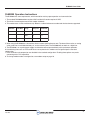
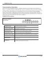
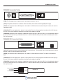
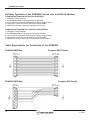
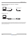
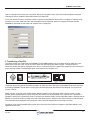
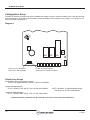
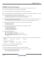
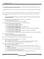
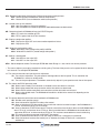
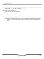
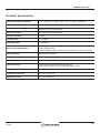
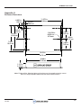
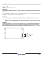
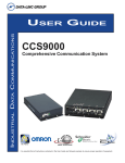
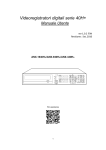
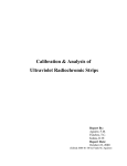
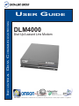
INDUSTRIAL DATA COMMUNICATIONS
USER GUIDE
DLM4000
Dial-Up/Leased Line Modem
It is essential that all instructions contained in the User Guide are followed precisely to ensure proper operation of equipment.
Product User Guide
PN 161-09997-003A
Feb 2005
DLM4000 User Guide
Table of Contents
Page
Operation Instructions
○
○
○
Dia-Up Systems Example
○
○
○
○
○
○
○
○
Lesased Line System Example
LED Descriptions
○
○
Connection Points
○
○
○
○
Verifying Operation
○
○
○
○
○
○
○
○
○
○
○
○
○
○
○
○
○
○
○
○
○
○
○
○
○
○
○
○
○
○
○
○
○
Registers
○
○
○
○
○
○
○
○
○
○
○
○
○
○
Technical Specifications
Troubleshooting
○
○
○
○
○
○
○
○
○
○
○
○
○
○
○
○
○
○
○
○
○
○
○
○
○
○
○
○
○
○
○
○
○
○
○
○
○
○
○
○
○
○
○
○
○
○
○
○
○
○
○
○
○
○
○
○
○
○
○
○
○
○
○
○
○
○
○
○
○
○
○
○
○
○
○
○
○
○
○
○
○
○
○
○
○
○
○
○
○
○
○
○
○
○
○
○
○
○
○
○
○
○
○
○
○
○
○
○
○
○
○
○
○
○
○
○
○
○
○
○
○
○
○
○
○
○
○
○
○
○
○
○
○
○
○
○
○
○
○
○
○
○
○
○
○
○
○
○
○
○
○
○
○
○
○
○
○
○
○
○
○
○
○
○
○
○
○
○
○
○
○
○
○
○
○
○
○
○
○
○
○
○
○
○
○
○
○
○
○
○
○
○
○
○
○
○
○
○
○
○
○
○
○
○
○
○
○
○
○
○
○
○
○
○
○
○
○
○
○
○
○
○
○
○
○
○
○
○
○
○
○
○
○
○
○
○
○
○
○
○
○
○
○
○
○
○
○
○
○
○
○
○
○
○
○
○
○
○
○
○
○
○
○
○
○
○
○
○
○
○
○
○
○
○
○
○
○
○
○
○
○
○
○
○
○
○
○
○
○
○
○
○
○
○
○
○
○
○
○
○
○
○
○
○
○
○
○
○
○
○
○
○
○
○
○
○
○
○
○
○
○
○
○
○
○
○
○
○
○
○
○
○
○
○
○
○
○
○
○
○
○
○
○
○
○
○
○
○
○
○
○
○
○
○
○
○
○
○
○
○
○
○
○
○
○
○
○
○
○
○
○
○
○
○
○
○
○
○
○
○
○
○
○
○
○
○
○
○
○
○
○
Appendix C
Auto Answer Module
PN 161-09997-003A
Feb 2005
○
○
○
○
○
○
○
○
○
○
○
Appendix A
Enclosure Dimensions
○
○
○
○
○
○
○
○
○
○
○
○
○
○
○
○
○
○
○
○
○
○
○
○
○
○
○
○
○
○
○
○
○
○
○
○
○
○
○
○
○
○
○
○
○
○
○
○
○
○
○
○
○
○
○
○
○
○
○
○
○
○
○
○
○
○
○
○
○
○
○
○
○
○
○
○
○
○
○
○
Technical Support
Product Warranty
Return Material Authorization
Contact Information
Appendix B
CCDF Module
○
○
○
○
Setting Up and Using HyperTerminal for Testing
○
○
○
Setting Up Equipment for Bench Test Verification
Command Descriptions
○
○
○
○
○
○
○
○
○
○
○
○
○
○
○
○
○
○
○
○
○
○
○
○
○
○
○
○
○
○
○
○
○
○
○
○
○
○
○
○
○
○
○
○
○
○
○
○
○
○
○
○
○
○
○
○
○
○
○
○
○
○
○
○
○
○
○
○
○
○
○
○
○
○
○
○
○
○
○
○
○
○
○
○
○
○
○
○
○
○
○
○
○
○
○
○
○
○
○
○
○
○
○
○
○
○
○
○
○
○
○
○
○
○
○
○
○
○
○
○
○
○
○
○
○
○
○
○
○
○
○
○
○
○
○
○
○
○
○
○
○
○
○
○
○
○
○
○
○
○
○
○
○
○
○
○
○
○
○
○
○
○
○
○
○
○
○
○
○
○
○
○
○
○
○
○
○
○
○
○
○
○
○
○
○
○
○
○
○
○
○
○
○
○
○
○
○
○
○
○
○
○
○
○
○
○
○
○
○
○
○
○
○
○
○
○
○
○
○
○
○
○
○
○
○
○
○
○
○
○
○
○
○
○
○
○
○
○
○
○
○
○
○
○
○
○
○
○
○
○
○
○
○
○
○
○
○
○
○
○
○
○
○
○
○
○
○
○
○
○
○
○
○
○
○
○
○
○
○
○
○
3
5
5
6
7
8
9
10
13
17
19
20
22
22
22
22
23
24
25
1
DLM4000 User Guide
2
PN 161-09997-003A
Feb 2005
DLM4000 User Guide
DLM4000 Operation Instructions
The DLM4000 has some requirements, which need to be met for proper operation and communication.
1. The standard DLM4000 modem requires 9 VAC and the 24V version requires 24 VDC.
2. The minimal current requirement for this modem is 300 mA.
3. This modem uses a 10-bit word format only. Below is a table of reference to understand the data formats supported.
Start Bit
Data Bits
Parity
Stop Bit
Total Bits
1
8
None
1
10
1
7
None
2
10
1
7
Even, Odd
1
10
4. When using the DLM4000 on a leased line, there are some specifications to note. The leased line must be an analog
voice grade line or unshielded twisted pair, and must be two wire. The DLM4000 will not work on a digital line.
5. The DLM4000 is an asynchronous modem and therefore will not operate directly with synchronous protocols.
6. Handshaking lines such as DTR and RTS are not required for this modem and are ignored per the standard
configuration.
7. Error correction and compression are disabled in the standard configuration. Enabling these options may make
connecting with a PLC impossible.
8. To change modem mode or configuration, see modem setup on page 10.
PN 161-09997-003A
Feb 2005
3
DLM4000 User Guide
Connecting the DLM4000
The DLM4000 provides an RS232 port for the connection to other devices. Below is a diagram of the serial port
configuration. It is important to use the proper cable when connecting equipment to the DLM4000. It is recommended that
only Data-Linc Group cables be used to ensure optimal performance. Commercial serial cables will not always provide
proper configuration. Should you require a cable(s), contact Data-Linc Group at (425) 882-2206 or
email [email protected].
13
1
25
14
Pin Identification for the port
4
Pi n 1
Protective Ground
Pi n 2
DI - Data into the Modem from the PLC
Pi n 3
DO - Data out of the Modem into the PLC
Pi n 4
RTS - Request to send from PLC to Modem, ignored by default
Pi n 5
CTS - Clear to send from Modem to PLC, flow control is disabled
Pi n 6
DSR - Data set ready from Modem to PLC
Pi n 7
GND - Signal Ground
Pi n 8
CD - Carrier Detect
P i n 20
DTR - Data terminal ready form PLC to Modem, ignored by default
PN 161-09997-003A
Feb 2005
DLM4000 User Guide
DLM4000 Communications
The DLM4000 operates with many asynchronous protocols, some of which are listed below. The DLM4000 also provides
different options for connecting PLC’s and other equipment. Examples are provided on the following pages.
Dial-up System Example
Diagram 1
DLM4000 multipoint full duplex system using a PC master and PLC remotes. The system may involve dial-up polling or
periodic retrieval of data from remote locations.
Dial-UP Phone Connection
to Telco Network
RS-232
DATA-LINC
GROUP
(425) 882-2206
DLM4000
C
Master Station
Dial-UP Phone Connection
to Telco Network
DATA-LINC
GROUP
(425) 882-2206
T
RS-232
R
R
PLC
DLM4000
C
T
Dial-UP Phone Connection
to Telco Network
Dial-UP Phone Connection
to Telco Network
PLC
DATA-LINC
GROUP
(425) 882-2206
PLC
DLM4000
C
T
R
RS-232
DLM4000
DATA-LINC
GROUP
(425) 882-2206
C
T
R
RS-232
Leased Line System Example
Diagram 2
Leased or dedicated wire application. Multipoint operation is not an option. Only a point-to-point link is possible in Leased
Line Mode.
PLC
PLC
DATA-LINC
GROUP
(425) 882-2206
DLM4000
C
T
RS-232
R
DATA-LINC
GROUP
(425) 882-2206
DLM4000
C
T
RS-232
R
Leased or Dedicated Line
PN 161-09997-003A
Feb 2005
5
DLM4000 User Guide
Communications Description
Communication with the DLM4000 is possible in a multipoint configuration, but only through dial-up configuration. Per
diagram 1, it is possible to setup a dial-up polling operation. The link is a full-duplex link, which can be set up to 19200 bps.
Leased line mode is another option that can be used when dial-up lines are not available or desired, (see diagram 3). This
link is strictly a point-to-point full-duplex link. On unloaded lines, this link may be up to 20 miles. When the DLM4000
modems are being used on a loaded telephone company leased line the distance is unlimited. No ATDT commands are
required to connect. When the DLM4000 modems are set for leased line operation and powered up, they will connect and
achieve carrier. The communications rate may be set up to 19,200 bps.
DLM4000 LED Descriptions
DATA-LINC GROUP
(425) 882-2206
(MR)
DLM4000
(CD) (SD) (RD)
(TR)
C
6
T
(HS)
(AA)
(OH)
R
(MR) Modem Ready
Lights when the modem is turned on
(TR) Data Terminal Ready
Denoted as DTR. Flashes when DTR signal is detected. The Data-Linc
Group default is to ignore DTR.
(CD) Carrier Detect
Lights when the remote modem's carrier is detected.
(SD) Send Data or TXD
Flashes when the modem is sending data to the remote modem or
when receiving data from the local DTE equipment.
(RD) Receive Data or RXD
Flashes when the modem is receiving data from local DTE equipment.
(HS) High Speed
Lights when line speed is 2400 bps or above. Off when low speed.
(AA) Auto-Answ er
Lights when the modem is set for auto-answer. Flashes when incoming
ring is detected.
(OH) Off-Hook
Lights when the modem is using the telephone line (off-hook). Off whe
the modem is not using the line (on-hook).
PN 161-09997-003A
Feb 2005
DLM4000 User Guide
DLM4000 Connection Points
ON
OFF
9VAC
PHONE
OUT
PHONE
IN
(PWR) The DLM4000 utilizes a toggle switch for powering the modem on and off.
(9VAC) The power connection is made with a barrel connector, which comes on the supplied power supply.
(RS232) The connection for the RS232 port on the modem is a DB25 female connection. Keep in mind that this device is
considered a DCE.
(PHONE OUT) For most applications a phone is not required. Data-Linc Group supplies the modem with an RJ11 plug in
this jack. This may be removed if connection of a phone to the modem is required.
(PHONE IN) Connection of the modem to the telephone company dial-up is done via this RJ11 jack. A dedicated or leased
line may also be used at this jack. Note that this unit is a two wire device and only the two center connection points of the
RJ11 jack are used.
DLM4000 24V Connection Points
PHONE
OUT
PHONE
IN
- +
24VDC
(24 VDC) The power connection to the DLM4000/24V is a terminal block. The connection points are designated in the above
diagram. There is no on or off switch on this version.
(RS232) The connection for the RS232 port on the modem is a DB25 female connection. This device is considered a
DCE.
(PHONE OUT) For most applications a phone is not required. Data-Linc Group supplies the modem with an RJ11 plug in
this jack. This may be removed if connection of a phone to the modem is required.
(PHONE IN) Connection of the modem to the telephone company dial-up is done via this RJ11 jack. A dedicated or leased
line may also be used at this jack. Note that this unit is a two wire device and only the two center connection points of the
RJ11 jack are used.
Not Connected
Connected
Connected
Not Connected
PN 161-09997-003A
Feb 2005
RJ11
Twisted Pair
7
DLM4000 User Guide
Verifying Operation of the DLM4000 Leased Line and Dial-Up Modem
Components Required for Dial-Up Verification
1. A desktop or laptop computer.
2. Two DLM4000 modems configured for dial-up operation.
3. A serial cable for connection to the computer. Refer to diagram below.
4. A paperclip or jumper wire for the serial port of the DLM4000.
5. A phone line simulator or preferably two direct dial-up lines.
Components Required for Leased Line Verification
1. A desktop or laptop computer.
2. Two DLM4000 modems configured for leased line operation.
3. A serial cable for connection to the computer. Refer to diagram below.
4. A paperclip or jumper wire for the serial port of the DLM4000.
5. A phone cord or pair of wires with RJ11 connectors for the modems.
Cable Requirements for Connection of the DLM4000
DLM4000 DB25 Male
DLM4000 DB25 Male
8
Computer DB25 Female
Computer DB9 Female
PN 161-09997-003A
Feb 2005
DLM4000 User Guide
Setting up the Equipment for Bench Test Verification
DLM4000/DL Bench Test
Dial-Up Phone Connection
to Telco Network
RS-232
Master Station
DATA-LINC
GROUP
(425) 882-2206
DLM4000
C
T
Dial-Up Phone Connection
to Telco Network
DATA-LINC
GROUP
(425) 882-2206
DLM4000
C
R
T
R
DLM4000/LL Bench Test
RS-232
Master Station
DATA-LINC
GROUP
(425) 882-2206
DLM4000
C
T
R
DATA-LINC
GROUP
(425) 882-2206
DLM4000
C
T
R
After connecting the equipment in either of the above configurations, HyperTerminal must be launched. If the computer being
used for this test does not have HyperTerminal, another terminal emulation program may be used. The following setup of
HyperTerminal may be referenced if another program is being used. Follow these instructions step by step to achieve the
proper configuration for bench testing.
PN 161-09997-003A
Feb 2005
9
DLM4000 User Guide
Jumper Settings
Note that HyperTerminal is required for connecting the dial-up DLM4000 modems to each other. Leased Line versions only
need to be powered up and they will establish carrier between each other.
The following steps will walk through launching and configuring HyperTerminal to talk to the DLM4000 modem.
1. Launching HyperTerminal
Click on Start at the bottom of the computer desktop and a column of options should be displayed. Next select Programs,
Accessories, Communications and then select HyperTerminal.
Now select the icon labeled “Hypertrm.exe.” Selecting this icon will launch HyperTerminal.
2. Configuring HyperTerminal
After launching HyperTerminal the following setup option will be displayed:
10
PN 161-09997-003A
Feb 2005
DLM4000 User Guide
Type in an appropriate name for your connection. After you have typed a name, select OK. Another window is displayed
requiring the entry of additional information about the configuration.
In this next window, the entry of a phone number is ignored. At the bottom of the window is an option to “Connect using:”
and there is an arrow. Select the arrow and more options will be displayed. Select the computer COM port that the
DLM4000 is connected to. Now select OK. Another menu is displayed:
3. Transferring a Text File
The above settings are standard for the DLM4000. The DLM4000 modems may have been setup for other data rates.
Make sure that the data rates are set the same. Select OK after making the above changes. The HyperTerminal
connection window will now be displayed. At this time, it is necessary to place a paperclip or jumper wire in the serial port
of the receiving modem. The following diagram illustrates how to accomplish this:
ON
13
25
OFF
9VAC
PINS 2 AND 3 JUMPERED
1
14
PHONE
OUT
PHONE
IN
The jumper on the serial port of the receiving modem will allow data that is being sent to the modem to be sent back to the
transmitting DLM4000. The text file that is being sent will be displayed on the screen of the computer. It is now time to
transfer a text file.
Select “transfer” at the top of the window. Some additional options will be displayed. Select “text file transfer.” A new
window appears prompting for a text file to transfer. Any text file may be transferred, but a large file size is preferred. If
Windows is being used, a good file to select is located in the Windows folder. Once the Windows folder is selected, the file
Network.txt can be located by scrolling to the end of the folder directory. Select this file and the text file transfer will begin.
The information being displayed on the computer screen should be readable with no missing characters.
If problems arise, see the troubleshooting section of this manual or contact technical support at (425) 882-2206 or e-mail
[email protected]
PN 161-09997-003A
Feb 2005
11
DLM4000 User Guide
Configuration Setup
To enable AT command configuration of the DLM4000, the modem must be in command mode, which is the default mode
for dial-up operation. To enable command mode, remove the modem cover and place J2 in positions 1-2. Positions 2-3 is
leased-line mode. See diagram 1.
Diagram 3
C84
ZD8
ZD7
R31
U2
U4
U11
U7
U1
J2
Jumper on J2 to be placed
center left for Dial-Up Mode
Jumper on J2 to be placed
center right for Leased-Line Mode
Default Setup Strings
Dial Up Mode (same from master or remote):
AT &F L1 U3=0 &A99 &D0 &R1 \Q0 \N1 %C0 S0=1 &W &W254
Leased Line Mode (Master)
AT &F L1 &D0 &L1 &R1 \Q0 \N1 %C0 %H1 S0=0 &W &W254
NOTE: All Modes: If 1200 & 2400 Baud used
then enter line “AT U3=10 &W &W254”
Leased Line Mode (Remote)
AT &F L1 &D0 &L1 &R1 \Q0 \N1 %C0 %H1 S0=1 &W &W254
***Spaces betweens commands can be ommited, used only to show command separation ***
12
PN 161-09997-003A
Feb 2005
DLM4000 User Guide
DLM4000 Command Descriptions
AT: The attention command clears the command buffer must precede all command lines except A/ and +++.
A/: This command re-executes the last command in the command buffer.
+++: This is the escape sequence to take the modem from data mode to command mode.
An: If n is not specified, answer incoming ring immediately. If n is specified, auto-answer after n rings where n is 1 to 255
B: The B command defines the communications protocol as follows.
B0: Selects CCITT protocol, which is used in Europe and most countries in the world.
B1: Selects Bell protocol, which is mainly used in the U.S. and Canada.
E: This command is used to enable or disable the echo of command characters and is only effective in command mode.
E0: Disables the echo of command characters.
E1: Enables the modem to echo command characters so they can be viewed and verified on the screen.
H: This command instructs the modem to go on or off hook. On hook means hang-up where
H0: Modem goes on-hook.
H1: Modem goes off-hook.
L: This command adjusts the volume of the modem speaker for call progress monitoring.
L0: Selects low speaker volume.
L1: Selects low speaker volume.
L2: Selects medium speaker volume.
L3: Selects high speaker volume.
M: This is the speaker on-off control.
M0: Turns the speaker off at all times.
M1: Turns the speaker on until a connection is established.
M2: Turns the speaker on at all times.
M3: Turns the speaker on until carrier is detected, is turned off when
dialing.
N: Sets the number of times the modems will redial if busy. The redial times counter is cleared to 0 after a connection is
made.
String: N=n
Range: n=0-15
Unit: Time
Default: 0
: Sets the interval between redials.
String: N5=n
Range: 0-255
Unit: 2 seconds
Default: 0
N?: Displays the current settings of the DLM4000s redial times.
N5?: Displays the interval time between redials.
P: Instructs the modem to use pulse dialing to dial a number. ATDT P 882-2206
Q: Enables or disables the sending of response codes after a command line is executed.
Q0: Enable the sending of response codes.
Q1: Disable the sending of response codes.
PN 161-09997-003A
Feb 2005
13
DLM4000 User Guide
S=n: Instructs the modem to dial a stored number previously saved with the &Z command. For example, ATDTS=2. This
would dial a number stored in memory location 2.
Sr?: Displays the contents of a particular S register. For example, ATS8?. This would display the value stored in register
S8.
Sr=n: Changes the value in a particular register. For example, ATS8=1. This could change the value in register S8 to 1.
U3=n: Sets the transmit level in the modem from 0 to a –15dB. To write this register value the string must end with
&W254.
Note: that a setting of zero dB may cause connection problems in some Telco circuits. This value must
match in both modems.
V: This command instructs the DLM4000 to send response codes in a word or digital form.
V0: Sends response codes in digital form.
V1: Sends response codes in word form such as OK or CONNECT.
Xn: This command determines which response codes shall be enabled and disabled.
X0: This command enables the response codes
OK, CONNECT, RING, NO CARRIER and ERROR.
X1: This command enables the response codes
OK, CONNECT, RING, NO CARRIER, ERROR and CONNECT 1200.
X2: This command enables the response codes
OK, CONNECT, RING, NO CARRIER, ERROR, CONNECT 1200, NO DIAL TONE and NO ANSWER.
X3: This command enables the response codes
OK, CONNECT, RING, NO CARRIER, ERROR, CONNECT 1200, BUSY and NO ANSWER.
X4: This command enables the response codes
OK, CONNECT, RING, NO CARRIER, ERROR, CONNECT 1200, NO DIAL TONE, BUSY and NO ANSWER.
Z: This command resets the modem.
Z1: Resets the modem with SCP1(stored configuration profile 1).
Z2: Resets the modem with SCP2(stored configuration profile 2).
&An: Power-on autodial stored phone number n (see &Zn). &A99 disables power-on autodial.
&C: This command determines how the DLM4000 reacts to carrier detect.
&C0: Carrier detect is always forced on.
&C1: The modem tracks the data carrier from the remote one and initializes carrier detect accordingly.
&C2: Carrier detect is forced on during command state, but is tracked on connection.
&D: This command determines how the DLM4000 reacts to DTR.
&D0: Instructs the modem to ignore DTR.
&D1: Instructs the modem to assume command state upon detection of DTR, but maintain an active line
connection.
&D2: Instructs the modem to go on-hook, assume command state, and disable auto-answer upon the detection
of a DTR on-to-off transition.
&D3: Instructs the modem to re-initialize itself when it detects a DTR. The ACP (active configuration profile) will be
overwritten by the SCP(stored configuration profile).
&D4: Instructs the modem to deliver all buffered data before disconnecting to on-off transition.
14
PN 161-09997-003A
Feb 2005
DLM4000 User Guide
&Fn: Restore modem Active Configuration Profile to factory default settings where:
&F0: Restore FDP0 (error detection and data compression)
&F1: Restore FDP1 (no error detection and data compression)
&L: Leased or dial-up line selection.
&L0: Sets the modem for dial-up line operation.
&L1: Sets the modem for leased-line operation dedicated between two destinations.
&R: Determines how the DLM4000 will react to CTS/RTS signals.
&R0: CTS tracks the condition of RTS.
&R1: RTS is ignored and the CTS is forced on.
&V: Displays configuration profiles.
&V0: Displays the ACA, SCP and current modem operational status.
&V1: Displays the STN.
&W: Writes the configuration profile.
&W0: Writes ACP (active configuration profile) to SCP0.
&W1: Writes ACP to the SCP1 (stored configuration profile 1).
&Y: Selects a stored profile.
&Y0: Sets SCP0 as the major SCP.
&Y1: Sets SCP1 as the major SCP.
&Zn=: Stores telephone number. For example AT&Z0=882-2206. Range: n = 0 to 9 which are memory locations
,: The comma allows a pause to be inserted into a dialing string. The time of the pause is set in register S8 which defaults
to 2 seconds. For example ATDT,8822206.
\J: This command controls serial port baud rate adjustment.
\J0: Turns off port adjustment. The port speed is fixed regardless of the line speed. This is used when the
DLM4000 is in normal or reliable mode.
\J1: Turns on the port adjustment. The modem automatically adjusts it’s port speed to match the on-line speed.
\N: This selects the ECDC operation mode.
\N0: Selects normal mode. Error-correction is disabled, but the data buffer is activated.
\N1: Selects direct mode. Both error-correction and the data buffer are deactivated.
\N2: Selects ECDC reliable mode. Both error-correction and the data buffer are activated.
\N3: Selects auto-reliable mode. The DLM4000 will establish a reliable link or normal link depending on the
remote modem.
\Q: This option determines which flow control method the DLM4000 uses.
\Q0: Disables serial port flow control.
\Q1: Uses bi-directional XON/XOFF hardware flow control.
\Q2: Uses uni-directional CTS flow control. Data transmission from the local device stops if the DLM4000 turns
CTS off, and resumes when CTS is turned on.
\Q3: Uses bi-directional CTS/RTS flow control. The data transmission from the local device to the DLM4000 stops
when CTS is off, and resumes when CTS is on. Data transmitted from the DLM4000 to connected device
stops when RTS is off, and resumes when RTS is on. This assumes connected device uses handshaking.
\Q4: The serial port does not respond to XON/XOFF flow control.
\Q5: Uses uni-directional flow control as \Q2, but keeps CTS off until a connection is established.
\Q6: Uses bi-directional hardware flow control just as \Q3 does, but keeps CTS off until a connection is
established.
PN 161-09997-003A
Feb 2005
15
DLM4000 User Guide
\Tn: Inactivity timer. Determines how many minutes the modem hangs up in, if no data is sent or received during a normal
or reliable link. These link types must be used for this option to work.
Range: 0 to 255
Unit: 1 Min.
Default: 0
%Bn: Sets the maximum port baud rate.
n= 300, 1200, 2400, 4800, 7200, 9600, 19200
%C: This command controls data compression.
%C0: Data compression is disabled.
%C1: Enables V.42bis and MNP Class 5 data compression.
%E: This command determines if the DLM4000 will automatically retrain when telephone line quality is poor.
%E0: Disables automatic retrain capability.
%E1: Enables auto-retrain. When the line quality is poor, the DLM4000 makes three attempts to re-establish the
connection, for a total of 6 seconds, before it hangs up. This command is valid at speeds of 2400 bps or
higher.
16
PN 161-09997-003A
Feb 2005
DLM4000 User Guide
DLM4000 Registers
Sn?: This will allow viewing of the register value. Here is an example of how to read register S7.
ATS7?.
Sn=: This will allow modification of the register value. Here is an example of how to change register S7. ATS7=130.
S0: This register determines the number of rings before the modem will answer a call. When S0
is set to 0 the modem will not auto-answer calls.
Range: 0-255 Unit: Ring
S1: This register counts the number of rings on the line when a modem is set to auto-answer.
The register is cleared 8 seconds after the last ring.
S2: This register stores the decimal ASCII value of the escape character. The default value is 43 which is a +.
Range: 0-127 Unit: ASCII
Default: 43
S3: Stores the decimal ASCII value of the carriage return character, which terminates both the command line and the
response code.
Range: 0-127 Unit: ASCII
Default: 13
S4: This register stores the decimal ASCII value of the line feed character, which follows a carriage return after a
response code is sent.
Range: 0-127 Unit: ASCII
Default: 10
S5: This register stores the decimal ASCII value of the backspace character, which is used as the backspace key for
editing and as the character echoed to move the cursor backwards on the screen.
Range: 0-32
Unit: ASCII
Default: 8
S6: Determines how long the modem waits after off-hook before it proceeds to dial. This delay allows the central office
to detect the off-hook status of the line and apply a dial tone. If this is set too short this may not allow a call to go
through. This register is valid only when X0, X1, or X3 is in effect. If X2 or X4 is in effect, the dial tone detection is
enabled and the modem will not blind-dial.
Range: 2-255 Unit: Second Default: 2
S7: Determines how long the modem will wait for a remote carrier signal after it dials or answers.
Range: 1-255 Unit: Second
Default: 30
S8: Determines pause time for a comma.
Range: 0-255 Unit: Second Default: 2
S9: Determines how long a carrier signal must continuously exist before it is recognized as a valid signal by the
DLM4000. A longer time gives DLM4000 time to distinguish the carrier signal from noise.
Range: 1-255 Unit: .1 Sec.
Default: 6
S10: Determines how long the DLM4000 will wait before hanging up after it detects a loss of carrier. This delay permits
the carrier to momentarily disappear without causing the modem to disconnect. If this register is set to 255, the
modem ignores carrier status as though a carrier was always present. S10 should be set to a value larger than S9.
Range: 1-255 Unit .1 Sec.
Default: 14
PN 161-09997-003A
Feb 2005
17
DLM4000 User Guide
Configuring the Modem
The modem requires the use of AT commands to enable dialing when power is applied. The following are the required
commands.
&A: Activates a designated location in memory where the phone number to be dialed is stored.
String: &An
Range: n=000 – 009
To activate location one in memory, the convention would be AT&A001&W.
&Z: Stores a phone number to the designated active memory location set by &A. Note that both &Z and &A use the same
number.
String: &Zn
Range: n=0 – 9
An example of storing a number would be AT&Z1=4258822206&W
The stored number may be verified by entering AT&V1. Up to 10 numbers may be entered into memory. Only one of these
numbers may be active at a time.
18
PN 161-09997-003A
Feb 2005
DLM4000 User Guide
Technical Specifications
Data Communication Standards
CCITT V.32bis, V.32, V.22bis, V.22, V.23, V.21, Bell 103, Bell 212A
Data Compression & Error Correction
CITT V.42bis, V.42, MNP Class 2-5
Protocol
Asynchronous (10 bit word format)
Connection Speed
Up to 19200bps uncompresseed
Reciever Sensitivity
-43 dBm
Transmit Level
0 to -15 dBm
Command Buffer
40 Characters
Built in Non-Bolatile Memory
2 stored configuration profiles
2 factory default profiles
10 stored telephone numbers with 36 characters each in a total of 100 bytes
RS-232 Interface
DB25 Female connection
Telephone Interface
2 wire RJ-11 connection
Transmission Distance
Up to 20 miles on an unloaded line. Unlimited on a Telco loaded line.
Optional Interface
RS-422 four wire and AE-485 two wire interface
AADB interface to have modem redial when carrier is lost
Pow er Requirements
9VAC at 300mA with 3 watt maximum power consumption
Temperature Tolerance
320to 1310F (00to 550C)
Humidity Tolerance
0-95% non-condensing
PN 161-09997-003A
Feb 2005
19
DLM4000 User Guide
DLM4000 Troubleshooting
When connecting modem to terminal emulation program, modem does not respond:
1. Ensure the modem is connected to the COM port that the terminal emulation program is using.
2. Check that the COM port is free and no other devices are using it such as an internal modem.
3. Make sure the cable connecting the modem to the PC is the correct cable. Refer to the cable requirements section of
the manual.
4. Try re-starting the terminal emulation program.
5. Make sure the proper power supply is being used. The DLM4000 requires a 9 VAC power supply for proper operation.
When sending a text file with the modems, the received text has missing characters.
1. Ensure that the communications program’s baud rate matches that of the DLM4000.
2. Make sure the word length is set to a 10bit word and not an 11-bit word. Refer to DLM4000 requirements section of
manual.
A programmed phone number is stored in the modem, but when carrier is lost the modem does not redial.
1. The DLM4000 modem is capable of dialing a stored phone number when the modem is powered up only and will not
redial upon loss of carrier.
2. If the modem has Auto Answer Dial Back board installed, most likely there is no stored phone number or the
configuration is incorrect. Refer to Auto Answer Dial-Back section of the manual.
I am trying to connect to the DLM4000 modem with my PC modem, but it does not work.
Data-Linc Group does not recommend or support the use of another manufacturer’s modem. It is recommended that a
second DLM4000 be purchased for optimal connection.
The leased-line DLM4000 modems are powered up, but they do not try to connect.
1. The modems are most likely not configured for leased line operation.
2. Refer to the DLM4000 requirements for the proper jumper setting in the modem.
The DLM4000 modems have carrier, but my PLCs are not communicating.
1. Make sure that the PLC is setup to use a 10-bit word and that the baud rate matches that of the modem.
2. Verify that the modem cabling is correct. If Data-Linc Group supplies the cable, verify the cable pinout per the supplied
cable diagram. If a cable diagram was present, contact Data-Linc Group Group.
3. Ensure that the PLCs are setup and the addressing is correct. The DLM4000 modem does not require handshaking
and this should not be enabled in the PLC.
4. If a problem is suspected with the DLM4000, a loopback test should be ran if possible. Refer to the section on Setting
Up And Using HyperTerminal For Testing.
When in leased line mode the DLM4000 modems are constantly trying to establish communications with each
other.
1. Verify that the communications line being used is an analog voice grade line and not a digital line.
2. Confirm that the leased line connection at both DLM4000 locations is connected properly. The two center pins of the
jack are the correct pins.
3. Make sure that the leased line is a two wire leased line and not a four wire. The DLM4000 will not operate on a four
wire leased line.
4. Verify proper modem operation with a bench test and a phone patch cord.
5. Is there a possible source of electrical noise near the modem such as a variable frequency drive?
6. If the lines have been provided by the telephone company, check with them to verify line integrity.
7. Are surge suppressors being used? Try removing them and see if the modems connect properly. Some surge devices
may prevent communications.
20
PN 161-09997-003A
Feb 2005
DLM4000 User Guide
When communicating between two PLCs, I have a flashing T LED on the Master and a flashing R LED on the
Remote. I never have a flashing R on the Master and T on the Remote.
1. The poll is getting to the remote PLC, but it is not answering back. Verify that the PLC addressing is correct.
2. If possible, try connecting the PLCs together with a null cable directly. If they do not work, most likely a PLC
programming or processor issue exists.
3. Make sure that no handshaking is used in the PLC.
4. Check and verify that the word length is 10bits and the baud rates match. Verify this on both PLC locations.
5. Make sure the protocol is asynchronous and not synchronous.
6. Verify that the cabling is correct.
After a storm the DLM4000 modem is not longer operating.
1. Verify that surge protection is not damaged.
2. Re-initialize modem configurations.
3. Verify DLM4000 operation with a bench test.
4. Verify that DLM4000 power supplies are still operating properly.
I cannot locate a software driver for the DLM4000 modem.
No driver is necessary for the DLM4000 modem. We configure the modem for the application ahead of time. Industrial
software and logic controllers may offer additional configuration options, but no software driver is required. The DLM4000
modem is not designed or intended for providing Internet access.
I am trying to dial with the DLM4000, but the modem keeps disconnecting before establishing a carrier.
1. Ensure that the equipment connected to the dialing modem is not sending data into the DLM4000’s serial port. Any
data sent into the modem in dial mode is viewed as a command and the dial sequence will be terminated. If it is not
possible to discontinue the transmission of data, contact Data-Linc Group for help.
2. Verify that the modems can connect locally to each other. A possible line problem may exist.
3. Make sure the configuration of both of the DLM4000 modems matches per the configuration sheet.
PN 161-09997-003A
Feb 2005
21
DLM4000 User Guide
Technical Support
Data-Linc Group maintains a fully trained staff of service personnel who are capable of providing complete product
assistance. They can provide you with technical, application and troubleshooting, spare parts and warranty assistance.
Our technical staff is based in Bellevue, Washington USA and may be reached at (425) 882-2206 or e-mail
[email protected]
Product Warranty
Data-Linc Group warrants equipment of its own manufacture to be free from defects in material and workmanship for one
year from date of shipment to original user. Data-Linc Group will replace or repair, at our option, any part found to be
defective. Buyer must return any part claimed defective to Data-Linc Group, transportation prepaid.
Return Material Authorization
If a part needs to be sent to the factory for repair, contact Data-Linc Group’s corporate office and request a Return Material
Authorization (RMA) number. The RMA number identifies the part and the owner and must be included with the part when
shipped to the factory.
Contact Information
Corporate Office
Data-Linc Group
3535 Factoria Blvd. SE
Suite 100
Bellevue, Washington 98006 USA
Telephone: (425) 882-2206
Fax: (425) 867-0865
E-mail: [email protected]
Web site: www.data-linc.com
22
PN 161-09997-003A
Feb 2005
DLM4000 User Guide
Appendix A
Enclosure Dimensions
0.625 in
1.59 cm
0.375 in
0.953 cm
11.275 in
28.64 cm
3.63 in
9.22 cm
6.63 in
16.84 cm
Ø 0.250 in
0.635 cm
6 Places
7.25 in
18.42 cm
3.00 in
7.62 cm
6.00 in
15.24 cm
3.00 in
7.62 cm
10.53 in
26.75 cm
10.00 in
25.40 cm
1.375 in
3.49 cm
Note: Enclosure Size, Mounting Holes and Locations may change without notice, contact
Data-Linc Group (425) 882-2206 for the latest Enclosure Dimensions.
PN 161-09997-003A
Feb 2005
23
DLM4000 User Guide
Appendix B
CCDF Module When Installed
Description
The CCDF module is designed to allow Data-Linc Group dial-up modems to make their connection when continuous RS232
data is flowing into its RS232 port. This device is designed for use with Data-Linc Group dial-up modems DLM4000/DL and
DLM4100/DL.
When a given modem is in dial-up mode it is also in command mode. Any data sent into the RS232 port while the modem is
trying to dial will cause it to disconnect, thus the need for the CCDF.
Installation
Installation of the module is simple. No external power is required for the CCDF module. The module has a male DB25
connector which plugs into the modem. The other end of the module is a female DB25 connector which is connected to the
host device via data cable.
Note: The module is installed between the modem and the host device that is transmitting information constantly.
Operation
Internal circuitry monitors the carrier detect line of the dial-up modem and routes the received RS232 signals depending on
the carrier detect line status. If there is no carrier detect established on the modem the module will pass incoming RS232
data to ground. After the modems have successfully compledted the initiation sequence the carrier detect line of the modem
goes high and RS232 data is allowed to flow into the modem for transmission over the phone line.
CCDF
24
PN 161-09997-003A
Feb 2005
DLM4000 User Guide
Appendix C
AADB (Auto Answer Dial-Back) When Installed
The DLM4000-AA Dial-Up Modem is capable of dialing a stored telephone number when a logic high signal is sent to a
terminal block connection at the rear of the modem. The modem will keep dialing until one of the following occurs:
1. A connection is made.
2. The Logic Flag is cleared(returned to logic low).
3. A second Logic High is presented at the override terminal.
The Auto-Alarm dial out function will not interrupt a call in progress and will not dial out if data is sent to RS232 port.
To activate the dial-up feature when carrier is lost, a voltage of 12 VDC should be applied between G (ground) and L. A
12 VDC level applied to O will override the activated dial-up feature. The time for re-dial is factory adjusted to 50% of R8’s
value on the AADB daughter board. To change the length of time the unit takes to cycle power, open the case and adjust
R8.
Note: Data-Linc Group recommends leaving R8 set at the 50% position.
Typical Connection Diagram
C O L G
+ -
R8
+12
VDC
The following describes the function of the connection points on the screw terminal block.
G
L
O
C
Logic Signal Ground
Alarm Logic Signal (input)
Alarm Override Signal (input)
Carrier Detect Signal (out)
The common ground point for the system is terminal G. The L terminal is an input connection that accepts a +12 VDC input
to activate the timing circuit. The O terminal will stop the timing process when +12 VDC is applied to the input. The C
represents the detected carrier voltage level. The carrier output will be around –7 VDC when carrier is not present. This will
be +7 VDC when the carrier is established.
PN 161-09997-003A
Feb 2005
25